
Related Manuals for PTN MRG88A


Summary of Contents for PTN MRG88A
- Page 1 RGBHV/Stereo Audio Matrix Switcher 8x8 USER MANUAL MRG88A PTN RGBHV/Stereo Audio Matrix Switcher 8x8 Version: MRG88A2010V1.0 PTN Electronics Limited www.PTN-electronics.com...
- Page 2 Please refer to the dealers for the latest details. This manual is copyright PTN Electronics Limited. All rights reserved. No part of this publication may be copied or reproduced without the prior written consent of PTN Electronics Limited.
-
Page 3: Table Of Contents
RGBHV/Stereo Audio Matrix Switcher 8x8 Table of Contents 1. Introduction ....................... 1 1.1. Introduction of MRG88A ................1 1.3. Package Contents..................1 2. Features ........................1 3. Specification ......................1 4. Operations of the Control panel and the Remote Controller ........3 4.1. -
Page 4: Introduction
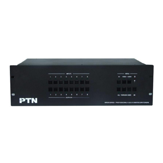
1. Introduction 1.1. Introduction of MRG88A MRG88A is an 8x8 RGBHV matrix switcher following with stereo audio. It supports audio follow and audio breakaway switching. With bandwidth up to 450MHz (-3db), it supports cross-point switching. It shows a good application in broadcast room, television teaching room, commanding center etc. - Page 5 2 = TX, 3 = RX, 5 = Control Port D connector Configurations Front Panel IR Remote Default IR remote Buttons Control Options TCP/IP control by PTNET(PTN's programmable interface) General Power 100VAC ~ 240VAC, Power Supply 50/60Hz Consumption Temperature -20 ~ +70℃...
-
Page 6: Operations Of The Control Panel And The Remote Controller
No.7 to all output channels. Operation: Press buttons in this order “7”, “ALL”. Example2: To transfer all input signals to the corresponding output channels respectively. In another word, to switch to this status: 1->1, 2->2, 3->3, 4->4……8->8. PTN Electronics Limited www.PTN-electronics.com... -
Page 7: Usage Of The Remote Controller
Because the function buttons on the remote controller are the same with the ones on the front control panel, the remote controller shares the same control operation and command format with the control panel. Operations of the remote controller are showed as follows. PTN Electronics Limited www.PTN-electronics.com... -
Page 8: External Connection
The outputs channels, from 0~9, and plusing “10+” for more. F4-2 Panel of the Remote Controller 5. External Connection 5.1. Introduction of the Input and Output Connectors ① ② ③ ④ ⑤ ⑥ F5-1 Rear panel PTN Electronics Limited www.PTN-electronics.com... -
Page 9: Connection With Rs232 Communication Port
BNC connector R(red)、 G (green) 、 B (blue) 、 H (horizontal) 、 V(vertical)carefully. Attention: Please make sure the RGBHV connectors from the source and to the destination should be in the same order, otherwise it world cause color loss or no output signal at all. PTN Electronics Limited www.PTN-electronics.com... -
Page 10: Audio Signal Connection
(Optional), the MVG matrix switcher can be controlled from far-end control systems via the RS232 communication port. This RS232 communication port is a female 9-pin D connector. The definition of its pins is as the table below. PTN Electronics Limited www.PTN-electronics.com... -
Page 11: Connection With Computer
When the switcher connects to the COM1 or COM2 of the computer with control software, users can control it by that computer. To control the switcher, users may use the RS232 software. F 5-3 Connection between MRG matrix switcher and the computer PTN Electronics Limited www.PTN-electronics.com... -
Page 12: System Diagram
RGBHV/Stereo Audio Matrix Switcher 8x8 6. System Diagram F6-1 MRG88A system connection 7. Communication Protocol and Command Codes Communication protocol: RS232 Communication Protocol Baud rate: 9600 Data bit: 8 Stop bit: 1 Parity bit: none Command Command Functions Types Codes /*Type;... - Page 13 1、 Transfer signals from an input channel to all output channels: [x1]All. Example: “3All.” to transfer signals from the input channel No.3 to all output channels. 2、 Transfer all input signals to the corresponding output channels respectively: All#. PTN Electronics Limited www.PTN-electronics.com...
-
Page 14: Safety Operation Guide
In order to guarantee the reliable operation of the equipments and safety of the staff, please abide by the following proceeding in installation, using and maintenance. The system must be earthed properly. Please do not use two blades plugs and ensure PTN Electronics Limited www.PTN-electronics.com... - Page 15 5) As to non-professional or without permission, please DO NOT try to open the casing of the equipment, DO NOT repair it on your own, in case of accident or increasing the damage of the equipment. 6) DO NOT splash any chemistry substance or liquid in the equipment or around. PTN Electronics Limited www.PTN-electronics.com...
-
Page 16: Troubleshooting & Maintenance
8) If the Matrix cannot be controlled by the keys on the front panel, RS232 port or remote controller, the unit may has already been broken. Please send it to the dealer for fixing. PTN Electronics Limited www.PTN-electronics.com... -
Page 17: After-Sales Service
Damage caused by force majeure. Remarks: For any more questions or problems, please try to get help from your local distributor, or email PTN at support@PTN-electronics.com. PTN Electronics Limited www.PTN-electronics.com...
Need help?
Do you have a question about the MRG88A and is the answer not in the manual?
Questions and answers