Table of Contents
Advertisement
Quick Links
Download this manual
See also:
User Manual
Advertisement
Table of Contents

Related Manuals for PTN MTX Series


Summary of Contents for PTN MTX Series
- Page 1 PTN Electronics MTX Series Matrix Switcher User Manual MTX Series ---Combo Matrix Switcher Please read this manual carefully before using this product.
- Page 2 Notice: This MTX series Matrix Switchers User Manual takes example of the Matrix model MTX400. It can be used as user’s manual of other MTX series matrix switcher models. This manual is only an instruction for operators, not for any maintenance usage.
-
Page 3: Safety Operation Guide
MTX Series Matrix Switcher Safety Operation Guide In order to ensure the credibility use of the product and the user’s safety, please comply with the following items during installation and maintenance: The system must be earthed properly. Please do not use two blades plugs and ensure the alternating power supply ranged from 100v to 240v and from 50Hz to 60Hz. -
Page 4: Table Of Contents
1.1 About MTX Matrix Switcher System ..............1 1.2 MTX Series Matrix Switcher Models ..............1 1.2.1 the MTX series chassis (main unit) ..............1 1.2.2 MTX card (changeable cards) ................2 2. PACKING OF THE PRODUCT ..................2 3. - Page 5 MTX Series Matrix Switcher 6.1 Front Panel Description ..................14 6.2 Command Format of the Switching Operation ........... 15 Examples of Operation ..................16 7. COMMUNICATION PROTOCOL AND COMMAND CODES ........16 8. SPECIFICATION ......................19 8.1 Main Unit (Chassis) ....................19 8.2 Changeable Cards ....................
-
Page 6: Introduction
Every card is going with the ID identification. So, it works with the main board by internal protocol. The MTX series product is used for different project, because of the change-able card design. It is the combo solution for multimedia classroom, control rooms, conference rooms, lecture rooms, shopping center etc. -
Page 7: Mtx Card (Changeable Cards)
MTX Series Matrix Switcher 1.2.2 MTX card (changeable cards) According to different situation and users, the MTX card (changeable cards) can be classified into the following models: Specifications Inputs Outputs Signal Format Height Features Models MXDV4 DVI (HDMI) Signal Gang... -
Page 8: Installation
MTX Series Matrix Switcher 3. Installation MTX series matrix switchers adopt metal shell and can be stacked with other device. Moreover, they are rack-mountable enclosure and can be installed in the standard 19 inches case. 4. Front View and Rear View of the Product 4.1 Front View of the MTX200... -
Page 9: Rear View Of The Mtx200
MTX Series Matrix Switcher 4.2 Rear View of the MTX200 4.3 Front View of the MTX400 (Crystal Buttons Version) There are two different button in the front panel. 1: Regular buttons. Black plastic buttons, with red LED indicating. 2: Crystal buttons. -
Page 10: Rear View Of The Mtx400
MTX Series Matrix Switcher 4.4 Rear View of the MTX400 ( Maximum installed 6 cards. The cards in the pictures is only for reference. The user can change it , plug and play. ) 4.5 Front View of the MTX500 (Crystal Buttons Version) There are two different button in the front panel. -
Page 11: Rear View Of The Mtx500
MTX Series Matrix Switcher 4.6 Rear View of the MTX500 ( Maximum installed 8 cards. The cards in the pictures is only for reference. The user can change it , plug and play. ) Please contact us for more information: info@PTN-electronics.com... -
Page 12: Mxdv8
MTX Seri es Matrix S Switcher Function Function T.M.D.S S.Data2- T.M.D.S. Data3+ T.M.D.S S.Data2+ +5V Pow T.M.D.S S. Data 2/4 S Shield Ground ( for +5V) T.M.D.S S. Data 4- Hot Plug Detect T.M.D.S. Data 0- T.M.D.S S. Data 4+ DDC Cl lock T.M.D.S. -
Page 13: Mxvg4
MTX Seri es Matrix S Switcher Pin Nu umber Sig gnal Name n Number Signal Nam MDS Data 2+ SHELL MDS Data 2 Shield 19 Hot Plug De etect MDS Data 2- +5V Power MDS Data 1+ Ground MDS Data 1 Shield 16 DDC Data MDS Data 1-... -
Page 14: Mxvg8
MTX Series Matrix Switcher 5.1.5 MXVG8 VGA cross point matrix switcher 8x8. (Please check the specification from 9.2.2) The bandwidth is up to 350MHz(-3dB) Supporting RGBHV, RGsB, RGBS, RsGsBs, YUV, YC and Composite video. Please check the 5.1.4 for the introduction of VGA pin layout. -
Page 15: Mxus8
MTX Series Matrix Switcher Balanced Audio Connection: Unbalanced Audio Connection: 5.1.9 MXUS8 USB2.0 matrix switcher. 8x8. (Please check the specification from 9.2.4) It does not supports the cross point switching, ONLY one to one switching.. It is working compatible with USB1.0, USB1.1 and PS2. -
Page 16: Mxtp8
MTX Series Matrix Switcher Balanced Audio Connection: Unbalanced Audio Connection: 5.1.11 MXTP8 Twisted pair cross point matrix switcher. 8x8. (Please check the specification from 9.2.6) 8 inputs (4 VGA/Stereo audio and 4RJ45), 8 outputs (8 RJ45), 1 local monitor for VGA and stereo audio. -
Page 17: Id Matching, Between The Slot And Card
MTX Seri es Matrix S Switcher There are 6 6 slots to th e MTX400. Their ID is ranging fro om 1 to 6, fr rom top to b bottom) So, it t means the ID of MTX2 200 is rangin ng from “1”... -
Page 18: Connection Of Rs-232 Communication Port
MTX Series Matrix Switcher 5.3 Connection of RS-232 Communication Port Except the front control panel, the MTX matrix switcher can be control by far-end control system or through the Ethernet control via the RS-232 communication port. This RS-232 communication port is a female 9-pin D connector. The definition of its pins is as the table below. -
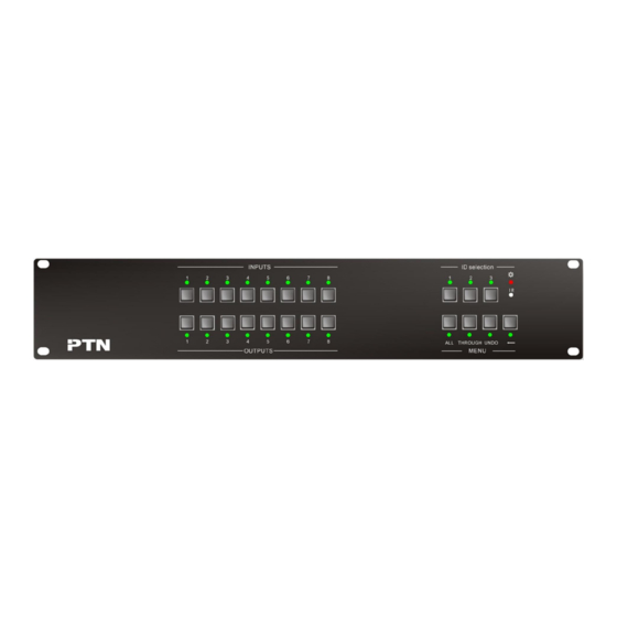
Page 19: System Diagram
MTX Series Matrix Switcher 5.5 System Diagram 6. Operation of the Control Panel 6.1 Front Panel Description PTN Electronics Limited www.PTN-electronics.com... -
Page 20: Command Format Of The Switching Operation
MTX Series Matrix Switcher Buttons Function Description ID selection buttons. It is the ID number of every slot. The user need to select the ID, before controlling this slot(card). Selection Example: you want to control the second slot (card), you need to select the ID button "2"... -
Page 21: Examples Of Operation
MTX Series Matrix Switcher “Output Channel”: press the number of output channels to be controlled 6.3 Examples of Operation Example 1:To transfer the signal of ID”1” from input channel No.1 to output channel No.3,4 Video Audio 1, Press the “1” from the ID selection menu. - Page 22 MTX Series Matrix Switcher /:MessageOn; Switch on the feedback command from the com port. (refer to Detail example 6) Switch to the “demo” mode, 1->1, 2->2, 3->3 … and so on, every 2 seconds, and cycled Demo. switching. Save[Z]. Save the present operation to the preset command [Z]. [Z] ranges from 0 to 9. (refer to Detail example 12) Recall[Z].
- Page 23 MTX Series Matrix Switcher 2、 Transfer all input signals on [Y] card to the corresponding output channels respectively: &[Y] + All#. Example: If the command “&1+All#” is carried out, the status of the first card will be: 1->1, 2->2, 3->3, 4->4……8->8.
-
Page 24: Specification
MTX Series Matrix Switcher &[Q]+ Audioinit. Initialize the Volume/Bass/Treble &[Q]+ VOICE. Checking the level of Volume/Bass/Treble of all the channels [xx] is from preset the volume of input [Y], 61 degrees "00" to "60" &[Q]+ [Y]API[x] [xx] = [UP] Turning up the volume of input [Y] [x]. -
Page 25: Changeable Cards
MTX Series Matrix Switcher 8.2 Changeable Cards 8.2.1 MXDV4, MXDV8, MXHD4 Input Output Input 4 DVI; 8 DVI ; 4 HDMI Output 4 DVI; 8 DVI ; 4 HDMI Input Connector Female DB24+5/HDMI Output Connector Female DB24+5/HDMI Input Level T.M.D.S. 2.9V/3.3V output Level T.M.D.S. -
Page 26: Mxcv8,Mxsv8
MTX Series Matrix Switcher 8.2.3 MXCV8, MXSV8 Input Output Input 8 video Output 8 video Input Connector Female RCA/S-V Output Connector Female RCA/ S-V Input Coupling AC coupling only Switching Type Vertical interval Input Level 0.5 ~ 2.0Vp-p output Level 0.5 ~ 2.0Vp-p... -
Page 27: Mxus8
MTX Series Matrix Switcher Stereo Channel 1% @ 1 kHz, 0.3% @ 20 >80dB@1KHz THD + Noise Separation kHz at nominal level Audio Bits per 18 bits per channel, 2 channels (L, R) Sample 8.2.6 MXUS8 Input Output Input 8 USB2.0 Output 8 USB2.0... -
Page 28: Troubleshooting & Maintenance
MTX Series Matrix Switcher 9. Troubleshooting & Maintenance When the output image in the destination device connected to the MTX Matrix has ghost, such as the projector output with ghost, please check the projector’s setting or try another high quality connection cord.
Need help?
Do you have a question about the MTX Series and is the answer not in the manual?
Questions and answers