
Related Manuals for PTN MATRIX MVG44A


Summary of Contents for PTN MATRIX MVG44A
- Page 1 PTN Electronics VGA Matrix Switchers System User Manual MVG Series ---Computer Graphics (VGA)/Stereo Audio Matrix Please read this manual carefully before using this product.
- Page 2 Please refer to the dealers for the latest details. This manual is copyright PTN Electronics Limited. All rights reserved. No part of this publication may be copied or reproduced without the prior written consent of PTN Electronics Limited.
-
Page 3: Safety Operation Guide
Please do not attempt to maintain and uncover the switcher for there is a high-voltage component inside and the risk of the electric shock. Do not splash any chemical product or liquid on or near the equipment. PTN Electronics Limited www.PTN-electronics.com... -
Page 4: Table Of Contents
......................10 XAMPLES OF PERATION 8. USAGE OF THE REMOTE CONTROLLER ..................11 9. COMMUNICATION PROTOCOL AND COMMAND CODES ............12 10. TECHNICAL SPECIFICATIONS ...................... 14 11. SYSTEM DIAGRAM ......................... 15 12. TROUBLESHOOTING & MAINTENANCE ..................15 PTN Electronics Limited www.PTN-electronics.com... -
Page 5: Introduction
According to different situation and users, the MVG series can be classified into the following models: Video RS232 Specifications Video Inputs Audio I/O Outputs Interface Models MATRIX MVG44A √ √ MATRIX MVG82 √ × MATRIX MVG82A √ √ MATRIX MVG84 √... -
Page 6: Packing Of The Product
Computer Graphics (VGA)/Stereo Audio Matrix Switcher 2. Packing of the Product MVG Matrix Host RS-232 Communication Cord Power Supply Cord CD with Application 3. Installation MVG matrix switchers adopt metal shell and can be stacked with other device. Moreover, they are rack-mountable enclosure and can be installed in the standard 19”... -
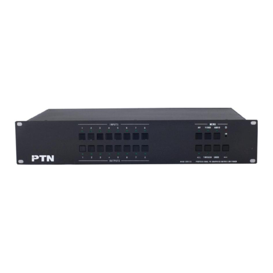
Page 7: Front View Of The Product
Computer Graphics (VGA)/Stereo Audio Matrix Switcher 4. Front View of the Product 4.1 Front View of the MVG44A F 4-1 Front view of the MVG44A 4.2 Front View of the MVG82A、MVG84A、MVG88A F 4-2 Front view of the MVG82A、MVG84A、MVG88A 5. Rear View of the Product 5.1 Rear View of the MVG44A F 5-1 Rear view of the MG44A 5.2 Rear View of the MVG82A、MVG84A、MVG88A... -
Page 8: External Connection
Computer Graphics (VGA)/Stereo Audio Matrix Switcher 6. External Connection 6.1 Introduction of the Input and Output Connectors The MVG matrix switchers adopt female 15-pin HD connectors as the video signal I/O interface, and captive screw connectors as the audio signal I/O interface. Please refer to the rear view figure of the model concerned for details. -
Page 9: How To Connect With The Input And Output Terminals
Computer Graphics (VGA)/Stereo Audio Matrix Switcher F 6-1 Connection between MVG matrix switcher and the computer 6.3 How to Connect with the Input and Output Terminals The MVG matrix switchers may take laptops, desktop computers, graphic workstations and document cameras as their input signal source, and projectors, RP TVs, displayers and amplifiers as their output signal destinations. -
Page 10: How To Connect With The Mvg I/O Devices
Computer Graphics (VGA)/Stereo Audio Matrix Switcher Ring Ring Sleeve Sleeves Sleeves Sleeves Sleeve Ring Ring Unbalanced Input Unbalanced Output Balanced Input Balanced Output F 6-3 Balanced/unbalanced connection on captive screw connector The connection should be selected is up to the interface of the device. When available, the balanced connection is the first choice. -
Page 11: Command Format Of The Switching Operation
Computer Graphics (VGA)/Stereo Audio Matrix Switcher 7.2 Command Format of the Switching Operation With the front control panel, the switcher could be control directly and rapidly by pressing the buttons under below format. “Menu” +“Input Channel” +“Output Channel 1” “Menu”: “AV”, “Audio”, “Video” “Input Channel”: Fill with the number of input channel to be controlled “Output Channel”: Fill with the number of output channels to be controlled 7.3 Examples of Operation... -
Page 12: Usage Of The Remote Controller
Computer Graphics (VGA)/Stereo Audio Matrix Switcher 8. Usage of the Remote Controller With the infrared remote controller, the matrix switcher could be control remotely. Because the function buttons on the remote controller are the same with the ones on the front control panel, the remote controller shares the same control operation and command format with the control panel. -
Page 13: Communication Protocol And Command Codes
Computer Graphics (VGA)/Stereo Audio Matrix Switcher 9. Communication Protocol and Command Codes With this command system, the RS232 software is able to control & operate the MVG Matrix remotely. Communication protocol: Baud rate: 9600 Data bit: 8 Stop bit: 1 Parity bit: none Command Command... - Page 14 Computer Graphics (VGA)/Stereo Audio Matrix Switcher Save[Y]. Save the present operation to the preset command [Y]. [Y] ranges from 0 to 9. Recall[Y]. Recall the preset command [Y]. Clear[Y]. Clear the preset command [Y]. Note: 1. [x1], [x2], [x3] and [x4] are the symbols of input or output channels ranged according to the model of the matrix switcher.
-
Page 15: Technical Specifications
Computer Graphics (VGA)/Stereo Audio Matrix Switcher 11、Switch both video and audio signals synchronously: [x1] B[x2]. Example: To transfer both the video and the audio signals from the input channel No.120 to the output channel No.12,13,15. Run Command: “120B12,13,15.” 12、Inquire the input channel to the output channel [x]: Status[x]. Example: To inquire the input channel to the output channel No.23. -
Page 16: System Diagram
2 = TX, 3 = RX, 5 = GND connector Front Panel IR Remote Default IR remote Buttons Control Options TCP/IP control by PTNET(PTN's programmable interface) General Power Power Supply 100VAC ~ 240VAC, 50/60Hz Consumption Temperature Humidity 10% ~ 90% -20 ~ +70℃... -
Page 17: Troubleshooting & Maintenance
Computer Graphics (VGA)/Stereo Audio Matrix Switcher 12. Troubleshooting & Maintenance When the output image in the destination device connected to the MVG Matrix has ghost, such as the projector output with ghost, please check the projector’s setting or try another high quality connection cord.
Need help?
Do you have a question about the MATRIX MVG44A and is the answer not in the manual?
Questions and answers