Table of Contents
Advertisement
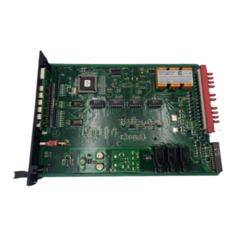
Model TA402A
Zero Two Series Trip Amplifier
Module for Flame Detection
Applications
The information and technical data disclosed in this
document may be used and disseminated only for the
purposes and to the extent specifically authorized in writing
by General Monitors.
Instruction Manual
11/03
General Monitors reserves the right to change published
specifications and designs without prior notice.
Part No
MANTA402A
Revision
E/11-03
Advertisement
Table of Contents

Subscribe to Our Youtube Channel
Related Manuals for General Monitors TA402A

Summary of Contents for General Monitors TA402A
- Page 1 Model TA402A Zero Two Series Trip Amplifier Module for Flame Detection Applications The information and technical data disclosed in this document may be used and disseminated only for the purposes and to the extent specifically authorized in writing by General Monitors.
-
Page 2: Warranty
Model prepaid to General Monitors’ plant or the TA402A. Any attempt to use a representative from which shipment was Field Device that has not been made. In all cases this warranty is limited to... -
Page 3: Table Of Contents
Table of Contents Model TA402A Page Number Warranty ........................i Warnings ........................i Illustrations ......................iii Introduction General Description ................. 1 Features & Benefits ................. 1 Applications ..................2 Specifications System Specifications ..............3 Mechanical Specifications ............... 3 Electrical Specifications ..............3 Environmental Specifications ............ -
Page 4: Illustrations
Engineering & Technical Drawings ..........32 Ordering Information ..............40 Zero Two Series Modules .............. 41 Index ....................Illustrations Figure 1 Isometric View of the Model TA402A ............1 Figure 2 Control Module Coding Strip ..............7 Figure 3 Wire Strip Length..................8 Figure 4 Rear Terminal Designations..............8 Figure 5 Relay Protection Circuit for AC Loads ...........9... -
Page 5: Introduction
(can be Two Series. It is distinguished from the disabled). other modules by its red border and “TA402A" in the upper right corner of the Setup Check Mode: allows the user to view front panel. The Model TA402A is... -
Page 6: Applications
General Monitors Introduction 1.3 Applications The General Monitors Model TA402A is a Trip Amplifier designed for Zero Two Series Flame Detection Applications. Below is a partial list of applications: Refineries Drilling platforms and rigs Gas and oil production platforms Gas collection facilities... -
Page 7: Specifications
Specifications Model TA402A This chapter provides detailed specifications 2.2 Mechanical Specifications for the Model TA402A Zero Two Series Weight: 11.2 oz. (318 grams) Trip Amplifier Module. System, mechanical, electrical and environmental Length: 9.9 inches (251 mm) specifications present the Model TA402A Height: 6.825 inches... -
Page 8: Environmental Specifications
Monitors, Galway, Ireland. Field -40°F to +140°F De vice -40°C to +60°C TA402A Trip Amplifier Module - The trip amplifier module, with a General Monitors’ TA402A 0°F to +150°F flame detector, shall meet the design -18°C to +66°C requirements of CSA and Factory Mutual. - Page 9 Specifications Model TA402A Engineering Specification ( continued The trip amplifier module will generate display codes associated with fault conditions whenever a fault or malfunction occurs. A mode/select switch shall provide the operator front panel access to a setup check mode, a setup mode and an inhibit mode.
- Page 10 General Monitors This page left blank intentionally...
-
Page 11: Installation
3.3 Rear Terminal Connections 4, 8, and 16 channel sizes. Multiple 16 All wire connections to the Model TA402A channel chassis may be connected to each are made to the terminal block located at the other to form larger systems. - Page 12 DPDT relays, 1 open collector output To connect wires to the terminal block on (A2-OC) that follows the logic of the relays the Model TA402A, loosen the desired and 1 open collector output (LA2) that screw, insert the stripped end of the wire and follows the blinking pattern of the front tighten.
-
Page 13: Figure 2 Control Module Coding Strip
Installation Model TA402A Rear Ter mi nal Con nec tions ( Fault Alarm con tin ued The terminal designations for the Fault A1 Im me di ate Warn outputs are: The terminal designations for the A1 Immediate Warn outputs are:... -
Page 14: Figure 3 Wire Strip Length
26d,z Sig nal IN (Ana log) 28d,z VDC Out (+24Vdc) 30d,z DC Com mon Only one Flame De tec tor may be con nected to a Model TA402A. Figure 7 illustrates the inter-connections for the Trip Amplifier & the Flame Detector. -
Page 15: Figure 5 Relay Protection Circuit For Ac Loads
NOTE: When any Open Collector Output is connected to a device not powered by the Figure 10 is a diagram of the Analog Signal same supply powering the TA402A, it will be connections. necessary to remove (cut) Jumper W11 (see figure 33 on page 35). -
Page 16: Detector Location Considerations
General Monitors Installation 3.4 Detector Location Considerations There are no standard rules for detector placement since the optimum location is different for each application. The customer Figure 11 indicates where the power must evaluate conditions at the detector site connections for the chassis are made. in order to make this determination. -
Page 17: Operation
4.1 General Maintenance 4.3 Electrical Outputs Once the Model TA402A has been installed, The electrical outputs on the Model very little maintenance is required other than TA402A consist of relay contacts, open periodic checks to verify the integrity of the collectors and an analog current signal. -
Page 18: Accepting Alarm Conditions
In addition, the Fault Condition associated alarm outputs and the unaccept outputs COPM Fault (FL310X only) (TA402A, UA open collector & FM002A, UA Safe Condition relay) will activate, unless they are already IR Presence (FL3000, FL3100 only) activated. The flashing front panel alarm LED... - Page 19 Operation Model TA402A...
- Page 20 General Monitors Operation...
-
Page 21: User Interfaces
User interfaces are provided so that the Mode allows the user to change these operator may interpret and direct the Model parameters. TA402A in the performance of its various Entering the optional Password is only functions. User interfaces (figure 12) available in the Setup Mode. - Page 22 If the Pass word is En abled: Set the pass word dig its ..Left Right Setup Check Mode Af ter all of the op tions have been se lected, the TA402A will en ter the Setup Check Mode.
-
Page 23: Figure 12 Front Panel Display
User Interfaces Model TA402A Setup Check & Setup Modes ( ENTERING THE PASSWORD con tin ued NOTE: The Password and the A2 Alarm This option applies to the Setup Mode time delay options offer the operator more only: If the password option is enabled, than two choices. - Page 24 Inhibit mode by inhibiting the alarm outputs. After the Model TA402A has entered the Inhibit mode, pressing the Mode/Select switch causes the unit to return to normal operation (see section 5.3).
-
Page 25: Figure 13 Entering The Setup & Setup Check Modes
User Interfaces Model TA402A Setup Check & Setup Modes ( con tin ued The last A2 alarm option to appear on the display will be the alarm time delay. If the A1 alarm is activated continuously for the amount of time specified by this option the A2 alarm outputs will activate. -
Page 26: Figure 15 Entering The Inhibit Mode
Model TA402A will activate the Fault circuit while the unit is in the Inhibit Mode. An nA selection specifies that the Model TA402A will not activate its Fault circuit when the unit is placed in the Inhibit Mode (see section 5.3). An... -
Page 27: Figure 18 A2 Alarm Time Delay Option
STEADY FOR SETUP MODE Fig ure 25 When the Setup Mode is complete, the Fig ure 24 Model TA402A will automatically enter the Setup Check Mode. This allows the operator to view the newly selected options. The unit will return to normal operation after completing the Setup Mode and the Setup Check Mode. -
Page 28: Inhibit Mode Description
Pressing the Mode/Select switch while In is displayed, will cause the unit to enter the Inhibit mode by inhibiting the alarm outputs. After the Model TA402A has entered the Inhibit mode, pressing the Mode/Select switch causes the unit to return to normal operation. -
Page 29: Flame Detectors
6.1 Flame Detectors There are 6 Flame Detectors designed for use with the Model TA402A. Each detector has unique features and advantages: FL3000 UV/IR Flame Detector The FL3000 (figure 26) has a very high... -
Page 31: Figure 26 Fl3000 Picture
Model TA402A Detector Assembly/Accessories FL3100 UV/IR Flame Detector The FL3100 (figure 29) has a very high degree of discrimination when it comes to identifying UV and IR radiation sources. Only the correct combination of each type of radiation will signal a fire. -
Page 32: Uv Phototube
General Monitors Detector Assembly/Accessories 6.2 UV Phototube 6.4 Thermopile The UV phototube is used in the Models The thermopile device is used in the Model FL3000, FL3100, FL3001, FL3101. This FL3002. This device measures the intensity phototube responds to UV radiation within a of IR radiation with a wavelength centered range of 185nm to 260nm (wavelength). -
Page 33: Test Lamps
Model TA402A Detector Assembly/Accessories 6.5 Test Lamps If during operation, the low battery LED TL100 (red) is illuminated, the batteries are nearing The General Monitors TL100 Test Lamp is discharge. However, there is a built in a portable, rechargeable source of ultraviolet battery reserve of approximately 15 minutes. - Page 34 General Monitors Detector Assembly/Accessories Test Lamps - TL102 ( con tin ued The Model TL102 is designed for explosion proof applications for use in Class I, Division 1, Group B, C & D areas. The test lamp operates on internal lead-acid batteries which, when fully charged, will operate continuously for 25 to 30 minutes.
-
Page 35: Glossary Of Terms
Appendix A Model TA402A Glossary of Terms AC - Alternating Current. Flicker Rate - The rate at which the intensity of IR radiation from a fire changes Analog - Continuous, without steps. or modulates. Ambient Temperature - Surrounding or FMRC... - Page 37 General Monitors Appendix A Glossary of Terms ( continued TB - Terminal Block. UV Radiation - Ultraviolet Radiation. Energy with wavelengths shorter than the violet end of the visible spectrum but longer than X-Rays.
-
Page 38: Engineering & Technical Drawings
Appendix B Model TA402A Engineering & Technical Drawings Reference Drawing # 11145-2 Sche matic Di a gram - De tec tor In put Cir cuit Fig ure 33... -
Page 39: Figure 34 & 35 Schematic Diagram - Control Board
General Monitors Appendix B En gi neering & Tech ni cal Draw ings Reference Drawing # 11145-1 Sche matic Di a gram - Con trol Elec tron ics con tin ued Fig ure 34 Left Side... - Page 40 Appendix B Model TA402A En gi neering & Tech ni cal Draw ings Reference Drawing # 11145-1 Sche matic Di a gram - Con trol Elec tron ics Con tinued Fig ure 35 Right Side...
-
Page 41: Figure 36 Schematic Diagram - Display Board
General Monitors Appendix B En gi neering & Tech ni cal Draw ings Reference Drawing # 11150-2 Sche matic Di a gram - Dis play Elec tron ics con tin ued Fig ure 36... -
Page 42: Figure 37 Circuit Card Assembly - Control Board
Appendix B Model TA402A En gi neering & Tech ni cal Draw ings Reference Drawing # 11146-3 Cir cuit Card As sem bly - Con trol Board con tin ued Fig ure 37... -
Page 43: Figure 38 Circuit Card Assembly - Display Board
General Monitors Appendix B En gi neering & Tech ni cal Draw ings Reference Drawing # 11151-2 Cir cuit Card As sem bly - Dis play Board con tin ued Fig ure 38... -
Page 44: Figure 39 Outline & Terminal Connections
Appendix B Model TA402A En gi neering & Tech ni cal Draw ings Reference Drawing # 11281 Outline & Terminal Connections con tin ued 3 CONDUCTOR CABLE- DO NOT SPLICE CABLE UNLESS NECESSARY . ALL SPLICES MUST BE TIGHT AND SOLDERED. -
Page 45: Figure 40 Final Assembly Drawing
General Monitors Appendix B En gi neering & Tech ni cal Draw ings Reference Drawing # 11280-1 Final Assembly con tin ued Fig ure 40... -
Page 46: Ordering Information
Ordering Information The standard configuration for the Model TA402A is: TA402A - 3 2 1 - 1 00 - 0 6 3 TA402A - 32 - 1 00 - 0 • In hibit Mode / Com pati bil ity 3 = Fault Not Ac tive / CAL, FUA (stan dard) -
Page 47: Zero Two Series Modules
Out put De vices Ap pli ca tions Model IN042 Model TA402A Zero Two Se ries Four Zone In put Card Zero Two Se ries Trip Am pli fier Mod ule For Callpoints, Smoke & Ther mal De tec tors... -
Page 48: Index
Index Model TA402A A1 Alarm ..............9 DC ................29 A2 Alarm ..............8 DCS.................29 A2 Alarm Options..........20, 21 Detector AC ................29 Connections ............10 Alarm Type ..............3 A1 ...............9 Digital ..............29 A2 ...............8 Division 1 ..............29 Accepting............14 Drain Loop ..............29 Latched .............15 Resetting ............15... - Page 49 PS002..............40 A2, Common ............8 RL002...............40 Contact Rating ..........3, 9, 13 TA102A ............40 De-Energized A1 Alarm........9 TA202A ............40 De-Energized A2 Alarm........8 TA402A ............40 Energized A1 Alarm...........9 ZN002A ............40 Energized A2 Alarm...........8 Mounting Strip Fault..............13 SEE ALSO ........Coding Strip Fault Contact ............9 mV ................29...
- Page 50 Model TA402A Terminal Block Designations ............8 Setup Check Mode ..........17 Operation............8 Specifications Terminal Connections, Rear ........8 TA402A Control Module ........4 Terms, Glossary ..........29, 30 Cable Parameters ..........3 Test Electrical Classification........3 Card Test ............1, 11 Electrical Specifications ........3 LED Test ............1 Engineering Specifications.........4...
- Page 51 General Monitors C/01-96...
Need help?
Do you have a question about the TA402A and is the answer not in the manual?
Questions and answers