Sign In
Upload
Manuals
Brands
General Monitors Manuals
Amplifier
TA402A
General Monitors TA402A Manuals
Manuals and User Guides for General Monitors TA402A. We have
1
General Monitors TA402A manual available for free PDF download: Instruction Manual
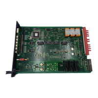
General Monitors TA402A Instruction Manual (51 pages)
Zero Two Series Trip Amplifier Module for Flame Detection Applications
Brand:
General Monitors
| Category:
Amplifier
| Size: 3.07 MB
Table of Contents
Warranty
2
Warnings
2
Table of Contents
3
Illustrations
4
1 Introduction
5
General Description
5
Features & Benefits
5
Applications
6
2 Specifications
7
System Specifications
7
Mechanical Specifications
7
Electrical Specifications
7
Figure 1 Isometric View of the Model TA402A
7
Environmental Specifications
8
Engineering Specifications
8
3 Installation
11
Upon Receipt of Equipment
11
Control Module Installation
11
Rear Terminal Connections
11
Figure 2 Control Module Coding Strip
13
Figure 3 Wire Strip Length
14
Figure 4 Rear Terminal Designations
14
Figure 5 Relay Protection Circuit for AC Loads
15
Detector Location Considerations
16
Applying Power
16
Figure 6 Relay Protection Circuit for DC Loads
16
Figure 7 Detector / Controller Connections
16
4 Operation
17
General Maintenance
17
Electrical Inputs
17
Electrical Outputs
17
Figure 8 Typical External Circuits for Open Collectors
17
Figure 9 Card Test Switch Wiring
17
Figure 10 Analog Signal Connections
17
Accepting Alarm Conditions
18
Figure 11 Power Connections - Rear Chassis
18
5 User Interfaces
21
Types of User Interfaces
21
Setup Check & Setup Modes
21
Figure 12 Front Panel Display
23
Figure 13 Entering the Setup & Setup Check Modes
25
Figure 14 Entering the Password
25
Figure 15 Entering the Inhibit Mode
26
Figure 16 A2 Energized/De-Energized Alarm Option
26
Figure 17 A2 Latching/Non-Latching Alarm Option
26
Figure 18 A2 Alarm Time Delay Option
27
Figure 19 A1 Energized/De-Energized Alarm Option
27
Figure 20 A1 Latching/Non-Latching Alarm Option
27
Inhibit Mode Description
28
Figure 21 Fault / Inhibit Option
28
Figure 22 Entering Card Test Options
28
6 Sensor Assembly/Accessories
29
Flame Detectors
29
Figure 23 Alarm Output Option During a Card Test, Ac / Na
29
Figure 24 Password Enabled/Disabled Option
29
Figure 25 Entering a New Password
29
Figure 26 FL3000 Picture
31
Figure 27 FL3001 Picture
31
Figure 28 FL3002 Picture
31
UV Phototube
32
Pyroelectric Device
32
Thermopile
32
Figure 29 FL3100 Picture
32
Figure 30 FL3101 Picture
32
Figure 31 FL3102 Picture
32
Test Lamps
33
Figure 32 Energy Spectrum
33
7 Appendix
35
Glossary of Terms
35
Engineering & Technical Drawings
38
Figure 33 Schematic Diagram - Detector Input Circuit
38
Figure 34 & 35 Schematic Diagram - Control Board
39
Figure 36 Schematic Diagram - Display Board
41
Figure 37 Circuit Card Assembly - Control Board
42
Figure 38 Circuit Card Assembly - Display Board
43
Figure 39 Outline & Terminal Connections
44
Figure 40 Final Assembly Drawing
45
Ordering Information
46
Zero Two Series Modules
47
8 Index
48
Advertisement
Advertisement
Related Products
General Monitors TA102A
General Monitors TS4000H
General Monitors TA502A
General Monitors TL104
General Monitors TS4000
General Monitors Categories
Security Sensors
Accessories
Control Unit
Monitor
Amplifier
More General Monitors Manuals
Login
Sign In
OR
Sign in with Facebook
Sign in with Google
Upload manual
Upload from disk
Upload from URL