Table of Contents
Advertisement
Quick Links
Advertisement
Table of Contents

Subscribe to Our Youtube Channel
Related Manuals for Supero SuperWorkstation 5036T-T


Summary of Contents for Supero SuperWorkstation 5036T-T
- Page 1 UPER ® 5036T-T uper orkstation USER’S MANUAL Revision 1.0a...
- Page 2 The information in this User’s Manual has been carefully reviewed and is believed to be accurate. The vendor assumes no responsibility for any inaccuracies that may be contained in this document, makes no commitment to update or to keep current the information in this manual, or to notify any person or organization of the updates.
-
Page 3: About This Manual
About This Manual This manual is written for professional system integrators and PC technicians. It provides information for the installation and use of the SuperWorkstation 5036T-T. Installation and maintenance shall be performed by experienced technicians only. The SuperWorkstation 5036T-T is a single processor system based on the SC733TQ-465 mid-tower chassis and the Super X8SAX serverboard. - Page 4 uper orkstation 5036T-T User's Manual Chapter 5: Advanced Serverboard Setup Chapter 5 provides detailed information on the X8SAX serverboard, including the locations and functions of connectors, headers and jumpers. Refer to this chapter when adding or removing processors or main memory and when reconfi guring the serverboard.
- Page 5 Preface Notes...
-
Page 6: Table Of Contents
uper orkstation 5036T-T User's Manual Table of Contents Chapter 1 Introduction Overview ......................1-1 Serverboard Features ..................1-2 Processors ...................... 1-2 Memory ......................1-2 Serial ATA ....................... 1-2 PCI Expansion Slots ..................1-2 Onboard Controllers/Ports ................1-2 Other Features ....................1-3 Chassis Features .................... - Page 7 Table of Contents ESD Precautions ..................... 4-3 Operating Precautions ..................4-4 Chapter 5 Advanced Serverboard Setup Handling the Serverboard ................5-1 Precautions ..................... 5-1 Unpacking ....................... 5-2 Serverboard Installation .................. 5-2 Connecting Cables ..................5-3 Connecting Data Cables ................. 5-3 Connecting Power Cables ................
- Page 8 uper orkstation 5036T-T User's Manual CD and Audio FP ..................5-17 Front Panel Audio Control ................ 5-17 High Defi nition Audio (HDA) ..............5-17 IEEE 1394 Connection ................5-18 Universal Serial Bus (USB) ..............5-18 S/PDIF_Out Connector ................5-19 ) ............5-19 Overheat/Fan Fail LED (JOH1 Power Supply I C Connector..............
- Page 9 Table of Contents Installing Components in the 5.25" Drive Bays ..........6-9 SATA-733 Backplane Specifi cations ............. 6-10 Chapter 7 BIOS Introduction ...................... 7-1 Starting BIOS Setup Utility ................7-1 How To Change the Confi guration Data ............7-1 Starting the Setup Utility ................. 7-2 Main Setup ......................
- Page 10 uper orkstation 5036T-T User's Manual Notes...
-
Page 11: Chapter 1 Introduction
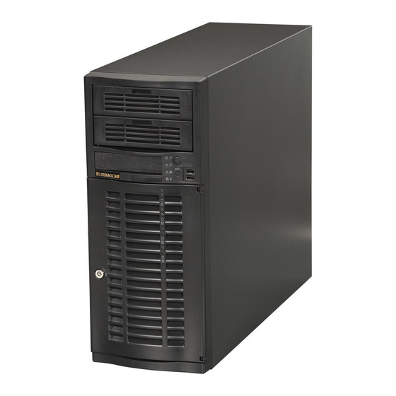
Chapter 1 Introduction Overview The SuperWorkstation 5036T-T is a high-end workstation comprised of two main subsystems: the SC733TQ-465 mid-tower chassis and the X8SAX serverboard. Please refer to our web site for information on operating systems that have been certifi ed for use with the SuperWorkstation 5036T-T (www.supermicro.com). -
Page 12: Serverboard Features
5036T-T User's Manual Serverboard Features At the heart of the SuperWorkstation 5036T-T lies the X8SAX, a single processor serverboard based on the Intel X58 + ICH10R chipset. Below are the main features of the X8SAX. (See Figure 1-1 for a block diagram of the chipset). -
Page 13: Other Features
Front Control Panel The control panel on the SuperWorkstation 5036T-T provides you with system monitoring and control. LEDs indicate power on, network activity, hard disk drive activity and overheat conditions. The control panel also includes a main power button and a system reset button. - Page 14 uper orkstation 5036T-T User's Manual Figure 1-1. Intel X38 Chipset: System Block Diagram Note: This is a general block diagram. Please see Chapter 5 for details. DIMM_CHA Intel Intersil DIMM_CHB VRD 11.1 LGA1366_Processor DIMM_CHC QPI: Up to 6.40 GT/s DDR3:1333/1066/800 PCIE_x16 Intel PCI-E x16 Slot (Gen 2)
-
Page 15: Contacting Supermicro
Chapter 1: Introduction Contacting Supermicro Headquarters Address: Super Micro Computer, Inc. 980 Rock Ave. San Jose, CA 95131 U.S.A. Tel: +1 (408) 503-8000 Fax: +1 (408) 503-8008 Email: marketing@supermicro.com (General Information) support@supermicro.com (Technical Support) Web Site: www.supermicro.com Europe Address: Super Micro Computer B.V. Het Sterrenbeeld 28, 5215 ML 's-Hertogenbosch, The Netherlands Tel:... - Page 16 uper orkstation 5036T-T User's Manual Notes...
-
Page 17: Chapter 2 System Setup
Unpacking the System You should inspect the box the SuperWorkstation 5036T-T was shipped in and note if it was damaged in any way. If the workstation itself shows damage, you should fi le a damage claim with the carrier who delivered it. -
Page 18: Setting Up The System
UPER ORKSTATION 5036T-T User's Manual • To maintain proper cooling, always keep all chassis panels closed and all SATA carriers installed when not being serviced. Setting Up the System You should fi rst open the left side panel (when facing the front of the chassis) to make sure the motherboard is properly installed and all connections have been made. - Page 19 Chapter 2: System Setup Figure 2-1. Accessing the Inside of the 5036T-T...
- Page 20 UPER ORKSTATION 5036T-T User's Manual See the installation and removal sections for the peripheral drives in Chapter Check the Serial ATA disk drives: Depending upon your system's confi gura- tion, your system may have up to four Serial ATA drives already installed. If you need to install or remove an SATA drive, please refer to the appropriate section in Chapter 6.
-
Page 21: Chapter 3 System Interface
Chapter 3: System Interface Chapter 3 System Interface Overview There are several LEDs on the control panel and one on each Serial ATA drive carrier to keep you constantly informed of the overall status of the system as well as the activity and health of specifi c components. There are also two buttons on the chassis control panel. -
Page 22: Control Panel Leds
UPER ORKSTATION 5036T-T User's Manual Control Panel LEDs The control panel located on the front of the SC733TQ-465 chassis has four LEDs. These LEDs provide you with critical information related to different parts of the system. This section explains what each LED indicates when illuminated and any corrective action you may need to take. -
Page 23: Serial Ata Drive Carrier Leds
Chapter 3: System Interface Check the routing of the cables and make sure all fans are present and operating normally. You should also check to make sure that the chassis covers are installed. Finally, verify that the heatsinks are installed properly (see Chapter 5). This LED will remain fl... - Page 24 UPER ORKSTATION 5036T-T User's Manual Notes...
-
Page 25: Chapter 4 System Safety
Chapter 4: System Safety Chapter 4 System Safety Electrical Safety Precautions Note: power should always be disconnected before perform- ing any service on the system. Basic electrical safety precautions shall be followed to protect yourself from harm and the SuperServer 5036T-T from damage: •... -
Page 26: General Safety Precautions
UPER ERVER 5036T-T User's Manual • This product may be connected to an IT power system. In all cases, make sure that the unit is also reliably connected to Earth (ground). • Serverboard Battery: CAUTION - There is a danger of explosion if the onboard battery is installed upside down, which will reverse its polarites (see Figure 4-1). -
Page 27: Esd Precautions
Chapter 4: System Safety • Remove any jewelry or metal objects from your body, which are excellent metal conductors that can create short circuits and harm you if they come into contact with printed circuit boards or areas where power is present. •... -
Page 28: Operating Precautions
UPER ERVER 5036T-T User's Manual Operating Precautions Care must be taken to assure that the chassis cover is in place when the 5036T-T is operating to assure proper cooling. Out of warranty damage to the system can occur if this practice is not strictly followed. Figure 4-1. -
Page 29: Chapter 5 Advanced Serverboard Setup
Chapter 5: Advanced Serverboard Setup Chapter 5 Advanced Serverboard Setup This chapter covers the steps required to install the X8SAX serverboard into the chassis, connect the data and power cables and install add-on cards. All serverboard jumpers and connections are also described. A layout and quick refer- ence chart are included in this chapter for your reference. -
Page 30: Unpacking
uper orkstation 5036T-T User's Manual Unpacking The serverboard is shipped in antistatic packaging to avoid electrical static dis- charge. When unpacking the board, make sure the person handling it is static protected. Serverboard Installation This section explains the fi rst step of physically mounting the X8SAX into the SC733TQ-465 chassis. -
Page 31: Connecting Cables
Chapter 5: Advanced Serverboard Setup Connecting Cables Now that the serverboard is installed, the next step is to connect the cables to the board. These include the data (ribbon) cables for the peripherals and control panel and the power cables. Connecting Data Cables The cables used to transfer data from the peripheral devices have been carefully routed to prevent them from blocking the fl... -
Page 32: I/O Ports
uper orkstation 5036T-T User's Manual Figure 5-1. Control Panel Header Pins Ground x (Key) x (Key) Power On LED HDD LED NIC1 LED NIC2 LED OH/Fan Fail LED Power Fail LED Ground Reset (Button) Ground Power (Button) I/O Ports The I/O ports are color coded in conformance with the PC 99 specifi cation. See Figure 5-2 below for the colors and locations of the various I/O ports. -
Page 33: Processor And Heatsink Installation
Chapter 5: Advanced Serverboard Setup Processor and Heatsink Installation When handling the processor package, avoid placing direct pressure on the label area of the fan. Notes: • Always connect the power cord last and always remove it before adding, re- moving or changing any hardware components. - Page 34 uper orkstation 5036T-T User's Manual After removing the plastic cap, using your thumb and the index fi nger, hold the CPU at the north and south center edges. Align the CPU key (the semi-circle cutout) against the socket key (the notch below the gold color dot on the side of the socket).
- Page 35 Chapter 5: Advanced Serverboard Setup Installation and Removal of the Heatsink Installing the Heatsink Do not apply any thermal grease to the heatsink or the CPU die; the required amount has already been applied. Screw #1 Place the heatsink on top of the CPU so that the four mounting holes are aligned with those on the retention mechanism.
-
Page 36: Installing Memory Modules
uper orkstation 5036T-T User's Manual Installing Memory Modules Note: Check the Supermicro web site for recommended memory modules. CAUTION Exercise extreme care when installing or removing DIMM modules to prevent any possible damage. Press down the release tabs Installing & Removing DIMMs Insert the desired number of DIMMs into the memory slots, starting with DIMM #1A. -
Page 37: Order Of Populating Dimm Slots
Chapter 5: Advanced Serverboard Setup Memory Support The X8SA X supports up to 24 GB of unbuffered ECC/non-ECC DDR3- 1333/1066/800 SDRAM. Notes: • Due to the OS limitations, some operating systems may not show more than 4 GB of memory. •... -
Page 38: Adding Pci Add-On Cards
uper orkstation 5036T-T User's Manual Adding PCI Add-On Cards The 5036T-T can accommodate standard size add-on cards in all slots on the X8SAX serverboard. Installing an Add-on Card Begin by removing the PCI slot shield for the slot you wish to populate. Fully seat the card into the riser card slot, pushing down with your thumbs evenly on both sides of the card. -
Page 39: Serverboard Details
Chapter 5: Advanced Serverboard Setup Serverboard Details Figure 5-4. X8SAX Layout JPUSB1 JPW1 JPW2 KB/Mouse DIMM3A Fan1/ DIMM3B CPU Fan USB 0~3 SMBUS_PS1 DIMM2A DIMM2B S/PDIF DIMM1A LAN1/USB4~5 DIMM1B X8SAX LAN2/USB6~7 JLED Intel HD Audio (7.1) North Bridge LAN CTRL LAN CTRL Fan2 JPW3... -
Page 40: X8Sax Quick Reference
uper orkstation 5036T-T User's Manual X8SAX Quick Reference Jumper Description Default Setting JBT1 CMOS Clear (See Section 5-10) C1/JI SMB to PCI Slots (See Section 5-10) JPAC Audio Enable/Disable Pins 1-2 (Enabled) JPI1 1394a_1/2 Enable/Disable Pins 1-2 (Enabled) JPL1/JPL2 LAN 1/2 Enable/Disable Pins 1-2 (Enabled) JPUSB1 Backplane USB Enable/Disable... -
Page 41: Connector Defi Nitions
Chapter 5: Advanced Serverboard Setup Connector Defi nitions ATX Power 24-pin Connector Pin Defi nitions (JPW1) Pin# Defi nition Pin # Defi nition Main ATX Power Supply +3.3V +3.3V Connector -12V +3.3V The primary power supply connector (JPW1) meets the SSI (Superset ATX) PS_ON 24-pin specifi... -
Page 42: Overheat/Fan Fail Led (Oh)
uper orkstation 5036T-T User's Manual Overheat/Fan Fail LED (OH) OH/Fan Fail LED OH/Fan Fail Indicator Pin Defi nitions (JF1) Status Connect an LED to pins 7 and 8 of Pin# Defi nition State Defi nition JF1 to provide advanced warning of Normal chassis overheating or fan failure. -
Page 43: Fan Headers
Chapter 5: Advanced Serverboard Setup PS/2 Keyboard and ATX PS/2 Keyboard and PS/2 Mouse Port Pin Mouse Ports Defi nitions Pin# Defi nition The ATX PS/2 keyboard and the PS/2 Data mouse are located on the I/O back- panel. The mouse port is above the Ground keyboard port. -
Page 44: Wake-On-Ring
uper orkstation 5036T-T User's Manual Wake-On-Ring Wake-On-Ring Pin Defi nitions The Wake-On-Ring header is des- (JWOR) ignated JWOR. This function allows Pin# Defi nition your computer to receive and be Ground (Black) "awakened" by an incoming call when Wake-up in the suspend state. See the table on the right for pin defi... -
Page 45: Cd And Audio Fp
Chapter 5: Advanced Serverboard Setup CD and Audio FP A 4-pin CD header (CD-IN) and an Audio Input CD Header auxiliary header (Audio FP) allow you Pin Defi nitions (CD-IN) to use the onboard sound for audio Pin# Defi nition CD playback. -
Page 46: Ieee 1394 Connection
uper orkstation 5036T-T User's Manual 1394_1 Pin Defi nitions Pin# Defi n. Pin# Defi n PTPA0+ PTPA0- PTPB0+ PTPB0- IEEE 1394 Connection PWR 1394 PWR 1394 Connectors 1394_1 and 1394_2 provide connectivity for IEEE 1394 1394_2 Pin Defi nitions (Firewire) devices. See the tables on Pin# Defi... -
Page 47: S/Pdif_Out Connector
Chapter 5: Advanced Serverboard Setup S/PDIF_Out Connector An S/PDIF_Out connector is located next to the Backpanel USB ports on the motherboard. The S/PDIF(Sony/ Philips Digital Interface Format) con- nector is used for transporting stereo digital audio signals. It is commonly used to connect the output of a DVD player to a home theater receiver that supports Dolby Digital or DTS... -
Page 48: 5-10 Jumper Settings
uper orkstation 5036T-T User's Manual 5-10 Jumper Settings Explanation of Jumpers To modify the operation of the serverboard, jumpers can be used Connector to choose between optional settings. Pins Jumpers create shorts between two pins to change the function of the con- nector. -
Page 49: Lan1/Lan2 Enable/Disable
Chapter 5: Advanced Serverboard Setup LAN1/LAN2 Enable/Disable LAN1/LAN2 Enable/Disable Change the setting of jumper JPL1 or Jumper Settings (JPL1/JPL2) JPL2 to enable or disable the LAN1 and Jumper Setting Defi nition LAN2 Ethernet ports, respectively. See Pins 1-2 Enabled the table on the right for jumper set- Pins 2-3 Disabled tings. -
Page 50: Usb Wake-Up Enable/Disable
uper orkstation 5036T-T User's Manual USB Wake-Up Enable/Disable Use the JPUSB1/2 jumpers to allow the system to be "Woken Up" via USB devices by pressing a key on the USB keyboard or by clicking the USB mouse of your system. These jumpers are used together with the USB Wake-Up function in the BIOS. -
Page 51: 5-11 Onboard Indicators
Chapter 5: Advanced Serverboard Setup 5-11 Onboard Indicators LAN1/2 LEDs LAN1/2 LED The Ethernet ports (located beside (Connection Speed Indicator) the VGA port) have two LEDs. On LED Color Defi nition each port, one LED indicates activity No Connection or 10 MHz while the other LED may be green, Green 100 MHz... -
Page 52: 5-12 Floppy, Ide, And Sata Ports
uper orkstation 5036T-T User's Manual 5-12 Floppy, IDE, and SATA Ports SATA Ports SATA Port Pin Defi nitions Six Serial ATA (SATA) ports (I-SATA (I-SATA0 ~ I-SATA5 0~5) are located on the motherboard Pin # Defi nition to provide serial link connections. Se- Ground rial Link connections provide faster data transmission than those of the... -
Page 53: Chapter 6 Advanced Chassis Setup
Chapter 6: Advanced Chassis Setup Chapter 6 Advanced Chassis Setup This chapter covers the steps required to install components and perform simple maintenance on the SC733TQ-465B chassis. Following the component installation steps in the order given will eliminate most common problems. If some steps are unnecessary, skip ahead to the next step. -
Page 54: Front Control Panel
UPER ORKSTATION 5036T-T Manual Front Control Panel The front control panel must be connected to the JF1 connector on the motherboard to provide you with system status and alarm indications. A ribbon cable has bundled these wires together to simplify this connection. Connect the cable from JF1 on the motherboard (making sure the red wire plugs into pin 1) to the appropriate comn- nector on the front control panel PCB (printed circuit board). - Page 55 Chapter 6: Advanced Chassis Setup Figure 6-2. Chassis Front View 5.25" Drive Bays Floppy Drive Bay (optional) Main Power System Reset Front Side USB System LEDs SATA Active LED SATA Drive Confi guration Drive IDs are marked on the Front Bezel Lock front bezel.
- Page 56 UPER ORKSTATION 5036T-T Manual Figure 6-3. Chassis Rear View Power Supply I/O Backplane (see Figure 5-2) PCI Expansion Slots...
-
Page 57: System Fans
Chapter 6: Advanced Chassis Setup System Fans A 9-cm chassis cooling fan housed in a fan duct is located just below the peripheral drive bays to provide cool air intake for the system. A 12-cm exhaust fan in the power supply pulls the cool air through the system and expels the hot air. -
Page 58: Installing A New Fan
UPER ORKSTATION 5036T-T Manual Installing a New Fan Replace the failed fan with an identical one (available from Supermicro). After the new fan has been installed into the fan duct, reassemble the fan duct and perform the removal procedure in reverse to install the entire fan duct assembly back into the chassis. -
Page 59: Drive Bay Installation
Chapter 6: Advanced Chassis Setup Drive Bay Installation A bezel covers the front of the chassis but does not need to be removed to access the drives. If you wish to remove the bezel piece, push on the three tabs on the inside left side lip of the front chassis cover. - Page 60 UPER ORKSTATION 5036T-T Manual Figure 6-5. Removing a SATA Drive Carrier...
-
Page 61: Installing Components In The 5.25" Drive Bays
Chapter 6: Advanced Chassis Setup Installing Components in the 5.25" Drive Bays The 5036T-T has two 5.25" drive bays above the SATA drive bays. Components such as a fl oppy drive, IDE hard drives or CD-ROM drives can be installed in these 5.25"... -
Page 62: Sata-733 Backplane Specifi Cations
UPER ORKSTATION 5036T-T Manual Figure 6-6. Adding a Component Without a Drive Carrier SATA-733 Backplane Specifi cations The SATA backplane supports four SATA drives. The SATA drive's LED connec- tor on the SATA backplane is JP26. There are also two power connectors on the backplane - both should be connected. - Page 63 Chapter 6: Advanced Chassis Setup Figure 6-7: SATA-733 Backplane Note: all backplane jumpers are set to their recommended default settings. For details on the backplane jumpers, please refer to the CSE-SAS-733TQ manual (avaialable on the Supermicro web site). 6-11...
- Page 64 UPER ORKSTATION 5036T-T Manual Power Supply The 5036T-T has a single 465W high-effi ciency power supply that features noise- suppression technology for silent operation. The power supply has the capability to automatically sense and operate with an input voltage of 100 or 240V AC. This power supply also has a PFC (Power Factor Correction) feature built in.
-
Page 65: Chapter 7 Bios
Chapter 7: BIOS Chapter 7 BIOS Introduction This chapter describes the AMI BIOS Setup Utility for the X8SAX/C7X58. The AMI ROM BIOS is stored in a Flash EEPROM and can be easily updated. This chapter describes the basic navigation of the AMI BIOS Setup Utility setup screens. Starting BIOS Setup Utility To enter the AMI BIOS Setup Utility screens, press the <Delete>... -
Page 66: Starting The Setup Utility
uper orkstation 5036T-T User's Manual Starting the Setup Utility Normally, the only visible POST (Power On Self Test) routine is the memory test. As the memory is being tested, press the <Delete> key to enter the main menu of the AMI BIOS Setup Utility. From the main menu, you can access the other setup screens. - Page 67 Chapter 7: BIOS Processor The AMI BIOS will automatically display the status of processor as shown below: Speed Physical Count Logical Count System Memory This displays the size of memory available in the system: Populated Size Available Size...
-
Page 68: Advanced Setup Confi Gurations
uper orkstation 5036T-T User's Manual Advanced Setup Confi gurations Use the arrow keys to select Boot Setup and hit <Enter> to access the submenu items: BOOT Feature Quick Boot If Enabled, this option will skip certain tests during POST to reduce the time needed for system boot. - Page 69 Chapter 7: BIOS Wait For 'F1' If Error This forces the system to wait until the 'F1' key is pressed if an error occurs. The options are Disabled and Enabled. Hit 'Del' Message Display This feature displays "Press DEL to run Setup" during POST. The options are Enabled and Disabled.
- Page 70 uper orkstation 5036T-T User's Manual Clock-Spread Spectrum Select Enable to use the feature of Clock Spectrum, which will allow the BIOS to monitor and attempt to reduce the level of Electromagnetic Interference caused by the components whenever needed. The options are Disabled and Enabled. Hardware Prefetcher (Available when supported by the CPU) If set to Enabled, the hardware prefetcher will prefetch streams of data and instruc- tions from the main memory to the L2 cache in the forward or backward manner to...
- Page 71 Chapter 7: BIOS tion and heat dissipation. Please refer to Intel’s web site for detailed information. The options are Disable: Disable GV3 and Enable: Enable GV3. Intel® TurboMode Tech (Available if Intel® EIST technology is Enabled) This feature allows processor cores to run faster than marked frequency in specifi c conditions.
- Page 72 uper orkstation 5036T-T User's Manual C0 - Active. The CPU is processing instructions. C1 - Auto Halt. The core clock (CPU) is off. This is the most basic idle state. Some CPUs support C1E (C1 Enhanced) for lower power consumption. C2 - Stop Clock.
-
Page 73: Advanced Chipset Control
Chapter 7: BIOS DCA Prefetch Delay A DCA Prefetch is used with TOE components to prefetch data in order to shorten execution cycles and maximize data processing effi ciency. Prefetching too fre- quently can saturate the cache directory and delay necessary cache accesses. This feature reduces or increases the frequency the system prefetches data. - Page 74 uper orkstation 5036T-T User's Manual Lockstep - The motherboard uses two areas of memory to run the same set of operations in parallel. Sparing - A preset threshold of correctable errors is used to trigger fail-over. The spare memory is put online and used as active memory in place of the failed memory.
- Page 75 Chapter 7: BIOS Air Flow This is the air fl ow speed to the DIMM modules. Each step is in mm/sec. The default is [1500]. Press "+" or "-" on your keyboard to change this value. Altitude This feature defi nes how many meters above or below sea level the system is located.
- Page 76 uper orkstation 5036T-T User's Manual Intel I/OAT The Intel I/OAT (I/O Acceleration Technology) signifi cantly reduces CPU overhead by leveraging CPU architectural improvements, freeing resources for more other tasks. Available options are Disabled and Enabled. Active State Power Management Select Enabled to start Active-State Power Management for signal transactions between L0 and L1 Links on the PCI Express Bus.
- Page 77 Chapter 7: BIOS IDE / Floppy Confi guration When this submenu is selected, the AMI BIOS automatically detects the presence of the IDE Devices and displays the following items: Floppy A This feature allows the user to select the type of fl oppy drive connected to the sys- tem.
- Page 78 uper orkstation 5036T-T User's Manual Primary IDE Master/Slave, Secondary IDE Master/Slave, Third IDE Master, and fourth IDE Master These settings allow the user to set the parameters of Primary IDE Master/Slave, Secondary IDE Master/Slave, Third and Fourth IDE Master slots. Hit <Enter> to activate the following submenu screen for detailed options of these items.
- Page 79 Chapter 7: BIOS to use Single Word DMA mode 0. It has a data transfer rate of 2.1 MBs. Select SWDMA1 to allow the BIOS to use Single Word DMA mode 1. It has a data transfer rate of 4.2 MBs. Select SWDMA2 to allow the BIOS to use Single Word DMA mode 2.
- Page 80 uper orkstation 5036T-T User's Manual PCI Latency Timer This feature sets the latency Timer of each PCI device installed on a PCI bus. Select 64 to set the PCI latency to 64 PCI clock cycles. The options are 32, 64, 96, 128, 160, 192, 224 and 248.
- Page 81 Chapter 7: BIOS devices. ASK IR (Amplitude Shifted Keying Infra-Red) is a protocol compatible with Sharp® branded PDAs and other infra-red devices. Floppy Controller Select Enabled to enable the onboard Floppy Controller. The options are Enabled and Disabled. Remote Access Confi guration Remote Access This feature allows the user to enable the function of Remote Access.
- Page 82 Voltage Monitoring Vcore, +3.3Vcc, 12V, V_DIMM, 5V, -12V, 3.3VSB, and Vbatt. Note: In the Windows OS environment, the Supero Doctor III settings take precedence over the BIOS settings. When fi rst installed, Supero Doctor III adopts the temperature threshold settings previously set in the BIOS. Any subsequent changes to these thresholds must be made within Supero Doc- tor, since the SD III settings override the BIOS settings.
- Page 83 Chapter 7: BIOS ACPI Confi guration Use this feature to confi gure ACPI (Advanced Confi guration and Power Interface) power management settings for your system. USB Device Wake-Up This feature is used to awaken from Standby mode by a universal serial bus (USB) device (such as, a USB mouse or USB keyboard).
-
Page 84: Security Settings
uper orkstation 5036T-T User's Manual Clear event log This option clears the Event Log memory of all messages. The options are OK and Cancel. Security Settings The AMI BIOS provides a Supervisor and a User password. If you use both pass- words, the Supervisor password must be set fi... -
Page 85: Boot Confi Guration
Chapter 7: BIOS Change User Password Select this feature and press <Enter> to access the submenu , and then type in a new User Password. Clear User Password (Available only if User Password has been set) Password Check Available options are Setup and Always. Boot Sector Virus Protection When Enabled, the AMI BOIS displays a warning when any program (or virus) is- sues a Disk Format command or attempts to write to the boot sector of the hard... -
Page 86: Exit Options
uper orkstation 5036T-T User's Manual Removable Drives This feature allows the user to specify the boot sequence from available Removable Drives. The settings are 1st boot device, 2nd boot device, and Disabled. • 1st Drive • 2nd boot device - [USB: XXXXXXXXX] Exit Options Select the Exit tab from the AMI BIOS Setup Utility screen to enter the Exit BIOS Setup screen. - Page 87 Chapter 7: BIOS Load Optimal Defaults To set this feature, select Load Optimal Defaults from the Exit menu and press <Enter>. Then, select OK to allow the AMI BIOS to automatically load Optimal De- faults to the BIOS Settings. The Optimal settings are designed for maximum system performance, but may not work best for all computer applications.
- Page 88 uper orkstation 5036T-T User's Manual Notes 7-24...
-
Page 89: Appendix A Post Error Beep Codes
Appendix A: POST Error Beep Codes Appendix A POST Error Beep Codes This section lists POST (Power On Self Test) error beep codes for the Phoenix BIOS. POST error beep codes are divided into two categories: recoverable and terminal. This section lists Beep Codes for recoverable POST errors. Recoverable POST Error Beep Codes When a recoverable type of error occurs during POST, BIOS will display a POST code that describes the problem. - Page 90 uper orkstation 5036T-T User's Manual Notes...
-
Page 91: Appendix B Software Installation Instructions
Appendix B: Software Installation Instructions Appendix B Software Installation Instructions B-1 Installing Drivers After you've installed the Windows Operating System, a screen as shown below will appear. You are ready to install software programs and drivers that have not yet been installed. To install these software programs and drivers, click the icons to the right of these items. - Page 92 The Supero Doctor III program is a Web-base management tool that supports remote management capability. It includes Remote and Local Management tools. The local management is called the SD III Client. The Supero Doctor III program included on the CDROM that came with your motherboard allows you to monitor the environment and operations of your system.
- Page 93 Supero Doctor III Interface Display Screen-II (Remote Control) Note: SD III Software Revision 1.0 can be downloaded from our Web site at: ftp:// ftp.supermicro.com/utility/Supero_Doctor_III/. You can also download SDIII User's Guide at: http://www.supermicro.com/PRODUCT/Manuals/SDIII/UserGuide.pdf. For Linux, we will still recommend that you use Supero Doctor II.
- Page 94 uper orkstation 5036T-T User's Manual Notes...
-
Page 95: Appendix C System Specifi Cations
Appendix C: System Specifi cations Appendix C System Specifi cations Processors One Intel Core™ i7 Xeon® or future Intel Nehalem processor families (next generation Intel Xeon® processor) Note: Please refer to our web site for a complete listing of supported processors. Chipset Intel X38 + ICH9R BIOS... - Page 96 uper orkstation 5036T-T User's Manual Weight Gross (Bare Bone): 43 lbs. (19.5 kg.) System Cooling Six (6) paired sets of 4-cm counter-rotating cooling fans (fan speed controlled by BIOS setting) System Input Requirements AC Input Voltage: 100-240 VAC Rated Input Current: 6A (115V) to 3A (240V) Rated Input Frequency: 50/60 Hz Power Supply Rated Output Power: 465W (Part# PWS-465-PQ)
- Page 97 Appendix C: System Specifi cations Regulatory Compliance Electromagnetic Emissions: FCC Class B, EN 55022 Class B, EN 61000-3-2/-3- 3, CISPR 22 Class B Electromagnetic Immunity: EN 55024/CISPR 24, (EN 61000-4-2, EN 61000-4-3, EN 61000-4-4, EN 61000-4-5, EN 61000-4-6, EN 61000-4-8, EN 61000-4-11) Safety: CSA/EN/IEC/UL 60950-1 Compliant, UL or CSA Listed (USA and Canada), CE Marking (Europe) California Best Management Practices Regulations for Perchlorate Materials:...
- Page 98 uper orkstation 5036T-T User's Manual (continued from front) The products sold by Supermicro are not intended for and will not be used in life support systems, medical equipment, nuclear facilities or systems, aircraft, aircraft devices, aircraft/emergency com- munication devices or other critical systems whose failure to perform be reasonably expected to result in signifi...
Need help?
Do you have a question about the SuperWorkstation 5036T-T and is the answer not in the manual?
Questions and answers