Table of Contents
Advertisement
Quick Links
Advertisement
Table of Contents

Subscribe to Our Youtube Channel
Related Manuals for Supero SuperWorkstation 7047GR-TRF


Summary of Contents for Supero SuperWorkstation 7047GR-TRF
- Page 1 UPER ® uper orkstation 7047GR-TRF USER’S MANUAL Revision 1.0a...
- Page 2 The information in this User’s Manual has been carefully reviewed and is believed to be accurate. The vendor assumes no responsibility for any inaccuracies that may be contained in this document, makes no commitment to update or to keep current the information in this manual, or to notify any person or organization of the updates.
-
Page 3: About This Manual
TRF. Installation and maintenance should be performed by experienced technicians only. The SuperWorkstation 7047GR-TRF is based on the SC747TQ-R1620B 4U/Tower rackmount chassis and the Super X9DRG-QF serverboard. Please refer to our web site for an up-to-date list of supported operating systems, processors and memory. - Page 4 UPER ORKSTATION 7047GR-TRF User's Manual this chapter when adding or removing processors or main memory and when reconfi guring the serverboard. Chapter 6: Advanced Chassis Setup Refer to Chapter 6 for detailed information on the SC747TQ-R1620B 4U/Tower rackmount chassis. You should follow the procedures given in this chapter when installing, removing or reconfi...
- Page 5 Preface Notes...
-
Page 6: Table Of Contents
UPER ORKSTATION 7047GR-TRF User's Manual Table of Contents Chapter 1 Introduction Overview ......................1-1 Serverboard Features ..................1-2 Processors ...................... 1-2 Memory ......................1-2 Serial ATA ....................... 1-2 PCI Expansion Slots ..................1-2 Rear I/O Ports ....................1-2 IPMI ......................... 1-2 Chassis Features .................... - Page 7 Table of Contents Installing the Chassis Cover ................2-9 Installing Feet on the Chassis ..............2-10 Chapter 3 System Interface Overview ......................3-1 Control Panel Buttons ..................3-2 Control Panel LEDs ..................3-2 Drive Carrier LEDs ..................3-4 Chapter 4 Standardized Warning Statements for AC Systems About Standardized Warning Statements ............
- Page 8 UPER ORKSTATION 7047GR-TRF User's Manual Connector Defi nitions ................... 5-15 Jumper Settings .................... 5-22 5-10 Onboard Indicators ..................5-24 5-11 SATA Ports ....................5-25 5-12 Installing Software ..................5-26 Supero Doctor III ................... 5-27 Chapter 6 Advanced Chassis Setup Static-Sensitive Devices .................. 6-2 Precautions .....................
-
Page 9: Chapter 1 Introduction
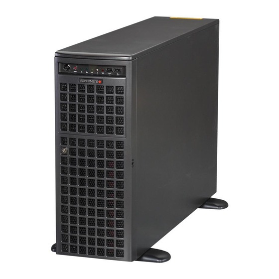
Chapter 1 Introduction Overview The SuperWorkstation 7047GR-TRF is comprised of two main subsystems: the SC747TQ-R1620B 4U/Tower chassis and the X9DRG-QF dual Intel Xeon processor serverboard. Please refer to our web site for information on operating systems that have been certifi ed for use with the system (www.supermicro.com). -
Page 10: Serverboard Features
ORKSTATION 7047GR-TRF User's Manual Serverboard Features At the heart of the SuperWorkstation 7047GR-TRF lies the X9DRG-QF, a dual processor serverboard based on the Intel C602 chipset. Below are the main features of the X9DRG-QF. (See Figure 1-1 for a block diagram of the chipset). -
Page 11: Chassis Features
Chapter 1: Introduction Chassis Features The following is a general outline of the main features of the SC747TQ-R1620B chassis. System Power The SC747TQ-R1620B chassis includes a 1620W high-effi ciency, redundant (1+1) power supply consisting of two power supply modules. In the unlikely event a power supply module fails, replacement is simple and can be done without tools. -
Page 12: System Block Diagram
UPER ORKSTATION 7047GR-TRF User's Manual Figure 1-1. Intel C602 Chipset: System Block Diagram Note: This is a general block diagram. Please see Chapter 5 for details. JPEIC11 PCIE3.0 x8 JPEIC9 PCIE3.0 x8 JPEIC8 PCIE3.0 x16 JPEIC6 PCIE3.0 x16 CPU REAR... -
Page 13: Contacting Supermicro
Chapter 1: Introduction Contacting Supermicro Headquarters Address: Super Micro Computer, Inc. 980 Rock Ave. San Jose, CA 95131 U.S.A. Tel: +1 (408) 503-8000 Fax: +1 (408) 503-8008 Email: marketing@supermicro.com (General Information) support@supermicro.com (Technical Support) Web Site: www.supermicro.com Europe Address: Super Micro Computer B.V. Het Sterrenbeeld 28, 5215 ML 's-Hertogenbosch, The Netherlands Tel:... - Page 14 UPER ORKSTATION 7047GR-TRF User's Manual Notes...
-
Page 15: Chapter 2 Workstation Installation
fi le a damage claim with the carrier who delivered it. Decide on a suitable location for setting up and operating the SuperWorkstation 7047GR-TRF. It should be situated in a clean, dust-free area that is well ventilated. Avoid areas where heat, electrical noise and electromagnetic fi elds are generated. -
Page 16: Warnings And Precautions
UPER ORKSTATION 7047GR-TRF User's Manual • This product is for installation only in a Restricted Access Location (dedicated equipment rooms, service closets and the like). Warnings and Precautions! Rack Precautions • Ensure that the leveling jacks on the bottom of the rack are fully extended to the fl... -
Page 17: Rack Mounting Considerations
Chapter 2: Workstation Installation Rack Mounting Considerations Ambient Operating Temperature If installed in a closed or multi-unit rack assembly, the ambient operating tempera- ture of the rack environment may be greater than the ambient temperature of the room. Therefore, consideration should be given to installing the equipment in an environment compatible with the manufacturer’s maximum rated ambient tempera- ture (Tmra). -
Page 18: Removing The Chassis Cover And Feet
UPER ORKSTATION 7047GR-TRF User's Manual Warning! To prevent bodily injury when mounting or servicing this unit in a rack, you must take special precautions to ensure that the system remains stable. The following guidelines are provided to ensure your safety: •... - Page 19 Chapter 2: Workstation Installation Figure 2-1. Removing the Feet and Chassis Top Cover Chassis Cover Chassis Feet Chassis Cover Lock...
-
Page 20: Installing The Chassis Handles And Inner Rails
UPER ORKSTATION 7047GR-TRF User's Manual Figure 2-2. Identifying the Inner Rails and Chassis Handles Inner Rails Chassis Handle Installing the Chassis Handles and Inner Rails Installing the Inner Rails 1. Locate the chassis handles and handle screws. 2. Align the chassis handle with the front of the chassis and secure with the three chassis handle screws. -
Page 21: Installing The Outer Rails To The Rack
Chapter 2: Workstation Installation Figure 2-3. Installing the Inner Rack Rails Installing the Outer Rails to the Rack Installing the Outer Rails 1. Attach the rear bracket to the middle bracket. 2. Adjust both the brackets to the proper distance so that the rail fi ts snugly into the rack. -
Page 22: Installing The Chassis Into A Rack
UPER ORKSTATION 7047GR-TRF User's Manual Figure 2-5. Installing the Rack Rails Installing the Chassis into a Rack Installing the Chassis 1. Confi rm that chassis includes the inner rails and the outer rails. 2. Align the inner chassis rails with the front of the outer rack rails (C). -
Page 23: Tower Mounting Instructions
Chapter 2: Workstation Installation Tower Mounting Instructions The SC747 chassis is shipped with the chassis cover and feet pre-installed. To use the chassis as a desktop workstation, no other installation is required. Use the instructions in this section if you have converted the chassis for rack use and need to return the chassis to tower mounting. -
Page 24: Installing Feet On The Chassis
UPER ORKSTATION 7047GR-TRF User's Manual Figure 2-7. Placing Chassis Feet Chassis Foot Receptacle Chassis Foot Chassis Screw Installing Feet on the Chassis Installing the Chassis Feet 1. Place the chassis foot in the foot receptacle and slide the foot toward the front of the chassis. -
Page 25: Chapter 3 System Interface
Chapter 3: System Interface Chapter 3 System Interface Overview There are several LEDs on the control panel as well as others on the drive carriers to keep you constantly informed of the overall status of the system as well as the activity and health of specifi... -
Page 26: Control Panel Buttons
UPER ORKSTATION 7047GR-TRF User's Manual Control Panel Buttons There are two push-buttons located on the front of the chassis. These are power on/off button and a reset button. Power The main power switch is used to apply or remove power from the power supply to the workstation. -
Page 27: Power Fail
Chapter 3: System Interface NIC1 Indicates network activity on LAN1 when fl ashing. NIC2 Indicates network activity on LAN2 when fl ashing. Overheat/Fan Fail When this LED fl ashes it indicates a fan failure. When continuously on (not fl ashing) it indicates an overheat condition, which may be caused by cables obstructing the airfl... -
Page 28: Drive Carrier Leds
UPER ORKSTATION 7047GR-TRF User's Manual Drive Carrier LEDs Each SATA drive carrier has two LEDs. • Green: Each drive carrier has a green LED. When illuminated, this green LED (on the front of the drive carrier) indicates drive activity. A connection to the SATA backplane enables this LED to blink on and off when that particular drive is being accessed. -
Page 29: Chapter 4 Standardized Warning Statements For Ac Systems
Chapter 4: Warning Statements for AC Systems Chapter 4 Standardized Warning Statements for AC Systems About Standardized Warning Statements The following statements are industry standard warnings, provided to warn the user of situations which have the potential for bodily injury. Should you have questions or experience difficulty, contact Supermicro's Technical Support department for assistance. - Page 30 UPER ORKSTATION 7047GR-TRF User's Manual Warnung WICHTIGE SICHERHEITSHINWEISE Dieses Warnsymbol bedeutet Gefahr. Sie befi nden sich in einer Situation, die zu Verletzungen führen kann. Machen Sie sich vor der Arbeit mit Geräten mit den Gefahren elektrischer Schaltungen und den üblichen Verfahren zur Vorbeugung vor Unfällen vertraut.
- Page 31 Warning Statements for AC Systems ﺟﺴﺪﻳﺔ ﺍﺻﺎﺑﺔ ﺗﺘﺴﺒﺐ ﻓﻲ ﺣﺎﻟﺔ ﻳﻤﻜﻦ ﺃﻥ ﺍﻧﻚ ﻓﻲ ﺧﻄﺮ ﻳﻌﻨﻲ ﻫﺬﺍ ﺍﻟﺮﻣﺰ !ﺗﺤﺬﻳﺮ ﺍﻟﺪﻭﺍﺋﺮ ﺑﺎﻟﻤﺨﺎﻁﺮ ﺍﻟﻨﺎﺟﻤﺔ ﻋﻦ ﻦ ﻋﻠﻰ ﻋﻠﻢ ، ﻛ ﻣﻌﺪﺍﺕ ﺗﻌﻤﻞ ﻋﻠﻰ ﺃﻱ ﻗﺒﻞ ﺃﻥ ﺍﻟﻜﻬﺮﺑﺎﺋﻴﺔ ﺣﻮﺍﺩﺙ ﺃﻱ ﻭﻗﻮﻉ ﻤﻨﻊ ﻟ ﺍﻟﻮﻗﺎﺋﻴﺔ...
-
Page 32: Installation Instructions
UPER ORKSTATION 7047GR-TRF User's Manual Installation Instructions Warning! Read the installation instructions before connecting the system to the power source. 警告 将此系统连接电源前,请先阅读安装说明。 警告 將系統與電源連接前,請先閱讀安裝說明。 Warnung Vor dem Anschließen des Systems an die Stromquelle die Installationsanweisungen lesen. ¡Advertencia! Lea las instrucciones de instalación antes de conectar el sistema a la red de alimentación. -
Page 33: Circuit Breaker
Chapter 4: Warning Statements for AC Systems Circuit Breaker Warning! This product relies on the building's installation for short-circuit (overcurrent) protection. Ensure that the protective device is rated not greater than: 250 V, 20 A. 警告 此产品的短路(过载电流)保护由建筑物的供电系统提供,确保短路保护设备的额定电 流不大于250V,20A。 警告 此產品的短路(過載電流)保護由建築物的供電系統提供,確保短路保護設備的額定電 流不大於250V,20A。... -
Page 34: Power Disconnection Warning
UPER ORKSTATION 7047GR-TRF User's Manual Waarschuwing Dit product is afhankelijk van de kortsluitbeveiliging (overspanning) van uw electrische installatie. Controleer of het beveiligde aparaat niet groter gedimensioneerd is dan 220V, 20A. Power Disconnection Warning Warning! The system must be disconnected from all sources of power and the power cord removed from the power supply module(s) before accessing the chassis interior to install or remove system components. - Page 35 Chapter 4: Warning Statements for AC Systems ¡Advertencia! El sistema debe ser disconnected de todas las fuentes de energía y del cable eléctrico quitado de los módulos de fuente de alimentación antes de tener acceso el interior del chasis para instalar o para quitar componentes de sistema. Attention Le système doit être débranché...
-
Page 36: Equipment Installation
UPER ORKSTATION 7047GR-TRF User's Manual Equipment Installation Warning! Only trained and qualifi ed personnel should be allowed to install, replace, or service this equipment. 警告 只有经过培训且具有资格的人员才能进行此设备的安装、更换和维修。 警告 只有經過受訓且具資格人員才可安裝、更換與維修此設備。 Warnung Das Installieren, Ersetzen oder Bedienen dieser Ausrüstung sollte nur geschultem, qualifi ziertem Personal gestattet werden. -
Page 37: Restricted Area
Chapter 4: Warning Statements for AC Systems Waarschuwing Deze apparatuur mag alleen worden geïnstalleerd, vervangen of hersteld door geschoold en gekwalifi ceerd personeel. Restricted Area Warning! This unit is intended for installation in restricted access areas. A restricted access area can be accessed only through the use of a special tool, lock and key, or other means of security. -
Page 38: Battery Handling
UPER ORKSTATION 7047GR-TRF User's Manual אזור עם גישה מוגבלת !אזהרה יש להתקין את היחידה באזורים שיש בהם הגבלת גישה. הגישה ניתנת בעזרת .('כלי אבטחה בלבד )מפתח, מנעול וכד ﻣﺤﻈﻮﺭﺓ ﻣﻨﺎﻁﻖ ﻟﺘﺮﻛﻴﺒﻬﺎ ﻓﻲ ﻫﺬﻩ ﺍﻟﻮﺣﺪﺓ ﺗﺨﺼﻴﺺ ﺗﻢ ،ﺃﺩﺍﺓ ﺧﺎﺻﺔ ﻣﻦ ﺧﻼﻝ ﺍﺳﺘﺨﺪﺍﻡ... - Page 39 Chapter 4: Warning Statements for AC Systems Warnung Bei Einsetzen einer falschen Batterie besteht Explosionsgefahr. Ersetzen Sie die Batterie nur durch den gleichen oder vom Hersteller empfohlenen Batterietyp. Entsorgen Sie die benutzten Batterien nach den Anweisungen des Herstellers. Attention Danger d'explosion si la pile n'est pas remplacée correctement. Ne la remplacer que par une pile de type semblable ou équivalent, recommandée par le fabricant.
-
Page 40: Redundant Power Supplies
UPER ORKSTATION 7047GR-TRF User's Manual Redundant Power Supplies Warning! This unit might have more than one power supply connection. All connections must be removed to de-energize the unit. 警告 此部件连接的电源可能不止一个,必须将所有电源断开才能停止给该部件供电。 警告 此裝置連接的電源可能不只一個,必須切斷所有電源才能停止對該裝置的供電。 Warnung Dieses Gerät kann mehr als eine Stromzufuhr haben. Um sicherzustellen, dass der Einheit kein trom zugeführt wird, müssen alle Verbindungen entfernt werden. -
Page 41: Backplane Voltage
Chapter 4: Warning Statements for AC Systems ﺍﻣﺪﺍﺩ ﺍﻟﻄﺎﻗﺔ ﺑﻮﺣﺪﺍﺕ ﻋﺪﺓ ﺍﺗﺼﺎﻻﺕ ﺠﻬﺎﺯ ﺍﻟ ﻳﻜﻮﻥ ﻟﻬﺬﺍ ﻗﺪ ﺍﻟﻜﻬﺮﺑﺎء ﻋﻦ ﻮﺣﺪﺓ ﺍﻟ ﻟﻌﺰﻝ ﻛﺎﻓﺔ ﺍﻻﺗﺼﺎﻻﺕ ﻳﺠﺐ ﺇﺯﺍﻟﺔ Waarschuwing Deze eenheid kan meer dan één stroomtoevoeraansluiting bevatten. Alle aansluitingen dienen verwijderd te worden om het apparaat stroomloos te maken. Backplane Voltage Warning! Hazardous voltage or energy is present on the backplane when the system is... -
Page 42: Comply With Local And National Electrical Codes
UPER ORKSTATION 7047GR-TRF User's Manual מתח בפנל האחורי !הרה אז קיימת סכנת מתח בפנל האחורי בזמן תפעול המערכת. יש להיזהר במהלך .העבודה ﺍﻟﻠﻮﺣﺔ ﺃﻭﺍﻟﻄﺎﻗﺔ ﺍﻟﻤﻮﺟﻮﺩﺓ ﻋﻠﻰ ﺍﻟﺘﻴﺎﺭ ﺍﻟﻜﻬﺮﺑﺎﺋﻲ ﻣﻦ ﺧﻄﺮ ﻫﻨﺎﻙ ﻫﺬﺍ ﺍﻟﺠﻬﺎﺯ ﺧﺪﻣﺔ ﻛﻦ ﺣﺬﺭﺍ ﻋﻨﺪ ﻳﻌﻤﻞ ﺍﻟﻨﻈﺎﻡ ﻋﻨﺪﻣﺎ ﻳﻜﻮﻥ... -
Page 43: Product Disposal
Chapter 4: Warning Statements for AC Systems Attention L'équipement doit être installé conformément aux normes électriques nationales et locales. תיאום חוקי החשמל הארצי !אזהרה הציוד חייבת להיות תואמת לחוקי החשמל המקומיים והארציים התקנת ﺍﻟﻤﺘﻌﻠﻘﺔ ﺍﻟﻤﺤﻠﻴﺔ ﻭﺍﻟﻮﻁﻨﻴﺔ ﻘﻮﺍﻧﻴﻦ ﻳﺠﺐ ﺃﻥ ﻳﻤﺘﺜﻞ ﻟﻠ ﺍﻟﻜﻬﺮﺑﺎﺋﻴﺔ... -
Page 44: Hot Swap Fan Warning
UPER ORKSTATION 7047GR-TRF User's Manual ¡Advertencia! Al deshacerse por completo de este producto debe seguir todas las leyes y reglamentos nacionales. Attention La mise au rebut ou le recyclage de ce produit sont généralement soumis à des lois et/ou directives de respect de l'environnement. Renseignez-vous auprès de l'organisme compétent. - Page 45 Chapter 4: Warning Statements for AC Systems 警告 當您從機架移除風扇裝置,風扇可能仍在轉動。小心不要將手指、螺絲起子和其他 物品太靠近風扇。 Warnung Die Lüfter drehen sich u. U. noch, wenn die Lüfterbaugruppe aus dem Chassis genommen wird. Halten Sie Finger, Schraubendreher und andere Gegenstände von den Öffnungen des Lüftergehäuses entfernt. ¡Advertencia! Los ventiladores podran dar vuelta cuando usted quite ell montaje del ventilador del chasis.
-
Page 46: Power Cable And Ac Adapter
UPER ORKSTATION 7047GR-TRF User's Manual Power Cable and AC Adapter Warning! When installing the product, use the provided or designated connection cables, power cables and AC adaptors. Using any other cables and adaptors could cause a malfunction or a fi re. Electrical Appliance and Material Safety Law prohibits the use of UL or CSA -certifi... - Page 47 Chapter 4: Warning Statements for AC Systems Attention Lors de l'installation du produit, utilisez les bables de connection fournis ou désigné. L'utilisation d'autres cables et adaptateurs peut provoquer un dysfonctionnement ou un incendie. Appareils électroménagers et de loi sur la sécurité Matériel interdit l'utilisation de UL ou CSA câbles certifi...
- Page 48 UPER ORKSTATION 7047GR-TRF User's Manual Notes 4-20...
-
Page 49: Chapter 5 Advanced Serverboard Setup
Chapter 5: Advanced Serverboard Setup Chapter 5 Advanced Serverboard Setup This chapter covers the steps required to install the X9DRG-QF serverboard into the chassis, connect the data and power cables and install add-on cards. All serverboard jumpers and connections are also described. A layout and quick reference chart are included in this chapter for your reference. -
Page 50: Unpacking
UPER ORKSTATION 7047GR-TRF User's Manual Unpacking The serverboard is shipped in antistatic packaging to avoid electrical static discharge. When unpacking the board, make sure the person handling it is static protected. Connecting Cables Several cables need to be connected from the chassis to the serverboard. These include the data cables for the peripherals and control panel and the power cables. -
Page 51: I/O Ports
Chapter 5: Advanced Serverboard Setup Figure 5-1. Control Panel Header Pins Ground FP PWRLED 3.3 V HDD LED ID_UID_SW/3/3V Stby NIC1 Link LED NIC1 Activity LED NIC2 Activity LED NIC2 Link LED Blue+ (OH/Fan Fail/ Red+ (Blue LED Cathode) PWR FaiL/UID LED) Power Fail LED 3.3V Reset... -
Page 52: Installing The Processor And Heatsink
UPER ORKSTATION 7047GR-TRF User's Manual Installing the Processor and Heatsink Warning: When handling the processor package, avoid placing direct pressure on the label area of the fan. Notes: • Always connect the power cord last and always remove it before adding, re- moving or changing any hardware components. - Page 53 Chapter 5: Advanced Serverboard Setup 3. With the lever labeled 'Close 1st' fully retracted, gently push down on the 'Open 1st' lever to open the load plate. Lift the load plate to open it completely. Gently push 4. Using your thumb and the index down to pop the load plate fi...
-
Page 54: Installing The Heatsink
UPER ORKSTATION 7047GR-TRF User's Manual Warning: You can only install the CPU to the socket in one direction. Make sure that the CPU is properly inserted into the socket before closing the load plate. If it doesn't close properly, do not force it as it may damage your CPU. Instead, open the load plate again and double-check that the CPU is aligned properly. -
Page 55: Removing The Heatsink
Chapter 5: Advanced Serverboard Setup Removing the Heatsink 1. Remove the power cord from the system before removing the heatsink. 2. Unscrew the heatsink screws in the sequence as shown in the illustration. 3. Gently wriggle the heatsink to loosen it from the CPU (do not use excessive force!). -
Page 56: Installing Memory
UPER ORKSTATION 7047GR-TRF User's Manual Installing Memory Caution! Exercise extreme care when installing or removing DIMM modules to prevent any possible damage. Installing Memory Modules 1. Insert the desired number of DIMMs into the memory slots, starting with P1-DIMMA1. For best memory performance, please install memory modules of the same type and same speed on the memory slots as indicated on the tables below. - Page 57 Chapter 5: Advanced Serverboard Setup Memory Support for the X9DRG-QF Serverboard The X9DRG-QF serverboard supports up to 512 GB of DDR3-1600/1333/1066/800 RDIMM, LRDIMM or UDIMM ECC/non-ECC memory in 16 DIMM slots. See the following table for memory installation. For the latest memory updates, please refer to our website a at http://www.supermicro.com/products/serverboard.
- Page 58 UPER ORKSTATION 7047GR-TRF User's Manual Populating UDIMM (ECC/Non-ECC) Memory Modules Intel E5-2600 Series Processor UDIMM Memory Support Ranks Per Memory Capacity Speed (MT/s) and Voltage Validated by Slot per Channel DIMM & Per DIMM (SPC) and DIMM Per Channel (DPC)
- Page 59 Chapter 5: Advanced Serverboard Setup Populating LRDIMM ECC Memory Modules Intel E5-2600 Series Processor LRDIMM Memory Support Ranks Per Memory Capacity Speed (MT/s) and Voltage Validated DIMM & Data Per DIMM by Slot per Channel (SPC) and Width DIMM Per Channel (DPC) 1 Slot Per 2 Slots Per (See the Note...
-
Page 60: Adding Pci Add-On Cards
ORKSTATION 7047GR-TRF User's Manual Adding PCI Add-On Cards The 7047GR-TRF can support four PCI-E 3.0 x16 (may suport four double-width GPU cards), two PCI-E 3.0 x8 (1 in x16) and one PCI-E 2.0 x4 (in x8) slots. Installing an Add-on Card 1. -
Page 61: Serverboard Details
Chapter 5: Advanced Serverboard Setup Serverboard Details Figure 5-6. X9DRG-QF Layout (not drawn to scale) LED3 USB2/3 USB0/1 COM1 JUIDB X9DRG-QF CTRL LAN1 LAN2 PS2 KB/MS Rev. 1.02 IPMI_LAN CLOSE 1st CLOSE 1st CPU2 CPU2 OPEN 1st OPEN 1st BIOS CLOSE 1st CLOSE 1st CPU1... - Page 62 UPER ORKSTATION 7047GR-TRF User's Manual Connector Description AUDIO_FP Front Panel Audio Header (Optional) COM1/COM2 Back Panel COM Port1/Front Accessible COM2 Header FAN#1~6, FAN CPU/System Fan Headers (Fan1~Fan4, Fan5: CPU1 Fan, #A~D, FAN11 Fan6: CPU2 Fan, FanA~FanD, Fan11) I-SATA 0-5 Two SATA 3.0 Ports (I-SATA 0-1), four SATA 2.0 Ports (I-...
-
Page 63: Connector Defi Nitions
Chapter 5: Advanced Serverboard Setup Connector Defi nitions Power Connections 24-pin Main Power Connector Pin Defi nitions A 24-pin main power supply connector(JPW1), Pin# Defi nition Pin # Defi nition two 8-pin CPU PWR connectors (JPW2/ +3.3V +3.3V JPW3) and a 4-pin PWR connector (JPW4) -12V +3.3V are provided on the serverboard. - Page 64 UPER ORKSTATION 7047GR-TRF User's Manual NIC1/NIC2 LED Indicators GLAN1/2 LED Pin Defi nitions (JF1) The NIC (Network Interface Controller) Pin# Defi nition LED connection for GLAN port 1 is located on pins 11 and 12 of JF1, and NIC 2 LED the LED connection for GLAN Port 2 is on Pins 9 and 10.
- Page 65 Chapter 5: Advanced Serverboard Setup Power Button The Power Button connection is located on pins 1 and 2 of JF1. Momentarily contacting both pins will power on/off Power Button the system. This button can also be Pin Defi nitions (JF1) confi...
- Page 66 UPER ORKSTATION 7047GR-TRF User's Manual Standby Power Header Standby PWR Pin Defi nitions The +5V Standby Power header is Pin# Defi nition located at JSTBY1 on the motherboard. +5V Standby See the table on the right for pin Ground defi nitions. (You must also have a card...
- Page 67 Chapter 5: Advanced Serverboard Setup Fan Headers There are eleven system/CPU fan Fan Header headers (Fans 1~6, Fans A~D and Fan Pin Defi nitions 11) on the motherboard. All these 4-pin Pin# Defi nition fans headers are backward compatible Ground with traditional 3-pin fans, however, fan +12V speed control is available for 4-pin fans...
- Page 68 UPER ORKSTATION 7047GR-TRF User's Manual TPM/Port 80 Header Pin Defi nitions Pin # Defi nition Pin # Defi nition TPM Header/Port 80 Header LCLK LFRAME# <(KEY)> A Trusted Platform Module/Port 80 LRESET# +5V (X) header is located at JTPM1 to provide...
- Page 69 Chapter 5: Advanced Serverboard Setup IPMB IPMB Header Pin Defi nitions A System Management Bus header Pin# Defi nition for IPMI 2.0 is located at JIPMB1. Data Connect the appropriate cable here Ground to use the IPMB I C connection on Clock your system.
-
Page 70: Jumper Settings
UPER ORKSTATION 7047GR-TRF User's Manual Jumper Settings Explanation of Jumpers To modify the operation of the serverboard, jumpers can be used Connector to choose between optional settings. Pins Jumpers create shorts between two pins to change the function of the connector. - Page 71 Chapter 5: Advanced Serverboard Setup VGA Enable/Disable VGA Enable/Disable Jumper Settings JPG1 allows you to enable or disable Jumper Setting Defi nition the VGA port. The default position is on Pins 1-2 Enabled pins 1 and 2 to enable VGA. See the Pins 2-3 Disabled table on the right for jumper settings.
-
Page 72: 5-10 Onboard Indicators
UPER ORKSTATION 7047GR-TRF User's Manual 5-10 Onboard Indicators Activity LED Link LED GLAN LEDs There are two GLAN ports on the serverboard. An additional IPMI Activity LED Link LED dedicated LAN port is also located above the USB 0/1 ports on the backpanel. -
Page 73: 5-11 Sata Ports
Chapter 5: Advanced Serverboard Setup Rear UID LED The rear UID LED is located at LED3 on the backplane. This LED is used in conjunction with the rear UID switch to provide easy identifi cation of a system that might be in need of service. Refer to UID Switch on Page 2-17 for more information. -
Page 74: 5-12 Installing Software
UPER ORKSTATION 7047GR-TRF User's Manual 5-12 Installing Software After the hardware has been installed, you should fi rst install the operating system and then the drivers. The necessary drivers are all included on the Supermicro CDs that came packaged with your serverboard. -
Page 75: Supero Doctor Iii
Chapter 5: Advanced Serverboard Setup Supero Doctor III The Supero Doctor III program is a Web base management tool that supports remote management capability. It includes Remote and Local Management tools. The local management is called SD III Client. The Supero Doctor III program included on the CD-ROM that came with your serverboard allows you to monitor the environment and operations of your system. - Page 76 UPER ORKSTATION 7047GR-TRF User's Manual Figure 5-9. Supero Doctor III Interface Display Screen (Remote Control) Note: SD III Software Revision 1.0 can be downloaded from our Web Site at: ftp://ftp. supermicro.com/utility/Supero_Doctor_III/. You can also download the SDIII User's Guide at: <http://www.supermicro.com/PRODUCT/Manuals/SDIII/UserGuide.pdf>.
-
Page 77: Chapter 6 Advanced Chassis Setup
Chapter 6: Advanced Chassis Setup Chapter 6 Advanced Chassis Setup This chapter covers the steps required to install components and perform maintenance on the chassis. The only tool you will need to install components and perform maintenance is a Phillips screwdriver. Print this page to use as a reference while setting up your chassis. -
Page 78: Static-Sensitive Devices
UPER ORKSTATION 7047GR-TRF User's Manual Static-Sensitive Devices Electrostatic Discharge (ESD) can damage electronic com ponents. To prevent damage to any printed circuit boards (PCBs), it is important to handle them very carefully. The following measures are generally suffi cient to protect your equipment from... -
Page 79: System Cooling
Chapter 6: Advanced Chassis Setup System Cooling Six heavy-duty fans provide cooling for the chassis. Four fans are located in the mid-section of the chassis with two fans in the rear. These fans circulate air through the chassis as a means of lowering the chassis internal temperature. The fans come pre-installed to the chassis. - Page 80 UPER ORKSTATION 7047GR-TRF User's Manual Figure 6-3. Mid-System Chassis Fans Mid Fan Release Tab Figure 6-4. Rear System Chassis Fans Rear Fan Release...
-
Page 81: Power Supply
Chapter 6: Advanced Chassis Setup Power Supply The SC747 chassis has a 1620W (redundant) power supply. This power supply is auto-switching capable. This enables it to automatically sense and operate at a 100v to 240v input voltage. An amber light will be illuminated on the power supply when the power is off. -
Page 82: Power Supply Connections
UPER ORKSTATION 7047GR-TRF User's Manual Figure 6-5. Power Supply Release Button Release Button Power Supply Connections Connect each of the following cables, as required, by your serverboard manufacturer. In some instances, some cables may not need to be connected. Some cables may not be available with your model. -
Page 83: Confi Guring The Storage Module
Chapter 6: Advanced Chassis Setup Confi guring the Storage Module This section covers confi guring the storage module in the SC747 chassis. Figure 6-6. Chassis in Rack Mount Mode Storage Module Figure 6-7. Chassis in Tower Mode Storage Module Tower or Rack Confi guration The SC747 chassis is shipped in tower mode and can be immediately used as workstation. -
Page 84: Rotating The Storage Module
UPER ORKSTATION 7047GR-TRF User's Manual Rotating the Storage Module Use the procedure below to rotate the storage module for rack confi gurations. Figure 6-8. Removing the Storage Module Storage Module Storage Module Release Lever Rotating the Storage Module for Rack Mounting 1. -
Page 85: Installing Drives In The Storage Module
Chapter 6: Advanced Chassis Setup 5. Turn the storage module 90 degrees (as illustrated). 6. Reinsert the module into the chassis and reconnect the cords. Installing Drives in the Storage Module The storage module (Figure 6-9) includes three full sized drive bays and the front LED panel. -
Page 86: Removing A Drive Carrier
UPER ORKSTATION 7047GR-TRF User's Manual Removing a Drive Carrier Use the procedure below to add hard drives to the drive carriers. Adding Hard Drives to the Drive Carriers 1. Open the chassis cover. 2. Locate the drive tray release tab for the slot you want to place the peripheral drive (see Figure 6-10). - Page 87 Chapter 6: Advanced Chassis Setup 4. Place the hard drive to the hard drive tray. The hard drive may not completely fi ll the tray. See Figure 6-11 for details. 5. Secure the hard drive to the carrier with four screws from the bottom. 6.
-
Page 88: Adding Peripheral Drives
UPER ORKSTATION 7047GR-TRF User's Manual Adding Peripheral Drives You can add up to three peripheral drives (DVD-ROM, CD-ROM, fl oppy drive, etc.) to the drive trays using the procedure below. Adding Peripheral Drives 1. Open the chassis cover. 2. Locate the drive tray release tab for the slot you want to place the peripheral drive. -
Page 89: Installing Hard Drives In The Chassis
Chapter 6: Advanced Chassis Setup Installing Hard Drives in the Chassis Chassis hard drives are mounted in drive carriers to simplify their installation and removal from the chassis. These carriers also help promote proper airfl ow for the drive bays. Installing Hard Drives 1. - Page 90 UPER ORKSTATION 7047GR-TRF User's Manual 5. Place a hard drive in the drive tray (see Figure 6-14). 6. Secure the hard drive to the tray using four screws. Figure 6-14. Removing a Dummy Drive Tray Drive Tray SAS/SATA Hard Drive 7.
-
Page 91: Chapter 7 Bios
Chapter 7: BIOS Chapter 7 BIOS Introduction This chapter describes the AMI BIOS Setup utility for the X9DRG-QF. It also provides the instructions on how to navigate the AMI BIOS Setup utility screens. The AMI ROM BIOS is stored in a Flash EEPROM and can be easily updated. Starting BIOS Setup Utility To enter the AMI BIOS Setup utility screens, press the <Del>... -
Page 92: Main Setup
UPER ORKSTATION 7047GR-TRF User's Manual How To Change the Confi guration Data The confi guration data that determines the system parameters may be changed by entering the AMI BIOS Setup utility. This Setup utility can be accessed by pressing <Delete> at the appropriate time during system boot. - Page 93 Chapter 7: BIOS The AMI BIOS Main menu displays the following information: System Date/System Time Use this option to change the system time and date. Highlight System Time or System Date using the arrow keys. Enter new values through the keyboard and press <Enter>.
-
Page 94: Advanced Setup Confi Gurations
UPER ORKSTATION 7047GR-TRF User's Manual Advanced Setup Confi gurations Select the Advanced tab to access the following submenu items. Boot Features Quiet Boot This feature allows the user to select bootup screen display between POST mes- sages and the OEM logo. Select Disabled to display the POST messages. Select Enabled to display the OEM logo instead of the normal POST messages. - Page 95 Chapter 7: BIOS Interrupt 19 Capture Interrupt 19 is the software interrupt that handles the boot disk function. When this item is set to Enabled, the ROM BIOS of the host adaptors will "capture" Interrupt 19 at bootup and allow the drives that are attached to these host adaptors to function as bootable disks.
- Page 96 UPER ORKSTATION 7047GR-TRF User's Manual • CPU Stepping • Maximum CPU Speed • Minimum CPU Speed • Processor Cores • Intel HT (Hyper-Threading) Technology • Intel VT-x Technology • Intel SMX Technology • L1 Data Cache • L1 Code Cache •...
- Page 97 Chapter 7: BIOS Active Processor Cores Set to Enabled to use a processor's second core and above. (Please refer to Intel's website for more information.) The options are All, 1, 2, 4 and 6. Limit CPUID Maximum This feature allows the user to set the maximum CPU ID value. Enable this function to boot the legacy operating systems that cannot support processors with extended CPUID functions.
- Page 98 UPER ORKSTATION 7047GR-TRF User's Manual Intel® Virtualization Technology (Available when supported by the CPU) Select Enabled to support Intel Virtualization Technology, which will allow one platform to run multiple operating systems and applications in independent parti- tions, creating multiple "virtual" systems in one physical computer. The options are Enabled and Disabled.
- Page 99 Chapter 7: BIOS CPU C6 Report (Available when Power Technology is set to Custom) Select Enabled to allow the BIOS to report the CPU C6 State (ACPI C3) to the operating system. During the CPU C6 State, the power to all cache is turned off.
-
Page 100: North Bridge
UPER ORKSTATION 7047GR-TRF User's Manual Short Duration Power Limit This item displays the time period during which short duration power is main- tained. The default setting is 0. Chipset Confi guration North Bridge This feature allows the user to confi gure the settings for the Intel North Bridge. - Page 101 Chapter 7: BIOS CPU1 Slot 4 PCI-E 3.0 x16 OPROM This feature allows the user to set the PCI-Exp bus speed for the slot specifi ed above. The options are Gen1 (Generation 1), Gen2 and Gen3. IIO 2 PCIe Port Bifurcation Control This submenu confi...
- Page 102 UPER ORKSTATION 7047GR-TRF User's Manual DIMM Confi guration This section displays the following DIMM information. Current Memory Mode This item displays the current memory mode. Current Memory Speed This item displays the current memory speed. Mirroring This item displays if memory mirroring is supported by the motherboard. Memory mirroring creates a duplicate copy of the data stored in the memory to enhance data security.
- Page 103 Chapter 7: BIOS Channel Interleaving This feature selects from the different channel interleaving methods. The options are Auto, 1 Way, 2 Way, 3, Way, and 4 Way. Rank Interleaving This feature allows the user to select a rank memory interleaving method. The options are Auto, 1 Way, 2 Way, 4, Way, and 8 Way.
- Page 104 UPER ORKSTATION 7047GR-TRF User's Manual South Bridge Confi guration This feature allows the user to confi gure the settings for the Intel PCH chip. PCH Information This feature displays the following PCH information. Name: This item displays the name of the PCH chip.
- Page 105 Chapter 7: BIOS SATA Confi guration When this submenu is selected, the AMI BIOS automatically detects the presence of IDE or SATA devices and displays the following items. SATA Port0~SATA Port5: The AMI BIOS displays the status of each SATA port as detected by the BIOS.
- Page 106 UPER ORKSTATION 7047GR-TRF User's Manual RAID Mode The following items are displayed when RAID Mode is selected: Port 0~5 Hot Plug Select Enabled to enable hot-plug support for the particular port. The options are Enabled and Disabled. SCU (Storage Control Unit) Confi guration Storage Controller Unit Select Enabled to enable PCH SCU storage devices.
- Page 107 Chapter 7: BIOS SERR# Generation Select Enabled to allow a PCI device to generate an SERR number for a PCI Bus Signal Error Event. The options are Enabled and Disabled. Maximum Payload Select Auto to allow the system BIOS to automatically set the maximum payload value for a PCI-E device to enhance system performance.
- Page 108 UPER ORKSTATION 7047GR-TRF User's Manual Network Stack Select Enabled enable PXE (Preboot Execution Environment) or UEFI (Unifi ed Extensible Firmware Interface) for network stack support. The options are Enabled and Disabled. Super IO Confi guration Super IO Chip: This item displays the Super IO chip used in the motherboard.
-
Page 109: Serial Port Console Redirection
Chapter 7: BIOS Serial Port Console Redirection COM 1/COM 2 These two submenus allow the user to confi gure the following Console Redirection settings for a COM Port specifi ed by the user. Console Redirection Select Enabled to use a COM Port selected by the user for Console Redirection. The options are Enabled and Disabled. - Page 110 UPER ORKSTATION 7047GR-TRF User's Manual Stop Bits A stop bit indicates the end of a serial data packet. Select 1 Stop Bit for standard serial data communication. Select 2 Stop Bits if slower devices are used. The options are 1 and 2.
-
Page 111: Acpi Settings
Chapter 7: BIOS Console Redirection Settings This feature allows the user to specify how the host computer will exchange data with the client computer, which is the remote computer used by the user. Out-of-Band Management Port The feature selects a serial port used by the Microsoft Windows Emergency Management Services (EMS) to communicate with a remote server. - Page 112 UPER ORKSTATION 7047GR-TRF User's Manual ponents (such as RAMs) to maintain the most critical functions of the system. The options are S1 (CPU_Stop_Clock), S3 (Suspend to RAM), and Suspend Disabled. NUMA (NON-Uniform Memory Access) This feature enables the Non-Uniform Memory Access ACPI support. The options are Enabled and Disabled.
- Page 113 Chapter 7: BIOS TPM Owner Status This item displays the status of TPM Ownership. Intel TXT (LT-SX) Confi guration Intel TXT (LT-SX) Hardware Support This feature indicates if the following hardware components support the Intel Trusted Execution Technology. CPU: TXT (Trusted Execution Technology) Feature Chipset: TXT (Trusted Execution Technology) Feature Intel TXT (LT-SX) Confi...
- Page 114 UPER ORKSTATION 7047GR-TRF User's Manual iSCSI Confi guration: This item displays iSCSI confi guration information: iSCSI Initiator Name This item displays the name of the iSCSI Initiator, which is a unique name used in the world. The name must use IQN format. The following actions can also be performed: •...
-
Page 115: Event Logs
Chapter 7: BIOS • Chip Type • PCI Device ID • PCI Bus:Device:Function • Link Status • Factory MAC Address • Alternate MAC Address Event Logs Select the Event Logs tab to access the following submenu items. Change SMBIOS Event Log Settings This feature allows the user to confi... - Page 116 UPER ORKSTATION 7047GR-TRF User's Manual Runtime Error Logging Support Select Enabled to support Runtime Error Logging. The options are Enabled and Disabled. Memory Correctable Error Threshold This feature allows the user to enter the threshold value for correctable memory errors. The default setting is 10.
-
Page 117: Ipmi
Chapter 7: BIOS View System Event Log This item allows the user to view the event in the system event log. Select this item and press <Enter> to view the status of an event in the log. Date/Time/Error Code/Severity IPMI Select the IPMI (Intelligent Platform Management Interface) tab to access the fol- lowing submenu items. - Page 118 UPER ORKSTATION 7047GR-TRF User's Manual Erasing Settings Erase SEL Select Yes, On next reset to erase all system event logs upon next system reboot. Select Yes, On every reset to erase all system event logs upon each system reboot. Select No to keep all system event logs after each system reboot. The options are No, Yes, On next reset, and Yes, On every reset.
-
Page 119: Boot
Chapter 7: BIOS Subnet Mask This item displays the sub-network that this computer belongs to. The value of each three-digit number separated by dots should not exceed 255. Station MAC Address This item displays the Station MAC address for this computer. Mac addresses are 6 two-digit hexadecimal numbers. -
Page 120: Security
UPER ORKSTATION 7047GR-TRF User's Manual Delete Boot Option This feature allows the user to select a EFI boot device to delete from the boot priority list. Delete Boot Option Select the desired boot device to delete. Security This menu allows the user to confi gure the following security settings for the system. -
Page 121: Save & Exit
Chapter 7: BIOS Save & Exit This submenu allows the user to confi gure the Save and Exit settings for the system. Discard Changes and Exit Select this option to quit the BIOS Setup without making any permanent changes to the system confi guration, and reboot the computer. Select Discard Changes and Exit, and press <Enter>. - Page 122 UPER ORKSTATION 7047GR-TRF User's Manual Discard Changes Select this feature and press <Enter> to discard all the changes and return to the BIOS setup. When the dialog box appears, asking you if you want to load previ- ous values, click Yes to load the values previous saved, or click No to keep the changes you've made so far.
-
Page 123: Appendix A Bios Error Beep Codes
Appendix A: BIOS POST Error Codes Appendix A BIOS Error Beep Codes During the POST (Power-On Self-Test) routines, which are performed each time the system is powered on, errors may occur. Non-fatal errors are those which, in most cases, allow the system to continue the boot-up process. - Page 124 UPER ORKSTATION 7047GR-TRF User's Manual Notes...
-
Page 125: Appendix B System Specifi Cations
Appendix B: System Specifi cations Appendix B System Specifi cations Processors Two E5-2600 Series processors in LGA 2011 sockets Note: Please refer to our web site for a complete listing of supported processors. Chipset Intel C602 chipset BIOS 128 Mb AMIBIOS® SPI Flash ROM Memory Capacity Sixteen DIMM slots that can support up to 512 GB of DDR3-1333/1066/800 RDIMM, LRDIMM or UDIMM ECC/non-ECC memory... - Page 126 UPER ORKSTATION 7047GR-TRF User's Manual Chassis SC747TQ-R1620B (4U/Tower rackmount) Dimensions: (WxHxD) 18.2 x 7 x 26.5 in. (462 x 178 x 673 mm) Weight Gross (Bare Bone): 62 lbs. (28.1 kg.) System Cooling Four 92 x 38 mm and two 8 x 38 mm fans (fan speed controlled by IPMI)
- Page 127 Appendix B: System Specifi cations...
- Page 128 UPER ORKSTATION 7047GR-TRF User's Manual Notes (continued from front) The products sold by Supermicro are not intended for and will not be used in life support systems, medical equipment, nuclear facilities or systems, aircraft, aircraft devices, aircraft/emergency com- munication devices or other critical systems whose failure to perform be reasonably expected to result in signifi...
Need help?
Do you have a question about the SuperWorkstation 7047GR-TRF and is the answer not in the manual?
Questions and answers