
Subscribe to Our Youtube Channel
Related Manuals for Supero SuperWorkstation 7045A-8


Summary of Contents for Supero SuperWorkstation 7045A-8
- Page 1 UPER UPER ORKSTATION UPER ORKSTATION USER’S MANUAL 7045A-T 7045A-8 1.0a ®...
- Page 2 Clara County in the State of California, USA. The State of California, County of Santa Clara shall be the exclusive venue for the resolution of any such disputes. Supermicro's total liability for all claims will not exceed the price paid for the hardware product.
-
Page 3: About This Manual
About This Manual This manual is written for professional system integrators and PC technicians. It provides information for the installation and use of the SuperWorkstation 7045A- T/7045A-8. Installation and maintenance should be performed by experienced technicians only. The SuperWorkstation 7045A-T/7045A-8 is a high-end, dual processor worksta- tion based on the SC743TQ-645/SC743S1-645 4U tower/rackmount chassis and the X7DAE/X7DA8, a dual processor serverboard that supports single or dual Intel... - Page 4 UPER ORKSTATION 7045A-T/7045A-8 User's Manual Chapter 4: System Safety You should thoroughly familiarize yourself with this chapter for a general overview of safety precautions that should be followed when installing and servicing the SuperWorkstation 7045A-T/7045A-8. Chapter 5: Advanced Serverboard Setup Chapter 5 provides detailed information on the X7DAE/X7DA8 serverboard, in- cluding the locations and functions of connections, headers and jumpers.
- Page 5 Preface Notes...
-
Page 6: Table Of Contents
Manual Organization ... iii Chapter 1: Introduction Overview ... 1-1 Serverboard Features ... 1-2 Server Chassis Features ... 1-3 Contacting Supermicro ... 1-6 Chapter 2: Quick Setup Overview ... 2-1 Unpacking the System ... 2-1 Preparing for Setup ... 2-1 Installing the System into a Rack ... - Page 7 Chapter 5: Advanced Serverboard Setup Handling the Serverboard ... 5-1 Processor and Heatsink Installation ... 5-2 Connecting Cables ... 5-5 Connecting Data Cables ... 5-5 Connecting Power Cables ... 5-5 Connecting the Control Panel ... 5-6 I/O Ports ... 5-7 Installing Memory ...
- Page 8 UPER ORKSTATION 7045A-T/7045A-8 User's Manual AC'97 Audio ... 5-18 CD Connectors ... 5-18 Jumper Settings ... 5-19 Explanation of Jumpers ... 5-19 CMOS Clear ... 5-19 VGA Enable/Disable ... 5-19 JLAN Enable/Disable ... 5-20 Watch Dog Enable/Disable ... 5-20 3rd Power Supply Fail Detect Enable/Disable ... 5-20 SCSI Controller Enable/Disable ...
- Page 9 Chapter 7: BIOS Introduction ... 7-1 Running Setup ... 7-2 Main BIOS Setup ... 7-2 Advanced Setup ... 7-7 Security Settings ... 7-22 Boot Settings ... 7-23 Exit ... 7-24 Appendices Appendix A: BIOS POST Messages ... A-1 Appendix B: BIOS POST Codes ... B-1 Appendix C: Software Installation ...
- Page 10 UPER ORKSTATION 7045A-T/7045A-8 User's Manual Notes...
-
Page 11: Chapter 1: Introduction
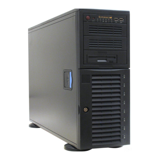
Overview Supermicro's SuperWorkstation 7045A-T/7045A-8 is a high-end dual processor workstation that can be utilized either in a tower or in a rackmount confi guration. The 7045A-T/7045A-8 is comprised of two main subsystems: the SC743TQ-645/ SC743S1-645 high-end server chassis and the X7DAE/X7DA8 dual Intel Xeon processor serverboard. -
Page 12: Serverboard Features
The X7DAE/X7DA8 supports single or dual LGA771 Intel Xeon 5100/5000 series processors. Please refer to the serverboard description pages on our web site for a complete listing of supported processors (http://www.supermicro.com). Memory The X7DAE/X7DA8 has eight 240-pin DIMM slots that can support up to 32 GB of FBD (Fully Buffered DIMM) ECC DDR2-533 SDRAM. -
Page 13: Server Chassis Features
PCI Expansion Slots The X7DAE/X7DA8 has seven PCI expansion slots, which includes two x16 PCI- Express slots (supports SLI), one x4 PCI-Express slot (in a x16 slot), three 64-bit PCI-X slots (which includes two 133/100 MHz slots and one 100 MHz ZCR slot) and one 32-bit 33 MHz PCI slot. -
Page 14: Cooling System
UPER ORKSTATION 7045A-T/7045A-8 User's Manual SCSI Subsystem (7045A-8) The SCSI subsystem supports up to eight 80-pin SCA Ultra320 SCSI hard drives. (Any standard 1" drives are supported. SCA = Single Connection Attachment.) The SCSI drives are connected to a single-channel SCA backplane with SAF-TE. The SCSI drives are also hot-swap units. -
Page 15: System Block Diagram
Figure 1-1. Intel 5000X Chipset: System Block Diagram Note: This is a general block diagram. Please see Chapter 5 for details. PROCESSOR#2 ISL6307 667/1067/1333 MT/S 5000X Greencreek PCI-ExpX16 PCI-Exp X4 PCI-EXP X8 PXH-V ESB2 PCI-X 133 SCSI 7902 1U-IPMI PCI33 MHz CONN System HD Audio... -
Page 16: Contacting Supermicro
UPER ORKSTATION 7045A-T/7045A-8 User's Manual Contacting Supermicro Headquarters Address: SuperMicro Computer, Inc. 980 Rock Ave. San Jose, CA 95131 U.S.A. Tel: +1 (408) 503-8000 Fax: +1 (408) 503-8008 Email: marketing@supermicro.com (General Information) support@supermicro.com (Technical Support) Web Site: www.supermicro.com Europe Address: SuperMicro Computer B.V. -
Page 17: Server Installation
Server Installation 2-1 Overview This chapter provides a quick setup checklist to get your SuperWorkstation 7045A- T/7045A-8 up and running. Following these steps in the order given should enable you to have the system operational within a minimum amount of time. This quick setup assumes that your system has come to you with the processors and memory preinstalled. -
Page 18: Choosing A Setup Location
UPER ORKSTATION 7045A-T/7045A-8 User's Manual Choosing a Setup Location - Leave enough clearance in front of the system to enable you to open the front door completely (~25 inches). - Leave approximately 30 inches of clearance in the back of the system to allow for suffi... -
Page 19: Rack Mounting Considerations
Chapter 2: Server Installation Rack Mounting Considerations Ambient Operating Temperature If installed in a closed or multi-unit rack assembly, the ambient operating tempera- ture of the rack environment may be greater than the ambient temperature of the room. Therefore, consideration should be given to installing the equipment in an environment compatible with the manufacturer’s maximum rated ambient tempera- ture (Tmra). -
Page 20: Installing The System Into A Rack
UPER ORKSTATION 7045A-T/7045A-8 User's Manual Installing the System into a Rack This section provides information on installing the system into a rack unit. Rack installation requires the use of the optional rackmount kit [CSE-PT26(B)]. If the system has already been mounted into a rack or if you are using it as a tower, you can skip ahead to Sections 2-5 and 2-6. -
Page 21: Installing The Chassis Rails
Chapter 2: Server Installation Installing the Chassis Rails You will need to remove the top bezel cover and the feet to add rack rails to the chassis. First, remove the top and right covers (top and left covers when standing as a tower chassis) by fi... -
Page 22: Installing The Rack Rails
UPER ORKSTATION 7045A-T/7045A-8 User's Manual Figure 2-3. Installing the Rails to the Chassis Installing the Rack Rails Determine where you want to place the SuperWorkstation 7045A-T/7045A-8 in the rack. (See Rack and Server Precautions in Section 2-3.) Position the fi xed rack rail/sliding rail guide assemblies at the desired location in the rack, keeping the sliding rail guide facing the inside of the rack. -
Page 23: Installing The Server Into The Rack
Chapter 2: Server Installation Installing the Server into the Rack You should now have rails attached to both the chassis and the rack unit. The next step is to install the server into the rack. You should have two brackets in the rack mount kit. -
Page 24: Checking The Serverboard Setup
UPER ORKSTATION 7045A-T/7045A-8 User's Manual Checking the Serverboard Setup After setting up the the system, you will need to open the unit to make sure the serverboard is properly installed and all the connections have been made. 1. Accessing the inside of the system (see Figure 2-5) (If rack mounted, fi... -
Page 25: Checking The Drive Bay Setup
Checking the Drive Bay Setup Next, you should check to make sure the peripheral drives and the SCSI drives and SCA backplane have been properly installed and all connections have been made. 1. Accessing the drive bays All drives can be accessed from the front of the server. For servicing the DVD- ROM, IDE hard drives and fl... - Page 26 UPER ORKSTATION 7045A-T/7045A-8 User's Manual Figure 2-5. Accessing the Inside of the System (Rack Confi guration shown) 2-10...
-
Page 27: Chapter 3: System Interface
System Interface Overview There are several LEDs on the control panel as well as two for each SATA/SCSI drive carrier and the Ethernet ports. These LEDs are to keep you constantly in- formed of the overall status of the system and the activity and health of specifi c components. -
Page 28: Control Panel Leds
UPER ORKSTATION 7045A-T/7045A-8 User's Manual Control Panel LEDs The control panel located on the front of the SC743TQ-645/SC743S1-645 chassis has six LEDs that provide you with critical information related to different parts of the system. This section explains what each LED indicates when illuminated and any corrective action you may need to take. -
Page 29: Power Fail
Power Fail: Indicates a power supply module has failed. This LED is inended for use with systems that have redundant power supply modules and therefore is not used with the SuperWorkstation 7045A-T/7045A-8. SATA/SCSI Drive Carrier LEDs Each SATA/SCSI drive carrier has two LEDs. Green: When illuminated, the green LED on the front of the SATA/SCSI drive carrier indicates drive activity. - Page 30 UPER ORKSTATION 7045A-T/7045A-8 User's Manual Notes...
-
Page 31: Chapter 4: System Safety
Electrical Safety Precautions Basic electrical safety precautions should be followed to protect yourself from harm and the SuperWorkstation 7045A-T/7045A-8 from damage: Be aware of the locations of the power on/off switch on the chassis as well as the room's emergency power-off switch, disconnection switch or electrical outlet. -
Page 32: General Safety Precautions
UPER ORKSTATION 7045A-T/7045A-8 User's Manual The power supply power cord must include a grounding plug and must be plugged into grounded electrical outlets. Serverboard Battery: CAUTION - There is a danger of explosion if the onboard battery is installed backwards, which will reverse its polarities (see Figure 4-1). -
Page 33: Esd Safety Precautions
Remove any jewelry or metal objects from your body, which are excellent metal conductors that can create short circuits and harm you if they come into contact with printed circuit boards or areas where power is present. After accessing the inside of the system, close the system back up and (if rackmounted) secure it to the rack unit with the retention screws after ensuring that all connections have been made. -
Page 34: Operating Precautions
UPER ORKSTATION 7045A-T/7045A-8 User's Manual For grounding purposes, make sure your computer chassis provides excellent conductivity between the power supply, the case, the mounting fasteners and the serverboard. Operating Precautions Care must be taken to assure that all chassis covers are in place when the SuperWorkstation 7045A-T/7045A-8 is operating to ensure proper cooling. -
Page 35: Chapter 5: Advanced Serverboard Setup
Advanced Serverboard Setup This chapter covers the steps required to install processors and heatsinks to the X7DAE/X7DA8 serverboard, connect the data and power cables and install add- on cards. All serverboard jumpers and connections are described and a layout and quick reference chart are included in this chapter. Remember to close the chassis completely when you have fi... -
Page 36: Processor And Heatsink Installation
UPER ORKSTATION 7045A-T/7045A-8 User's Manual Processor and Heatsink Installation When handling the processor, avoid placing direct pressure on the label area of the fan. Also, do not place the serverboard on a conductive surface, which can damage the BIOS battery and prevent the system from booting up. - Page 37 3. Use your thumb and your index fi nger to hold the CPU at opposite sides. 4. Align pin1 of the CPU (the cor- ner marked with a triangle) with the notched corner of the CPU socket. 5. Find the corner of the CPU that has a semi-circle cutout below a gold dot (CPU key).
-
Page 38: Installing The Heat Sink
UPER ORKSTATION 7045A-T/7045A-8 User's Manual Installing the Heatsink 1. Do not apply any thermal grease to the heatsink or the CPU die; the required amount has already been applied. 2. Place the heatsink on top of the CPU so that the four mounting holes are aligned with those on the (preinstalled) heatsink retention mechanism. -
Page 39: Connecting Cables
Connecting Cables Now that the processors are installed, the next step is to connect the cables to the serverboard. These include the data (ribbon) cables for the peripherals and control panel and the power cables. Connecting Data Cables The ribbon cables used to transfer data from the peripheral devices have been carefully routed in preconfi... -
Page 40: Connecting The Control Panel
UPER ORKSTATION 7045A-T/7045A-8 User's Manual Connecting the Control Panel JF1 contains header pins for various front control panel connectors. See Figure 5-3 for the pin locations of the various front control panel buttons and LED indi- cators. Please note that even and odd numbered pins are on opposite sides of each header. -
Page 41: I/O Ports
I/O Ports The I/O ports are color coded in conformance with the PC 99 specifi cation. See Figure 5-4 below for the colors and locations of the various I/O ports. Figure 5-4. Rear Panel I/O Ports X7DAE/X7DA8 Mouse/ Keyboard USB0/1/2/3 Chapter 5: Advanced Serverboard Setup Parallel Port JLAN1/2... -
Page 42: Installing Memory
UPER ORKSTATION 7045A-T/7045A-8 User's Manual Installing Memory Note: Check the Supermicro web site for recommended memory modules. Exercise extreme care when installing or removing DIMM modules to prevent any possible damage. Also note that the memory is inter- leaved to improve performance (see step 1). -
Page 43: Adding Pci Cards
Chapter 5: Advanced Serverboard Setup Figure 5-5. Installing DIMM into Slot DDR2 FBD DIMM To Install: Insert module vertically and press down until it snaps into place. Pay attention to the bottom notches. To Remove: Use your thumbs to gently push each release tab outward to free the DIMM from the slot. -
Page 44: Serverboard Details
UPER ORKSTATION 7045A-T/7045A-8 User's Manual Serverboard Details Figure 5-6. SUPER X7DA8/X7DAE Layout* Kybd/ FAN6 FAN5 JPW2 Mouse DIMM 4B USB0/1/2/3 DIMM 4A COM1 DIMM 3B DIMM 3A DIMM 2B Parallel Port DIMM 2A DIMM 1B DIMM 1A CD2 CD1 JLAN1/2 JPAC LP IPMI JPG1... -
Page 45: X7Dae/X7Da8 Quick Reference
X7DAE/X7DA8 Quick Reference Jumper Description 3rd Power Fail Detect JBT1 CMOS Clear JCF1 Compact Flash Master/Slave Select C1/2 C to PCI Slot #1 Enable/Disable C3/4 C to PCI Slot #6 Enable/Disable JPA1 SCSI Controller Enable/Disable JPA2/JPA3 SCSI ChA/ChB Termination En/Dis JPAC Audio Enable/Disable JPG1... -
Page 46: Connector Defi Nitions
UPER ORKSTATION 7045A-T/7045A-8 User's Manual Connector Defi nitions ATX Power Connector The power supply connector meets the SSI (Superset ATX) 24-pin specifi - cation. Make sure that the orientation of the connector is correct. See the table on the right for pin defi nitions. Secondary Power Connector In addition to the Primary ATX power... -
Page 47: Hdd Led
HDD LED The HDD (IDE Hard Disk Drive) LED connection is located on pins 13 and 14 of JF1. Attach the IDE hard drive LED cable to display disk activity. Refer to the table on the right for pin defi nitions. NIC1 LED The NIC1 (Network Interface Control- ler) LED connection is located on pins... -
Page 48: Reset Button
UPER ORKSTATION 7045A-T/7045A-8 User's Manual Reset Button The Reset Button connection is lo- cated on pins 3 and 4 of JF1. Attach it to the hardware reset switch on the computer case. Refer to the table on the right for pin defi nitions. Power Button The Power Button connection is located on pins 1 and 2 of JF1. -
Page 49: Serial Ports
Pin# Defi nition P/S 1 Fail Signal P/S 2 Fail Signal P/S 3 Fail Signal Reset Signal Note: This feature is only available when using redundant Supermicro power supplies. Fan Header Pin Defi nitions (Fan1-8) Pin# Defi nition Ground (Black) -
Page 50: Extra Universal Serial Bus Headers
UPER ORKSTATION 7045A-T/7045A-8 User's Manual Extra Universal Serial Bus Headers Two additional USB headers are located near the SATA5 header on the serverboard. This header is designated USB4/5 and is included for connection to the USB ports on the front of the chassis. A USB cable (not included) is needed for the con- nection. -
Page 51: Wake-On-Lan
Wake-On-LAN The Wake-On-LAN header is desig- nated JWOL. See the table on the right for pin defi nitions. You must enable the LAN Wake-Up setting in BIOS to use this feature. You must also have a LAN card with a Wake- on-LAN connector and cable. -
Page 52: Ac'97 Audio
UPER ORKSTATION 7045A-T/7045A-8 User's Manual AC'97 Audio AC'97 provides high quality onboard audio. The X7DAE/X7DA8 features 6-channel sound for front L&R, rear L&R, center and subwoofer speak- ers. This feature is activated with the JPAC jumper. The Line In/Line Out/Mic jacks on the I/O backpanel are used for sound output when AC'97 is enabled (see diagram at right). -
Page 53: Jumper Settings
Jumper Settings Explanation of Jumpers To modify the operation of the serverboard, jumpers can be used to choose between optional settings. Jumpers create shorts between two pins to change the function of the connector. Pin 1 is identifi ed with a square solder pad on the printed circuit board. -
Page 54: Jlan Enable/Disable
UPER ORKSTATION 7045A-T/7045A-8 User's Manual JLAN Enable/Disable Change the setting of jumper JPL1 and JPL2 to enable or disable the on- board LAN ports JLAN1 and JLAN2, respectively. See the table on the right for jumper settings. The default setting is enabled Watch Dog Enable/Disable JWD controls the Watch Dog function. -
Page 55: Scsi Controller Enable/Disable
SCSI Controller Enable/ Disable (X7DA8 only) Jumper JPA1 is used to enable or dis- able the onboard SCSI controller. The default setting is on pins 1-2 to enable SCSI. See the table on the right for jumper settings. SCSI Termination Enable/ Disable (X7DA8 only) Jumpers JPA2/JPA3 are used to en- able or disable termination for the... -
Page 56: Audio Enable/Disable
UPER ORKSTATION 7045A-T/7045A-8 User's Manual Audio Enable/Disable Use JPAC to enable or disable the onboard audio. See the table on the right for jumper settings. The default setting is enabled. C Bus to PCI Jumpers JI C1, JI C2, JI C3 and JI allow you to connect specifi... -
Page 57: 5-10 Onboard Indicators
5-10 Onboard Indicators JLAN1/JLAN2 LEDs Each Ethernet port has two LEDs. One LED indicates activity while the other LED may be green, amber or off to indicate the speed of the con- nection. See the table on the right for the functions associated with the connection speed LED. -
Page 58: 5-11 Parallel Port, Floppy And Hard Drive Connections
UPER ORKSTATION 7045A-T/7045A-8 User's Manual 5-11 Parallel Port, Floppy and Hard Drive Connections Note the following when connecting the fl oppy and hard disk drive cables: • The fl oppy disk drive cable has seven twisted wires. • A red mark on a wire typically designates the location of pin 1. •... -
Page 59: Floppy Connector
Floppy Connector The fl oppy connector is located near the IDE connectors. See the table below for pin defi nitions. SATA Ports There are no jumpers to con- fi gure the onboard SATA con- nectors. See the table on the right for pin defi... -
Page 60: Ide Connectors
UPER ORKSTATION 7045A-T/7045A-8 User's Manual IDE Connectors There are two IDE connectors: IDE#1 (blue) and IDE#2 (white). IDE#1 is designated as the primary IDE drive. IDE#2 is designated as the secondary IDE drive and is reserved for Compact Flash card use only. See the table below for pin defi... -
Page 61: Ultra320 Scsi Connectors
Ultra320 SCSI Connectors (X7DA8 only) There are two SCSI connectors on the serverboard. SCSI Channel A is located at JA1 and SCSI Channel B is located at JA2. Refer to the table at right for the pin defi nitions. Chapter 5: Advanced Serverboard Setup Ultra320 SCSI Drive Connector Pin Defi... - Page 62 UPER ORKSTATION 7045A-T/7045A-8 User's Manual Notes 5-28...
-
Page 63: Chapter 6: Advanced Chassis Setup
Advanced Chassis Setup This chapter covers the steps required to install components and perform simple maintenance on the SC743TQ-645/SC743S1-645 chassis. Following the compo- nent installation steps in the order given will eliminate most common problems. If some steps are unnecessary, skip ahead to the step that follows. Refer to Chapter 2 for instructions on installing the system as a 4U rackmount. - Page 64 UPER ORKSTATION 7045A-T/7045A-8 User's Manual Figure 6-1. Chassis Front View Main Power 5.25" Drive Bays (2) System LEDs System Reset Floppy Drive 6 x SATA Drive Bays (7045A-T) 8 x SCSI Drive Bays (7045A-8) USB Ports...
-
Page 65: Front Control Panel
Front Control Panel The front control panel must be connected to the JF1 connector on the serverboard to provide you with system status and alarm indications. A ribbon cable has bundled these wires together to simplify this connection. Connect the cable from JF1 on the serverboard (making sure the red wire plugs into pin 1) to the appropriate comnnec- tor on the front control panel PCB (printed circuit board). -
Page 66: System Fans
3. Installing a new system fan Replace the failed fan with an identical one (available from Supermicro). Install and reassemble it in the fan housing then plug the housing back into its slot; it should click into place when fully inserted. Check that the fan is working properly and replace the top/left side chassis panel. - Page 67 Chapter 6: Advanced Chassis Setup Figure 6-3. Removing a Chassis Fan Figure 6-4. Removing the Air Shroud...
-
Page 68: Drive Bay Installation
UPER ORKSTATION 7045A-T/7045A-8 User's Manual Drive Bay Installation SATA/SCSI Drives Six SATA or eight SCSI drives may be housed in the SC743TQ-645/SC743S1-645 chassis. The SATA drive IDs are preconfi gured as 0 through 5 in order from right to left (or from bottom to top if rackmounted) and the SCSI drive IDs are preconfi gured as 0 through 7 in order from right to left (or from bottom to top if rackmounted). - Page 69 Figure 6-5. Removing a SATA/SCSI Drive Carrier Figure 6-6. Mounting a SATA/SCSI Drive in a Carrier Important! Regardless of how many SATA/SCSI hard drives are installed, all drive carriers must remain in the drive bays to promote proper airfl ow. 3.
- Page 70 UPER ORKSTATION 7045A-T/7045A-8 User's Manual Figure 6-7. SCSI Backplane SCSI LVD Connector Power Connector Jumper Settings JP19: Buzzer Enable, Closed (On) Enabled (default), Open (Off): Disabled LEDs Drive Fail LEDs: Fail1, Fail2, Fail3, Fail4, Fail5, Fail6, Fail7, Fail8 Activity LEDs: ACT1, ACT2, ACT3, ACT4, ACT5, ACT6, ACT7, ACT8...
-
Page 71: Installing Components In The 5.25" Drive Bays
Chapter 6: Advanced Chassis Setup Installing Components in the 5.25" Drive Bays 1. Drive bay confi guration The 7045A-T/7045A-8 has two 5.25" drive bays. Components such as an extra fl oppy drive, IDE hard drives or CD-ROM drives can be installed in these 5.25" drive bays. -
Page 72: Power Supply
If the power supply unit fails, the system will shut down and you will need to replace the unit. Replacement units can be ordered directly from Supermicro (see contact information in the Preface). As there is only one power supply unit in the 7045A- T/7045A-8, power must be completely removed from the server before removing and replacing the power supply unit for whatever reason. -
Page 73: Chapter 7: Bios
Note: Due to periodic changes to the BIOS, some settings may have been added or deleted and might not yet be recorded in this manual. Please refer to the Manual Download area of the Supermicro web site <http://www.supermicro.com> for any changes to the BIOS that may not be refl ected in this manual. -
Page 74: Running Setup
UPER ORKSTATION 7045A-T/7045A-8 User's Manual Running Setup Note: Default settings are in bold text unless otherwise noted. The BIOS setup options described in this section are selected by choosing the ap- propriate text from the main BIOS Setup screen. All displayed text is described in this section, although the screen display is often all you need to understand how to set the options (see next page). -
Page 75: Main Bios Setup Menu
Chapter 7: BIOS Main BIOS Setup Menu Main Setup Features System Time To set the system date and time, key in the correct information in the appropriate fi elds. Then press the <Enter> key to save the data. System Date Using the arrow keys, highlight the month, day and year fi... - Page 76 UPER ORKSTATION 7045A-T/7045A-8 User's Manual IDE Channel 0 Master/Slave, IDE Secondary Master/Slave These settings allow the user to set the parameters of IDE Channel 0 Master/ Slave, IDE Channel 1 Master/Slave, SATA Port2, SATA Port3 slots. Hit <Enter> to activate the following sub-menu screen for detailed options of these items. Set the correct confi...
- Page 77 CHS Format The following items will be displayed by the BIOS: Type: This item displays the type of IDE or SATA drive. Cylinders: This item indicates the status of cylinders. Headers: This item indicates the number of headers. Sectors: This item displays the number of sectors. Maximum Capacity: This item displays the maximum storage capacity of the system.
- Page 78 UPER ORKSTATION 7045A-T/7045A-8 User's Manual Parallel ATA This setting allows the user to enable or disable the function of Parallel ATA. The options are Disabled and Enabled. Serial ATA This setting allows the user to enable or disable the function of Serial ATA. The options are Disabled and Enabled.
-
Page 79: System Memory
Chapter 7: BIOS System Memory This display informs you how much system memory is recognized as being present in the system. Extended Memory This display informs you how much extended memory is recognized as being present in the system. Advanced Setup Choose Advanced from the Phoenix BIOS Setup Utility main menu with the arrow keys. - Page 80 UPER ORKSTATION 7045A-T/7045A-8 User's Manual Boot Features Quick Boot Mode If enabled, this feature will speed up the POST (Power On Self Test) routine by skipping certain tests after the computer is turned on. The settings are Enabled and Disabled. If Disabled, the POST routine will run at normal speed. Quiet Boot This setting allows you to Enable or Disable the graphic logo screen during boot-up.
-
Page 81: Cache Video Bios Area
Chapter 7: BIOS Memory Cache Cache System BIOS Area This setting allows you to designate a reserve area in the system memory to be used as a System BIOS buffer to allow the BIOS write (cache) its data into this reserved memory area. - Page 82 UPER ORKSTATION 7045A-T/7045A-8 User's Manual Select "Uncached" to disable this function. Select "Write Through" to allow data to be cached into the buffer and written into the system memory at the same time. Select "Write Protect" to prevent data from being written into the base memory area of Block 0-512K.
- Page 83 Enable Master This setting allows you to enable the selected device as the PCI bus master. The options are Enabled and Disabled. Latency Timer This setting allows you to set the clock rate for Bus Master. A high-priority, high- throughout device may benefi t from a greater clock rate. The options are Default, 0020h, 0040h, 0060h, 0080h, 00A0h, 00C0h, and 00E0h.
- Page 84 UPER ORKSTATION 7045A-T/7045A-8 User's Manual Branch 1 Rank Sparing Select enable to enable the sparing feature for Branch 1 of memory bus. The options are Enabled and Disabled. Enhanced x8 Detection Select Enabled to enable Enhanced x8 DRAM UC Error Detection . The options are Disabled and Enabled.
-
Page 85: Advanced Processor Options
Chapter 7: BIOS Advanced Processor Options Access the submenu to make changes to the following settings. CPU Speed This is a display that indicates the speed of the installed processor. Frequency Ratio (Available when supported by the CPU.) The feature allows the user to set the internal frequency multiplier for the CPU. The options are: Default, x12, x13, x14, x15, x16, x17 and x18. - Page 86 UPER ORKSTATION 7045A-T/7045A-8 User's Manual Intel <R> Virtualization Technology CPU.) Select Enabled to use the feature of Virtualization Technology to allow one platform to run multiple operating systems and applications in independent partitions, creating multiple "virtual" systems in one physical computer. The options are Enabled and Disabled.
- Page 87 Base I/O Address This setting allows you to select the base I/O address for serial port B. The options are 3F8, 2F8, 3E8 and 2E8. Interrupt This setting allows you to select the IRQ (interrupt request) for serial port B. The options are IRQ3 and IRQ4.
- Page 88 UPER ORKSTATION 7045A-T/7045A-8 User's Manual DMI Event Logging Access the submenu to make changes to the following settings. Event Log Validity This is a display to inform you of the event log validity. It is not a setting. Event Log Capacity This is a display to inform you of the event log capacity.
- Page 89 Chapter 7: BIOS Console Redirection Access the submenu to make changes to the following settings. COM Port Address This item allows you to specify to redirect the console to Onboard COM A or Onboard COM B. This setting can also be Disabled. BAUD Rate This item allows you to select the BAUD rate for console redirection.
-
Page 90: Voltage Monitoring
UPER ORKSTATION 7045A-T/7045A-8 User's Manual Hardware Monitor Logic CPU Temperature Threshold This option allows the user to set a CPU temperature threshold that will activate the alarm system when the CPU temperature reaches this pre-set temperature threshold. The options are 70 C, 75 C, 80 C and 85... - Page 91 IPMI (Available only when an IPMI card is installed.) IPMI Specifi cation Version: Firmware Version: This item displays the current Firmware Version. System Event Logging Select Enabled to enable IPMI Event Logging. When this function is set to Disabled, the system will continue to log events received via system interface. The options are Enabled and Disabled.
-
Page 92: System Event Log/System Event Log (List Mode)
UPER ORKSTATION 7045A-T/7045A-8 User's Manual OS Boot Watch Dog Set to Enabled to enable OS Boot Watch Dog. The options are Enabled and Disabled. Timer for Loading OS (Minutes) This feature allows the user to set the time value (in minutes) for the previous item: OS Boot Watch Dog by keying-in a desired number in the blank. -
Page 93: Realtime Sensor Data
Chapter 7: BIOS Realtime Sensor Data This feature display information from motherboard sensors, such as temperatures, fan speeds and voltages of various components. 7-21... -
Page 94: Security Settings
UPER ORKSTATION 7045A-T/7045A-8 User's Manual Security Settings Choose Security from the Phoenix BIOS Setup Utility main menu with the arrow keys. You should see the following display. Security setting options are displayed by highlighting the setting using the arrow keys and pressing <Enter>. All Security BIOS settings are described in this section. -
Page 95: Password On Boot
Password on Boot This setting allows you to require a password to be entered when the system boots up. The options are Enabled (password required) and Disabled (password not required). Boot Settings Choose Boot from the Phoenix BIOS Setup Utility main menu with the arrow keys. You should see the following display. -
Page 96: Exit
UPER ORKSTATION 7045A-T/7045A-8 User's Manual Exit Choose Exit from the Phoenix BIOS Setup Utility main menu with the arrow keys. You should see the following display. All Exit BIOS settings are described in this section. Exit Saving Changes Highlight this item and hit <Enter> to save any changes you made and to exit the BIOS Setup utility. -
Page 97: Appendix A: Bios Post Messages
Appendix A: BIOS POST Messages Appendix A BIOS POST Messages During the Power-On Self-Test (POST), the BIOS will check for problems. If a prob- lem is found, the BIOS will activate an alarm or display a message. The following is a list of such BIOS messages. - Page 98 UPER ORKSTATION 7045A-T/7045A-8 User's Manual System CMOS checksum bad - Default confi guration used System CMOS has been corrupted or modifi ed incorrectly, perhaps by an application program that changes data stored in CMOS. The BIOS installed Default Setup Values. If you do not want these values, enter Setup and enter your own values.
- Page 99 Appendix A: BIOS POST Messages System cache error - Cache disabled RAM cache failed and BIOS disabled the cache. On older boards, check the cache jumpers. You may have to replace the cache. See your dealer. A disabled cache slows system performance considerably.
- Page 100 UPER ORKSTATION 7045A-T/7045A-8 User's Manual Invalid System Confi guration Data Problem with NVRAM (CMOS) data. I/O device IRQ confl ict I/O device IRQ confl ict error. PS/2 Mouse Boot Summary Screen: PS/2 Mouse installed. nnnn kB Extended RAM Passed Where nnnn is the amount of RAM in kilobytes successfully tested. nnnn Cache SRAM Passed Where nnnn is the amount of system cache in kilobytes successfully tested.
- Page 101 Appendix A: BIOS POST Messages Press <F1> to resume, <F2> to Setup, <F3> for previous Displayed after any recoverable error message. Press <F1> to start the boot process or <F2> to enter Setup and change the settings. Press <F3> to display the previous screen (usually an initialization error of an Option ROM, i.e., an add-on card).
- Page 102 UPER ORKSTATION 7045A-T/7045A-8 User's Manual Notes...
-
Page 103: Appendix B: Bios Post Codes
Appendix B BIOS POST Codes This section lists the POST (Power On Self Test) codes for the PhoenixBIOS. POST codes are divided into two categories: recoverable and terminal. Recoverable POST Errors When a recoverable type of error occurs during POST, the BIOS will display a POST code that describes the problem. - Page 104 UPER ORKSTATION 7045A-T/7045A-8 User's Manual POST Code Description 8254 timer initialization 8237 DMA controller initialization Reset Programmable Interrupt Controller 1-3-1-1 Test DRAM refresh 1-3-1-3 Test 8742 Keyboard Controller Set ES segment register to 4 GB Auto size DRAM Initialize POST Memory Manager Clear 512 kB base RAM 1-3-4-1 RAM failure on address line xxxx* 1-3-4-3 RAM failure on data bits xxxx* of low byte of memory bus...
- Page 105 POST Code Description Test RAM between 512 and 640 kB Test extended memory Test extended memory address lines Jump to UserPatch1 Confi gure advanced cache registers Initialize Multi Processor APIC Enable external and CPU caches Setup System Management Mode (SMM) area Display external L2 cache size Load custom defaults (optional) Display shadow-area message...
- Page 106 UPER ORKSTATION 7045A-T/7045A-8 User's Manual POST Code Description Check for SMART Drive (optional) Shadow option ROMs Set up Power Management Initialize security engine (optional) Enable hardware interrupts Determine number of ATA and SCSI drives Set time of day Check key lock Initialize typematic rate Erase F2 prompt Scan for F2 key stroke...
- Page 107 POST Code Description Re-map I/O and memory for PCMCIA Initialize digitizer and display message Unknown interrupt The following are for boot block in Flash ROM POST Code Description Initialize the chipset Initialize the bridge Initialize the CPU Initialize system timer Initialize system I/O Check force recovery boot Checksum BIOS ROM...
- Page 108 UPER ORKSTATION 7045A-T/7045A-8 User's Manual Notes...
-
Page 109: Appendix C: Software Installation
RAID Utility program to confi gure the RAID Level that you desire before installing the Windows XP/2000/2003 operating system and other software drivers. (The necessary drivers are all included on the Supermicro CD that came packaged with your motherboard.) Note that the current version of the ESB2 SATA RAID Utility can only support Windows XP/2000/2003 Operating Systems. -
Page 110: Raid Configurations
UPER ORKSTATION 7045A-T/7045A-8 User's Manual RAID Confi gurations The following types of RAID confi gurations are supported: RAID 0 (Data Striping): this writes data in parallel, interleaved ("striped") sections of two hard drives. Data transfer rate is doubled over using a single disk. RAID1 (Data Mirroring): an identical data image from one drive is copied to another drive. - Page 111 Using the Intel ESB2 SATA RAID Utility Program 1. Creating, Deleting and Resetting RAID Volumes: a. After the system exits from the BIOS Setup Utility, the system will automatically reboot. The following screen appears after Power-On Self Test. b. When you see the above screen, press the <Ctrl> and the <I> keys simultane- ously to have the main menu of the SATA RAID Utility appear: Note: All graphics and screen shots shown in the manual are for reference only.
-
Page 112: Creating A Raid 0 Volume
UPER ORKSTATION 7045A-T/7045A-8 User's Manual Creating a RAID 0 Volume . Select "Create RAID Volume" from the main menu and press the <Enter> key. The following screen will appear: 2. Specify a name for the RAID 0 set and press the <Tab> key or the <Enter> key to go to the next fi... -
Page 113: Creating A Raid 1 Volume
Appendix C: Software Installation Creating a RAID 1 Volume 1. Select "Create RAID Volume" from the main menu and press the <Enter> key. The following screen will appear: 2. Specify a name for the RAID 1 set and press the <Tab> key or the <Enter> key to go to the next fi... - Page 114 UPER ORKSTATION 7045A-T/7045A-8 User's Manual Creating a RAID 10 (RAID 1+ RAID 0) . Select "Create RAID Volume" from the main menu and press the <Enter> key. The following screen will appear: 2. Specify a name for the RAID 10 set and press <Enter>. 3.
-
Page 115: Creating A Raid 5 Set (Parity)
Appendix C: Software Installation Creating a RAID 5 Set (Parity) . Select "Create RAID Volume" from the main menu and press the <Enter> key. The following screen will appear: 2. Specify a name for the RAID 5 set and press <Enter>. 3. -
Page 116: Deleting A Raid Volume
UPER ORKSTATION 7045A-T/7045A-8 User's Manual Deleting a RAID Volume Warning: Be sure to back up your data before deleting a RAID set. You will lose all data on the disk drives when deleting a RAID set. 1. From the main menu, select item2-Delete RAID Volume, and press <Enter>. 2. -
Page 117: Exiting The Intel Matrix Storage Manager Utility
Resetting to Non-RAID and Resetting a RAID HDD Warning: Be cautious when you reset a RAID volume HDD to non- RAID or Resetting a RAID HDD. Resetting a RAID volume HDD or Resetting a RAID HDD will reformat the HDD and delete the internal RAID structure on the drive. - Page 118 8. After the Windows XP/2000/2003 installation is completed, the system will au- tomatically reboot. 9. Insert the Supermicro CD that came with the package into the CD drive during system reboot, and the following screen will appear (next page): Note: the current version of the ESB2 SATA RAID Utility can only support Windows XP/2000/2003 Operating System.
- Page 119 After all the hardware has been installed, you must fi rst install the operating system and then other software drivers. The necessary drivers are all included on the Supermicro CDs that came packaged with your motherboard. Driver/Tool Installation Display Screen Note: Click the icons showing a hand writing on paper to view the readme fi...
- Page 120 UPER ORKSTATION 7045A-T/7045A-8 User's Manual Supero Doctor III The Supero Doctor III program is a Web base management tool that supports remote management capability. It includes Remote and Local Management tools. The local management is called SD III Client. The Supero Doctor III program included on the CDROM that came with your motherboard allows you to monitor the environment and operations of your system.
- Page 121 Supero Doctor III: Remote Control Screen Note: SD III Software Revision 1.0 can be downloaded from our Web Site at: ftp:// ftp.supermicro.com/utility/Supero_Doctor_III/. You can also download SDIII User's Guide at: http://www.supermicro.com/PRODUCT/Manuals/SDIII/UserGuide.pdf. For Linux, we will still recommend Supero Doctor II.
- Page 122 UPER ORKSTATION 7045A-T/7045A-8 User's Manual Notes C-14...
-
Page 123: Appendix D: System Specifi Cations
Single or dual 604-pin Intel Xeon processors at a front side (system) bus speed of 1333/1066 MHz. (Please refer to the support section of our web site for a complete listing of supported processors: (http://www.supermicro.com). Chipset Intel 5000X chipset BIOS ®... - Page 124 UPER ORKSTATION 7045A-T/7045A-8 User's Manual Serverboard Model: X7DAE/X7DA8 Form Factor: Extended ATX Dimensions: 12 x 13.05 in (305 x 332 mm) Chassis Model: SC743TQ-645/SC743S1-645 Form Factor: tower/4U rackmount Dimensions: (WxHxD as 4U) 6.94" x 17.125 x 24.125 in. (17.6 x 435 x 612.8 Weight Gross (Bare Bone): 63 lbs.
-
Page 125: Regulatory Compliance
Appendix D: System Specifi cations Regulatory Compliance Electromagnetic Emissions: FCC Class B, EN 55022 Class B, EN 61000-3-2/-3-3, CISPR 22 Class B Electromagnetic Immunity: EN 55024/CISPR 24, (EN 61000-4-2, EN 61000-4-3, EN 61000-4-4, EN 61000-4-5, EN 61000-4-6, EN 61000-4-8, EN 61000-4-11) Safety: EN 60950/IEC 60950-Compliant UL Listed (USA) - Page 126 UPER ORKSTATION 7045A-T/7045A-8 User's Manual Notes...
Need help?
Do you have a question about the SuperWorkstation 7045A-8 and is the answer not in the manual?
Questions and answers