Table of Contents
Advertisement
Quick Links
Advertisement
Table of Contents

Subscribe to Our Youtube Channel
Related Manuals for Supero SuperWorkstation 7046A-6


Summary of Contents for Supero SuperWorkstation 7046A-6
- Page 1 UPER ® 7046A-6 uper orkstation USER’S MANUAL...
- Page 2 The information in this User’s Manual has been carefully reviewed and is believed to be accurate. The vendor assumes no responsibility for any inaccuracies that may be contained in this document, makes no commitment to update or to keep current the information in this manual, or to notify any person or organization of the updates.
-
Page 3: About This Manual
SuperWorkstation 7046A- 6. Installation and maintenance should be performed by experienced technicians only. The SuperWorkstation 7046A-6 is a high-end system based on the SC743TS- 865BP-SQ tower/4U rackmount chassis and the X8DA6 serverboard. Manual Organization Chapter 1: Introduction The fi... - Page 4 uper orkstation 7046A-6 User's Manual Chapter 5: Advanced Serverboard Setup Chapter 5 provides detailed information on the X8DA6 serverboard, including the locations and functions of connections, headers and jumpers. Refer to this chapter when adding or removing processors or main memory and when reconfi guring the serverboard.
- Page 5 Preface Notes...
-
Page 6: Table Of Contents
uper orkstation 7046A-6 User's Manual Table of Contents Chapter 1 Introduction Overview ......................1-1 Serverboard Features ..................1-2 Processors ...................... 1-2 Memory ......................1-2 Serial ATA ....................... 1-2 SAS ........................ 1-2 PCI Expansion Slots ..................1-2 Onboard Controllers/Ports ................1-3 Other Features .................... - Page 7 Table of Contents Installing the System into the Rack ..............2-7 Checking the Serverboard Setup ..............2-8 Checking the Drive Bay Setup ................ 2-9 Chapter 3 System Interface Overview ......................3-1 Control Panel Buttons ..................3-1 Power ......................3-1 Reset ....................... 3-1 Control Panel LEDs ..................
- Page 8 5-12 Floppy, SAS and SATA Ports ................ 5-23 5-13 Installing Additional Drivers ................5-24 5-14 Supero Doctor III ................... 5-25 Chapter 6 Advanced Chassis Setup Static-Sensitive Devices .................. 6-1 Precautions ..................... 6-1 Unpacking ....................... 6-1 Front Control Panel ..................6-3 System Fans ....................
-
Page 9: Chapter 1 Introduction
SC743TS-865BP-SQ tower/4U chassis and the X8DA6 dual Intel® Xeon® proces- sor serverboard. Please refer to our web site for information on operating systems that have been certifi ed for use with the SuperWorkstation 7046A-6 (www.super- micro.com). In addition to the serverboard and chassis, various hardware components have been included with the SuperWorkstation 7046A-6, as listed below: •... -
Page 10: Serverboard Features
7046A-6 User's Manual Serverboard Features At the heart of the SuperWorkstation 7046A-6 lies the X8DA6, a dual processor serverboard based on the Intel 5520 + ICH10R chipset. Below are the main features of the X8DA6. (See Figure 1-1 for a block diagram of the chipset). -
Page 11: Onboard Controllers/Ports
CPU overheat sensors, virus protection and BIOS rescue. Chassis Features The SuperWorkstation 7046A-6 is a scaleable system designed with today's most state-of-the-art features. The following is a general outline of the main features of the SC743TS-865BP-SQ chassis. -
Page 12: Cooling System
uper orkstation 7046A-6 User's Manual Cooling System The SC743TS-865BP-SQ chassis has an innovative "Super Quiet" cooling design that provides suffi cient cooling at very low noise level - ideal for a workplace envi- ronment. The chassis includes two 8-cm hot-plug PWM (Pulse Width Modulation) system cooling fans located in the middle of the chassis. -
Page 13: System Block Diagram
Chapter 1: Introduction Figure 1-1. Intel 5520 Chipset: System Block Diagram Note: This is a general block diagram. Please see Chapter 5 for details. #1-6 #1-5 #0-6 #1-4 #0-5 #1-3 #0-4 #1-2 #0-3 #0-2 #1-1 #0-1 PCI-E x9 CPU#2 CPU#1 Slot 1 PCI-X 133/100 PCI-E x8... -
Page 14: Contacting Supermicro
uper orkstation 7046A-6 User's Manual Contacting Supermicro Headquarters Address: Super Micro Computer, Inc. 980 Rock Ave. San Jose, CA 95131 U.S.A. Tel: +1 (408) 503-8000 Fax: +1 (408) 503-8008 Email: marketing@supermicro.com (General Information) support@supermicro.com (Technical Support) Web Site: www.supermicro.com Europe Address: Super Micro Computer B.V. -
Page 15: Chapter 2 Installation
Installation Overview This chapter provides a quick setup checklist to get your SuperWorkstation 7046A-6 up and running. Following these steps in the order given should enable you to have the system operational within a minimum amount of time. This quick setup assumes that your system has come to you with the processor and memory preinstalled. -
Page 16: Choosing A Setup Location
uper orkstation 7046A-6 User's Manual Choosing a Setup Location • Leave enough clearance in front of the rack to enable you to open the front door completely (~25 inches) and approximately 30 inches of clearance in the back of the rack to allow for suffi cient airfl ow and ease in servicing. •... -
Page 17: Rack Mounting Considerations
Chapter 2: Installation • Allow the hot plug SAS/SATA drives and power supply modules to cool before touching them. • Always keep the rack's front door and all panels and components on the servers closed when not servicing to maintain proper cooling. Rack Mounting Considerations Ambient Operating Temperature If installed in a closed or multi-unit rack assembly, the ambient operating tempera-... -
Page 18: Installing The System Into A Rack
uper orkstation 7046A-6 User's Manual Installing the System into a Rack This section provides information on installing the system into a rack unit. Rack installation requires the use of the optional rackmount kit. If the system has already been mounted into a rack or if you are using it as a tower, you can skip ahead to Sections 2-5 and 2-6. -
Page 19: Installing The Chassis Rails
Chapter 2: Installation Installing the Chassis Rails You will need to remove the top cover and the feet to add rack rails to the chassis. First, remove the top and right covers (top and left covers when standing as a tower chassis) by fi... -
Page 20: Installing The Rack Rails
Figure 2-3. Installing the Rails to the Chassis Installing the Rack Rails Determine where you want to place the SuperWorkstation 7046A-6 in the rack. (See Rack and Server Precautions in Section 2-3.) Position the fi xed rack rail/sliding rail guide assemblies at the desired location in the rack, keeping the sliding rail guide facing the inside of the rack. -
Page 21: Installing The System Into The Rack
Chapter 2: Installation Installing the System into the Rack You should now have rails attached to both the chassis and the rack unit. The next step is to install the system into the rack. You should have two brackets in the rack mount kit. -
Page 22: Checking The Serverboard Setup
uper orkstation 7046A-6 User's Manual Checking the Serverboard Setup After setting up the the system, you will need to open the unit to make sure the serverboard is properly installed and all the connections have been made. Accessing the Inside of the System If rack mounted, grasp the two handles on either side and pull the unit straight out until it locks (you will hear a "click"). -
Page 23: Checking The Drive Bay Setup
Chapter 2: Installation Figure 2-5. Accessing the Inside of the System (Rack Confi guration shown) Checking the Drive Bay Setup Next, you should check to make sure the peripheral drives and the SAS/SATA drives and backplane have been properly installed and all connections have been made. - Page 24 uper orkstation 7046A-6 User's Manual Depending upon your system's confi guration, your system may have one or more drives already installed. If you need to install SAS/SATA drives, please refer to Chapter 6. Checking the Airfl ow Airfl ow is provided by four hot-swap 8-cm chassis fans working in conjunction with an air shroud.
-
Page 25: Chapter 3 System Interface
Chapter 3: System Interface Chapter 3 System Interface Overview The control panel on the 7046A-6 has several LEDs and two buttons. There are also two LEDs on each SAS/SATA drive carrier. These LEDs keep you constantly informed of the overall status of the system and the activity and health of specifi c components. -
Page 26: Control Panel Leds
uper orkstation 7046A-6 User's Manual Control Panel LEDs The control panel located on the front of the SC743TS-865BP-SQ chassis has six LEDs that provide you with critical information related to different parts of the system. This section explains what each LED indicates when illuminated and any corrective action you may need to take. -
Page 27: Power Fail
Chapter 3: System Interface airfl ow in the system or the ambient room temperature being too warm. Check the routing of the cables and make sure all fans are present and operating normally. You should also check to make sure that the chassis covers are installed. Finally, verify that the heatsinks are installed properly (see Chapter 5). - Page 28 uper orkstation 7046A-6 User's Manual Notes...
-
Page 29: Chapter 4 System Safety
System Safety Electrical Safety Precautions Basic electrical safety precautions should be followed to protect yourself from harm and the SuperWorkstation 7046A-6 from damage: • Be aware of the locations of the power on/off switch on the chassis as well as the room's emergency power-off switch, disconnection switch or electrical outlet. -
Page 30: General Safety Precautions
Contact technical support for details and support. General Safety Precautions Follow these rules to ensure general safety: • Keep the area around the SuperWorkstation 7046A-6 clean and free of clut- ter. • The 7046A-6 weighs approximately 64 lbs (29.1 kg.) when fully loaded. When lifting the system, two people at either end should lift slowly with their feet spread out to distribute the weight. -
Page 31: Esd Precautions
Chapter 4: System Safety • Remove any jewelry or metal objects from your body, which are excellent metal conductors that can create short circuits and harm you if they come into contact with printed circuit boards or areas where power is present. •... -
Page 32: Operating Precautions
uper orkstation 7046A-6 User's Manual Operating Precautions Care must be taken to assure that the chassis cover is in place when the 7046A- 6 is operating to assure proper cooling. Out of warranty damage to the 7046A-6 system can occur if this practice is not strictly followed. Figure 4-1. -
Page 33: Chapter 5 Advanced Serverboard Setup
Chapter 5: Advanced Serverboard Setup Chapter 5 Advanced Serverboard Setup This chapter covers the steps required to install the X8DA6 serverboard into the chassis, connect the data and power cables and install add-on cards. All serverboard jumpers and connections are also described. A layout and quick reference chart are included in this chapter for your reference. -
Page 34: Unpacking
uper orkstation 7046A-6 User's Manual Unpacking The serverboard is shipped in antistatic packaging to avoid electrical static dis- charge. When unpacking the board, make sure the person handling it is static protected. Serverboard Installation This section explains the fi rst step of physically mounting the X8DA6 into the SC743TS-865BP-SQ chassis. -
Page 35: Connecting Cables
Chapter 5: Advanced Serverboard Setup Connecting Cables Now that the serverboard is installed, the next step is to connect the cables to the board. These include the data (ribbon) cables for the peripherals and control panel and the power cables. Connecting Data Cables The cables used to transfer data from the peripheral devices have been carefully routed to prevent them from blocking the fl... -
Page 36: I/O Ports
uper orkstation 7046A-6 User's Manual Figure 5-1. Control Panel Header Pins Ground x (Key) x (Key) Power On LED HDD LED NIC1 LED NIC2 LED OH/Fan Fail LED Power Fail LED Ground Reset (Button) Ground Power (Button) I/O Ports The I/O ports are color coded in conformance with the PC 99 specifi cation. See Figure 5-2 below for the colors and locations of the various I/O ports. -
Page 37: Processor And Heatsink Installation
Chapter 5: Advanced Serverboard Setup Processor and Heatsink Installation When handling the processor package, avoid placing direct pressure on the label area of the fan. Notes: • Always connect the power cord last and always remove it before adding, re- moving or changing any hardware components. - Page 38 uper orkstation 7046A-6 User's Manual After removing the plastic cap, using your thumb and the index fi nger, hold the CPU at the north and south center edges. Align the CPU key (the semi-circle cutout) against the socket key (the notch below the gold color dot on the side of the socket).
- Page 39 Chapter 5: Advanced Serverboard Setup Installation and Removal of the Heatsink Installing the Heatsink Installation Do not apply any thermal grease to the heatsink or the CPU die; the required amount has already been applied. Screw #1 Place the heatsink on top of the CPU so that the four mounting holes are aligned with those on the retention mechanism.
-
Page 40: Installing Memory Modules
uper orkstation 7046A-6 User's Manual Installing Memory Modules Note: Check the Supermicro web site for recommended memory modules. CAUTION Exercise extreme care when installing or removing DIMM modules to prevent any possible damage. Installing & Removing DIMMs Press down the release tabs Insert the desired number of DIMMs into the memory slots, starting with P1-DIMM 1A. -
Page 41: Memory Support
Chapter 5: Advanced Serverboard Setup Memory Support The X8DA6 supports up to 96 GB of registered ECC or up to 24 GB of unbuffered ECC/non ECC DDR3-1333/1066/800 in 12 slots. Memory speed support is depen- dent on the type of CPU used. DIMM Module Population Confi... -
Page 42: Adding Pci Add-On Cards
uper orkstation 7046A-6 User's Manual Adding PCI Add-On Cards The 7046A-6 can accommodate standard size add-on cards populated in all slots on the X8DA6 serverboard. Installing an Add-on Card Begin by removing the PCI slot shield for the slot you wish to populate. Fully seat the card into the riser card slot, pushing down with your thumbs evenly on both sides of the card. -
Page 43: Serverboard Details
Chapter 5: Advanced Serverboard Setup Serverboard Details Figure 5-3. X8DA6 Layout FAN5 P1-DIMM3A JPI2C1 JPW3 KB/MS JPW2 JPW1 P1-DIMM3B FAN6 FAN1 P1-DIMM2A 0/1/2/3 P1-DIMM2B P1-DIMM1A P1-DIMM1B FAN7/CPU2 CPU2 FAN8 (CPU1 Fan) CPU1 P2-DIMM1B LAN1/2 FAN2 P2-DIMM1A P2-DIMM2B JOH1 HD Audio P2-DIMM2A P2-DIMM3B P2-DIMM3A... -
Page 44: X8Da6 Quick Reference
uper orkstation 7046A-6 User's Manual X8DA6 Quick Reference Jumper Description Default Setting JBT1 CMOS Clear (See Section 5-10) C1/JI C2 SMB (I C) to PCI-X Slots Pins 2-3 (Disabled) Audio Mode Select Off (HD Mode) JPAC1 Audio Enable/Disable Pins 1-2 (Enabled) JPL1/JPL2 LAN 1/2 En/Dis (For PCB Rev.1.31 or later) Pins 1-2 (Enabled) -
Page 45: Connector Defi Nitions
Chapter 5: Advanced Serverboard Setup Connector Defi nitions ATX Power 24-pin Connector Pin Defi nitions Pin# Defi nition Pin # Defi nition Main ATX Power Supply +3.3V +3.3V Connector -12V +3.3V The primary power supply connector (JPW3) meets the SSI (Superset ATX) PS_ON 24-pin specifi... - Page 46 uper orkstation 7046A-6 User's Manual NIC1 (GLAN) LED NIC1 LED The LED connections for the GB LAN Pin Defi nitions port are on pins 11 and 12 of JF1. At- Pin# Defi nition tach an LED cable to display network activity.
- Page 47 Chapter 5: Advanced Serverboard Setup Fan Headers The X8DA6/X8DAE has six fan head- ers (Fan1 to Fan6) and two CPU fan Fan Header headers (Fan7/Fan8). All these 4-pin Pin Defi nitions fans headers are backward compat- Pin# Defi nition ible with traditional 3-pin fans. How- Ground (Black) ever, fan speed control is available for +12V (Red)
- Page 48 uper orkstation 7046A-6 User's Manual Speaker On the JD1 header, pins 3~4 are used Speaker Connector for the internal speaker. Close pins Pin Defi nitions 3~4 to use the onboard speaker. If Pin Setting Defi nition you wish to use an external speaker, Pins 3~4 Internal Speaker connect the speaker cable to pins...
- Page 49 Chapter 5: Advanced Serverboard Setup Front Panel Audio Control Front Panel Audio (HD Rev. 1.2) When front panel headphones are Pin Defi nitions plugged in, the back panel audio output Pin# Defi nition is disabled. This is done through the FP MIC left channel Audio header (Audio FP).
- Page 50 uper orkstation 7046A-6 User's Manual CNF1 Pin Defi nitions Pin# Defi n. Defi n PTPA0+ PTPA0- PTPB0+ PTPB0- IEEE 1394 Connectors Connectors CNF1 and CNF2 provide 1394 1394 connectivity for IEEE 1394 (FireWire) devices. See the tables on the right CNF2 Pin Defi...
-
Page 51: 5-10 Jumper Settings
Chapter 5: Advanced Serverboard Setup 5-10 Jumper Settings Explanation of Jumpers To modify the operation of the serverboard, jumpers can be used Connector to choose between optional settings. Pins Jumpers create shorts between two pins to change the function of the con- nector. - Page 52 uper orkstation 7046A-6 User's Manual LAN1/LAN2 Enable/Disable LAN1/LAN2 Enable/Disable Change the setting of jumper JPL1 or Jumper Settings JPL2 to enable or disable the LAN1 and Jumper Setting Defi nition LAN2 Ethernet ports, respectively. See Pins 1-2 Enabled the table on the right for jumper set- Pins 2-3 Disabled tings.
- Page 53 Chapter 5: Advanced Serverboard Setup 1394a (FireWire) Enable/Disable 1394a Enable/Disable Jumper Settings JPI1 allows the user to use the onboard Pin# Defi nition IEEE CNF1 and CNF2 connections. Enabled Close pins 1-2 to enable FireWire use. Disabled The default setting is enabled. SAS Enable/Disable SAS Enable/Disable Jumper JPS1 allows you to enable or...
-
Page 54: 5-11 Onboard Indicators
uper orkstation 7046A-6 User's Manual 5-11 Onboard Indicators LAN1/2 LEDs LAN1/2 LED The Ethernet ports (located beside (Connection Speed Indicator) the VGA port) have two LEDs. On LED Color Defi nition each port, one LED indicates activity No Connection or 10 Mb/s while the other LED may be green, Green 100 Mb/s... -
Page 55: 5-12 Floppy, Sas And Sata Ports
Chapter 5: Advanced Serverboard Setup 5-12 Floppy, SAS and SATA Ports Floppy Connector Floppy Drive Connector The fl oppy connector is located be- Pin Defi nitions tween the COM port and FireWire Pin# Defi nition Pin # Defi nition headers on the motherboard. See the Ground FDHDIN table on the right for pin defi... -
Page 56: 5-13 Installing Additional Drivers
uper orkstation 7046A-6 User's Manual 5-13 Installing Additional Drivers After you've installed the Windows Operating System, a screen as shown below will appear. You are ready to install software programs and drivers that have not yet been installed. To install these software programs and drivers, click the icons to the right of these items. -
Page 57: Supero Doctor Iii
The Supero Doctor III program is a Web-based management tool that supports remote management capability. It includes Remote and Local Management tools. The local management is called the SD III Client. The Supero Doctor III program included on the CDROM that came with your motherboard allows you to monitor the environment and operations of your system. - Page 58 7046A-6 User's Manual Note: SD III Software Revision 1.0 can be downloaded from our Web site at: ftp:// ftp.supermicro.com/utility/Supero_Doctor_III/. You can also download SDIII User's Guide at: http://www.supermicro.com/PRODUCT/Manuals/SDIII/UserGuide.pdf. For Linux, we will still recommend that you use Supero Doctor II. 5-26...
-
Page 59: Chapter 6 Advanced Chassis Setup
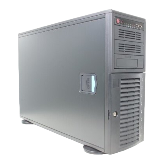
Chapter 6: Advanced Chassis Setup Chapter 6 Advanced Chassis Setup This chapter covers the steps required to install components and perform simple maintenance on the SC743TS-865BP-SQ chassis. Following the component in- stallation steps in the order given will eliminate most common problems. If some steps are unnecessary, skip ahead to the step that follows. - Page 60 uper orkstation 7046A-6 User's Manual Figure 6-1. Chassis Front View Main Power System Reset USB Ports 5.25" Drive Bays (3) 8 SAS Drive Bays (behind locking bezel)
-
Page 61: Front Control Panel
Chapter 6: Advanced Chassis Setup Front Control Panel The front control panel must be connected to the JF1 connector on the serverboard to provide you with system status and alarm indications. A ribbon cable has bundled these wires together to simplify this connection. Connect the cable from JF1 on the serverboard (making sure the red wire plugs into pin 1) to the appropriate comnnector on the front control panel PCB (printed circuit board). -
Page 62: System Fans
uper orkstation 7046A-6 User's Manual System Fans Two 8-cm PWM chassis fans provide air intake while one 9-cm PWM exhaust fan expels hot air from the chassis. All are low-noise fans that result in "Whisper-Quiet" operation (~28 dB). The chassis is also fi tted with an air shroud to concentrate the fl... - Page 63 Chapter 6: Advanced Chassis Setup Figure 6-3. Removing a Chassis Fan...
-
Page 64: Drive Bay Installation
uper orkstation 7046A-6 User's Manual Drive Bay Installation A total of eight SAS (or six SATA) drives may be housed in the SC743TS-865BP- SQ chassis. The drive IDs are preconfi gured as 0 through 7 (or 5) in order from bottom to top (or from left to right if rackmounted). -
Page 65: Sas/Sata Backplane
Chapter 6: Advanced Chassis Setup Figure 6-4. Removing a SAS/SATA Drive Carrier Figure 6-5. Mounting a SAS/SATA Drive in a Carrier Important! Use extreme caution when working around the SAS/ SATA backplane. Do not touch the backplane with any metal objects and make sure no ribbon cables touch the backplane or obstruct the airfl... -
Page 66: Installing Components In The 5.25" Drive Bays
uper orkstation 7046A-6 User's Manual Installing Components in the 5.25" Drive Bays The 7046A-6 has three 5.25" drive bays. Components such as SATA hard drives or DVD/CD-ROM drives can be installed into these 5.25" drive bays. Removing the Empty Drive Bay First power down the system. -
Page 67: Power Supply
Chapter 6: Advanced Chassis Setup Power Supply The SuperWorkstation 7046A-6 has a single 865 watt power supply. This power unit is equipped with low-noise technology, making the system ideal for workstation environments. The power supply has an auto-switching capability that enable it to automatically sense and operate with 100 or 240 volt inputs. - Page 68 uper orkstation 7046A-6 User's Manual Notes 6-10...
-
Page 69: Chapter 7 Bios
Chapter 7: BIOS Chapter 7 BIOS Introduction This chapter describes the AMI BIOS Setup Utility for the X8DA6. The AMI ROM BIOS is stored in a Flash EEPROM and can be easily updated. This chapter de- scribes the basic navigation of the AMI BIOS Setup Utility setup screens. Note: For instructions on BIOS recovery, please refer to the instruction guide posted at http://www.supermicro.com/support/manuals/. -
Page 70: Starting The Setup Utility
uper orkstation 7046A-6 User's Manual Starting the Setup Utility Normally, the only visible Power-On Self-Test (POST) routine is the memory test. As the memory is being tested, press the <Delete> key to enter the main menu of the AMI BIOS Setup Utility. From the main menu, you can access the other setup screens. - Page 71 Chapter 7: BIOS Supermicro X8DA6 • BIOS Build Version: This item displays the BIOS revision used in your sys- tem. • BIOS Build Date: This item displays the date when this BIOS was built. • AMI BIOS Core Version: This item displays the revision number of the AMI BIOS Core upon which your BIOS was built.
-
Page 72: Advanced Setup Confi Gurations
uper orkstation 7046A-6 User's Manual Advanced Setup Confi gurations Use the arrow keys to select Boot Setup and hit <Enter> to access the submenu items. Boot Features Quick Boot If enabled, this option will skip certain tests during POST to reduce the time needed for system boot. - Page 73 Chapter 7: BIOS Interrupt 19 Capture Interrupt 19 is the software interrupt that handles the boot disk function. When this item is set to Enabled, the ROM BIOS of the host adaptors will "capture" Interrupt 19 at boot and allow the drives that are attached to these host adaptors to function as bootable disks.
- Page 74 uper orkstation 7046A-6 User's Manual C1E Support Select Enabled to use the feature of Enhanced Halt State. C1E signifi cantly reduces the CPU's power consumption by reducing the CPU's clock cycle and voltage during a "Halt State." The options are Disabled and Enabled. Hardware Prefetcher (Available when supported by the CPU) If this item is set to Enabled, the hardware prefetcher will prefetch streams of data and instructions from the main memory to the L2 cache in the forward or backward...
- Page 75 Chapter 7: BIOS Simultaneous Multi-Threading (Available when supported by the CPU) Set to Enabled to use the Simultaneous Multi-Threading Technology, which will result in increased CPU performance. The options are Disabled and Enabled. Active Processor Cores Set to Enabled to use a processor's Second Core and beyond. (Please refer to Intel's web site for more information.) The options are All, 1 and 2.
-
Page 76: Advanced Chipset Control
uper orkstation 7046A-6 User's Manual Advanced Chipset Control The items included in the Advanced Settings submenu are listed below: CPU Bridge Confi guration QPI Links Speed This feature selects QPI's data transfer speed. The options are Slow-mode, and Full Speed. QPI Frequency This selects the desired QPI frequency. - Page 77 Chapter 7: BIOS If the item above is enabled, the following items will display. Hysteresis Temperature (Closed Loop Only) Temperature Hysteresis is the temperature lag (in degrees Celsius) after the predefi ned DIMM temperature threshold is reached before Closed Loop Throttling begins.
- Page 78 uper orkstation 7046A-6 User's Manual enhance overall system performance by providing direct memory access for data transferring. The options are Enabled and Disabled. Crystal Beach/DCA (Available when Crystal Beach/DMA is enabled.) This feature works in conjunction with the Intel I/O AT (Acceleration Technology) to accelerate the performance of the TOE device.
- Page 79 Chapter 7: BIOS HDA Controller Select Enabled to activate the onboard High-Defi nition Audio controller. The options are Enabled and Disabled. Front_Side Audio Mode Use this feature to select Front Side Audio Mode. Select HD Audio to enable HD (High-Defi nition) Audio support. Select AC' 97 to use AC' 97 Audio. The options are HD Audio and AC' 97 Audio.
- Page 80 uper orkstation 7046A-6 User's Manual SATA#2 Confi guration Selecting Enhanced will set SATA#2 to native SATA mode. The options are Disabled, and Enhanced. Primary IDE Master/Slave, Secondary IDE Master/Slave, Third IDE Master, and Fourth IDE Master These settings allow the user to set the parameters of the IDE drives specifi ed. Hit <Enter>...
- Page 81 Chapter 7: BIOS Select 2 to allow the AMI BIOS to use PIO mode 2. It has a data transfer rate of 8.3 MB/s. Select 3 to allow the AMI BIOS to use PIO mode 3. It has a data transfer rate of 11.1 MB/s.
- Page 82 uper orkstation 7046A-6 User's Manual S.M.A.R.T. For Hard disk drives Self-Monitoring Analysis and Reporting Technology (SMART) can help predict impending drive failures. Select Auto to allow the AMI BIOS to automatically de- tect hard disk drive support. Select Disabled to prevent the AMI BIOS from using the S.M.A.R.T.
- Page 83 Chapter 7: BIOS LSI SAS2 2008 Option ROM Select Enabled to enable the LSI SAS2 2008 Option ROM. This is to boot comput- ers using a network interface. The options are Enabled and Disabled. Super IO Device Confi guration Onboard Floppy Controller Select Enable to enable the onboard Floppy Controller.
- Page 84 uper orkstation 7046A-6 User's Manual Serial Port Mode This feature allows the user to set the serial port mode for Console Redirection. The options are 115200 8, n 1; 57600 8, n, 1; 38400 8, n, 1; 19200 8, n, 1; and 9600 8, n, 1.
- Page 85 Chapter 7: BIOS 2. To avoid possible system overheating, please be sure to provide ad- equate airfl ow to your system. The options are: • The Early Alarm: Select this setting if you want the CPU overheat alarm (includ- ing the LED and the buzzer) to be triggered as soon as the CPU temperature reaches the CPU overheat threshold as predefi...
- Page 86 uper orkstation 7046A-6 User's Manual is still within its normal operating state and below the CPU ‘Temperature Tolerance’. The motherboard fans and CPU will run normally as confi gured in the BIOS. The fans may adjust to a faster speed depending on the Fan Speed Control settings. User intervention: No action is required.
- Page 87 Chapter 7: BIOS ACPI Version Features The options are ACPI v1.0, ACPI v2.0 and ACPI v3.0. Please refer to ACPI's website for further explanation: http://www.acpi.info/. ACPI Suspend Mode This option is used to select the ACPI State that is used for system suspend. The options are S1 (POS), S3 (STR) and Auto.
-
Page 88: Security Settings
uper orkstation 7046A-6 User's Manual Trusted Computing (Optional for OEM only) TCG/TPM (Trusted Platform Module) Support Select Yes on this item and enable the TPM jumper on the motherboard to enable TCG (TPM 1.1/1.2)/TPM support in order to improve data integrity and network security. - Page 89 Chapter 7: BIOS Supervisor Password This item indicates if a Supervisor password has been entered for the system. "Not Installed" means a Supervisor password has not been used. User Password This item indicates if a user password has been entered for the system. "Not In- stalled"...
-
Page 90: Boot Confi Guration
uper orkstation 7046A-6 User's Manual Boot Confi guration Use this feature to confi gure boot settings. BIOS SETUP UTILITY Main Advanced Security Boot Exit Boot Settings Specifies the Boot Device Boot Device Priority Priority sequence. Hard Disk Drives Removable Drives Select Screen Select Item Change Field... -
Page 91: Exit Options
Chapter 7: BIOS Exit Options Select the Exit tab from the AMI BIOS Setup Utility screen to enter the Exit BIOS Setup screen. Save Changes and Exit When you have completed the system confi guration changes, select this option to leave the BIOS Setup Utility and reboot the computer, so the new system con- fi... - Page 92 uper orkstation 7046A-6 User's Manual Notes 7-24...
-
Page 93: Appendix A Bios Error Beep Codes
Appendix A: BIOS POST Error Codes Appendix A BIOS Error Beep Codes During the POST (Power-On Self-Test) routines, which are performed each time the system is powered on, errors may occur. Non-fatal errors are those which, in most cases, allow the system to continue the boot-up process. - Page 94 uper orkstation 7046A-6 User's Manual Notes...
-
Page 95: Appendix B System Specifi Cations
Appendix B: System Specifi cations Appendix B System Specifi cations Processors Two Intel 5500 series (LGA 1366) processors Note: Please refer to our web site for a complete listing of supported processors. Chipset Intel 5520 + ICH10R BIOS 32 Mb AMI SPI Flash ROM Memory Capacity Twelve DIMM sockets supporting up to 96 GB or registered ECC or up to 24 GB of unbuffered ECC or non-ECC DDR3-1333/1066/800 SDRAM... - Page 96 uper orkstation 7046A-6 User's Manual Serverboard X8DA6 (Extended ATX form factor) Dimensions: 13.05" x 12.075" (331.5 x 306.7 mm) Chassis SC743TQ-865-SQ Form Factor: tower/4U rackmount Dimensions (as tower): (WxHxD) 7 x 17.2 x 25.5 in. (178 x 437 x 648 mm) Weight Gross (Bare Bone): 64 lbs.
- Page 97 Appendix B: System Specifi cations Regulatory Compliance Electromagnetic Emissions: FCC Class B, EN 55022 Class B, EN 61000-3-2/-3- 3, CISPR 22 Class B Electromagnetic Immunity: EN 55024/CISPR 24, (EN 61000-4-2, EN 61000-4-3, EN 61000-4-4, EN 61000-4-5, EN 61000-4-6, EN 61000-4-8, EN 61000-4-11) Safety: CSA/EN/IEC/UL 60950-1 Compliant, UL or CSA Listed (USA and Canada), CE Marking (Europe) California Best Management Practices Regulations for Perchlorate Materials:...
- Page 98 uper orkstation 7046A-6 User's Manual (continued from front) The products sold by Supermicro are not intended for and will not be used in life support systems, medical equipment, nuclear facilities or systems, aircraft, aircraft devices, aircraft/emergency com- munication devices or other critical systems whose failure to perform be reasonably expected to result in signifi...
Need help?
Do you have a question about the SuperWorkstation 7046A-6 and is the answer not in the manual?
Questions and answers