Table of Contents
Advertisement
Quick Links
Advertisement
Table of Contents

Subscribe to Our Youtube Channel
Related Manuals for Supero SuperWorkstation 5037A-i2-MA015


Summary of Contents for Supero SuperWorkstation 5037A-i2-MA015
- Page 1 UPER ® uper orkstation 5037A-i2-MA015 USER’S MANUAL...
- Page 2 The information in this User’s Manual has been carefully reviewed and is believed to be accurate. The vendor assumes no responsibility for any inaccuracies that may be contained in this document, makes no commitment to update or to keep current the information in this manual, or to notify any person or organization of the updates.
-
Page 3: About This Manual
Chapter 2: Server Setup This chapter describes the steps necessary to set up the SuperWorkstation 5037A-i2-MA015. A motherboard layout is included and jumper settings are de- scribed here. Chapter 3: Component Installation Refer here for details on installing components to the system, including CPUs, memory and power supplies. -
Page 4: Table Of Contents
5037A-i2-MA015 User's Manual Table of Contents Chapter 1 Workstation Overview Introduction ...................... 1-1 System Recovery Instructions................. 1-1 Motherboard Features ..................1-2 Processors ...................... 1-2 Memory ......................1-2 SATA ......................1-2 PCI Expansion Slots ..................1-2 Onboard Controllers/Ports ................1-2 Chassis Features .................... - Page 5 Table of Contents Power Supply ....................3-16 Motherboard Battery ..................3-17 Appendix A Software Operating System ................... A-1 System Recovery Instructions................. A-1 Support ......................A-1 Installing Drivers ....................A-2 SuperDoctor III ....................A-3 BIOS ........................ A-4 Starting BIOS Setup Utility ................A-4 How To Change the Confi...
- Page 6 5037A-i2-MA015 User's Manual Notes viii...
-
Page 7: Chapter 1 Workstation Overview
Chapter 1: Workstation Overview Chapter 1 Workstation Overview Introduction The 5037A-i2-MA015 is a high-end turnkey workstation. A replacement parts list is shown below. A complete list of safety warnings is provided on the Supermicro web site at http://www.supermicro.com/about/policies/safety_information.cfm Replacement Parts List Qty. -
Page 8: Motherboard Features
Socket R). Please refer to the motherboard description pages on our Web site for a complete listing of supported processors (www.supermicro.com). Memory The 5037A-i2-MA015 features up to 256GB RDIMM or 64GB UDIMM; DDR3 up to 1600MHz. SATA A SATA controller is integrated into the chipset to provide a Serial ATA subsystem. -
Page 9: Chassis Features
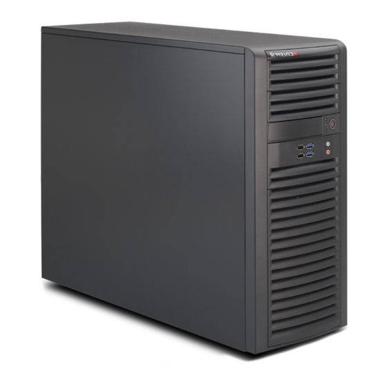
Chapter 1: Workstation Overview Chassis Features The 5037A-i2-MA015 is a workstation with Whisper Quiet operation. The following is a general outline of its main features. See Figure 1-3 for a front view of the chassis. System Power The 5037A-i2-MA015 features a single 900W Gold Level multi-outlet power supply with PMBus, ideal for use in a workstation environment. - Page 10 5037A-i2-MA015 User's Manual Figure 1-1. Control Panel Header Pins Ground Power On LED LED VCC HDD LED LED VCC NIC1 LED LED VCC NIC2 LED LED VCC OH/Fan Fail LED LED VCC LED VCC Power Fail LED Ground...
- Page 11 Chapter 1: Workstation Overview Figure 1-3. Front View of Workstation LAN Activity LED Main Power USB Ports (2x USB 3.0 and 2x USB 2.0) HDD Activity LED Overheat/Fan Fail LED Audio Microphone Eight SATA Drive Bays (inside chassis)
-
Page 12: Contacting Supermicro
5037A-i2-MA015 User's Manual Contacting Supermicro Headquarters Address: Super Micro Computer, Inc. 980 Rock Ave. San Jose, CA 95131 U.S.A. Tel: +1 (408) 503-8000 Fax: +1 (408) 503-8008 Email: marketing@supermicro.com (General Information) support@supermicro.com (Technical Support) Web Site: www.supermicro.com Europe Address: Super Micro Computer B.V. -
Page 13: Chapter 2 Workstation Setup
Chapter 2: Workstation Setup Chapter 2 Workstation Setup Unpacking the System You should inspect the box the system was shipped in and note if it was damaged in any way. If the system itself shows damage you should fi le a damage claim with the carrier who delivered it. -
Page 14: Motherboard Layout
5037A-i2-MA015 User's Manual Motherboard Layout This section provides details on the motherboard and jumper settings that may be useful when setting up the system. Figure 2-1. Layout FAN 5 FAN 5 USB 6/7 USB 6/7 USB3.0 0/1 USB3.0 0/1... - Page 15 Chapter 2: Workstation Setup Motherboard Headers/Connectors Connector Description AUDIO FP Front Panel Audio Header COM1, COM2 COM1 & COM2 Serial Port Headers USB 8/9, USB 10/11, USB 12/13 USB 2.0 Headers for front panel access JUSB2/3 (USB 3.0) USB 3.0 Header for USB 2/3 USB 0/1, USB 2/3, USB 4/5, USB 6/7 Back Panel USB 2.0 Ports USB 3.0 0/1...
-
Page 16: Jumper Settings
5037A-i2-MA015 User's Manual Jumper Settings Explanation of Jumpers To modify the operation of the mother- board, jumpers can be used to choose Connector between optional settings. Jumpers Pins create shorts between two pins to change the function of the connector. - Page 17 Chapter 2: Workstation Setup LAN Port Enable/Disable (JPL2) GLAN Enable Jumper Settings Jumper JPL2 enables or disables LAN Pin# Defi nition Port 2 on the motherboard. See the table Enabled on the right for jumper settings. The de- Disabled fault setting is Enabled. Watch Dog Reset (JWD1) Watch Dog (JWD1) is a system monitor that can reboot the system when a soft-...
- Page 18 5037A-i2-MA015 User's Manual ME Recovery (JPME1) ME Recovery ME Recovery (JPME1) is used to enable Jumper Settings or disable the ME Recovery feature of the Jumper Setting Defi nition motherboard. Place the jumper on pins Normal 1-2 for normal operation. Jump pins 2-3 to...
-
Page 19: Onboard Indicators
Chapter 2: Workstation Setup Onboard Indicators LAN Port LEDs The LAN ports are located on the I/O panel. Link LEDs (Green/Amber/Off) Each Ethernet LAN port has two LEDs. LED Color Defi nition The yellow LED indicates activity, while No Connection or 10 Mbps the Link LED may be green, amber or off Green 100 Mbps... - Page 20 5037A-i2-MA015 User's Manual Notes...
-
Page 21: Chapter 3 Component Installation
4. Disconnect the cord from the power strip or wall outlet. Accessing the System The 5037A-i2-MA015 features two removable side covers, allowing easy access to the chassis interior. Removing the Side Covers 1. Disconnect the system from any power souce. -
Page 22: Adding Pci Add-On Cards
Figure 3-1. Removing the Side Covers Adding PCI Add-On Cards The 5037A-i2-MA015 can accommodate standard size add-on cards populated in all slots. Installing an Add-on Card 1. Begin by removing power from the system as described on page 3-1. -
Page 23: Installing A Cpu And Heat Sink
Chapter 3: Component Installation Installing a CPU and Heat Sink Caution: When handling the processor package, avoid placing direct pressure on the label area of the fan. Preparation 1. Begin by removing power from the system as described on page 3-1. Always connect the power cord last and always remove it before adding, removing or changing the CPU. - Page 24 5037A-i2-MA015 User's Manual 3. With the lever labeled 'Close 1st' fully retracted, gently push down on the 'Open 1st' lever to open the load plate. Lift the load plate to open it completely. Gently push 4. Using your thumb and the index...
- Page 25 Chapter 3: Component Installation Caution: CPUs only install to the socket in one direction. Make sure that the CPU is properly inserted into the socket before closing the load plate. If it doesn't close properly, do not force it as it may damage your CPU. Instead, open the load plate again and double-check that the CPU is aligned properly.
-
Page 26: Installing A Cpu Heat Sink
5037A-i2-MA015 User's Manual Installing a CPU Heat Sink 1. Do not apply any thermal grease to the heat sink or the CPU die; the required amount has already been applied. 2. Place the heat sink on top of the CPU so that the four mounting holes are aligned with those on the motherboard and the heat sink bracket underneath. -
Page 27: Removing The Heat Sink
Chapter 3: Component Installation Removing the Heat Sink Preparation 1. Begin by removing power from the system as described on page 3-1. 2. Remove the power cord from the system before removing the heatsink. 3. Unscrew the heat sink screws from the motherboard in the sequence as shown in the illustration below. -
Page 28: Installing Memory Modules
5037A-i2-MA015 User's Manual Installing Memory Modules Check the Supermicro Web site for recommended memory modules. Caution: Exercise extreme care when installing or removing DIMM modules to prevent any possible damage. Preparation 1. Begin by removing power from the system as described on page 3-1. -
Page 29: Memory Support
Chapter 3: Component Installation Memory Support The 5037A-i2-MA015 supports up to 256 GB of 1600/1066/1333/1600 MHz ECC/ Non-ECC DDR3 DIMMS in eight memory slots. For the latest memory updates, please refer to the product page on the Supermicro Web site. -
Page 30: System Fans
5037A-i2-MA015 User's Manual System Fans One 12-cm chassis cooling fan provides air intake while another 12-cm exhaust fan expels hot air from the chassis. Both are low-noise fans that result in "Whisper-Quiet" operation (~28 dB). The fans should be connected to headers on the motherboard (see Chapter 5). -
Page 31: Hard Drive Installation
Figure 5-5. Removing a Chassis Fan Hard Drive Installation A total of eight SAS or SATA drives may be housed in the 5037A-i2-MA015. The drive IDs are preconfi gured as 0 through 7 in order from bottom to top. Remove the side panel of the chassis to access these drives as described previously in this chapter. - Page 32 5037A-i2-MA015 User's Manual Figure 3-6. Removing the Drive Carrier Release Tab (A) HDD Cage (B) Removing a Hard Drive 1. Press the release tab on the side of the hard drive carrier which is to be removed from the hard drive cage.
- Page 33 Chapter 3: Component Installation Figure 3-7. Removing the Hard Drive Carrier from the Hard Drive Cage Release Tabs Figure 3-8. Removing a Hard Drive from the Drive Carrier 3-13...
- Page 34 5037A-i2-MA015 User's Manual Figure 3-9. Installing a Hard Drive Carrier into the Hard Drive Cage Optional Screw 1. Insert the new hard drive into the hard drive carrier. 2. Insert the hard drive carrier into the hard drive cage, sliding it towards the back of the the hard drive cage until it clicks into a locked position.
-
Page 35: Optional 2.5" Hard Drives
Optional 2.5" Hard Drives Figure 3-10. Removing 2.5" Hard Drives Thumbscrew The 5037A-i2-MA015 must be powered-down before hard drives can be removed from the hard drive carriers. Removing and Installing 2.5" Hard Drives 1. Disconnect the chassis from any power source. -
Page 36: Power Supply
5037A-i2-MA015 User's Manual Power Supply The 5037A-i2-MA015 includes a 900 Watt power supply. In the unlikely event that it becomes necessary to replace the power supply, follow the instructions below. Figure 3-11. Removing the Power Supply Power Supply Preparation Begin by removing power from the system as described on page 3-1. -
Page 37: Motherboard Battery
Chapter 3: Component Installation Motherboard Battery CAUTION: There is a danger of explosion if the onboard battery is installed upside down, which will reverse its polarities (see Figure 3-12). This battery must be re- placed only with the same or an equivalent type recommended by the manufacturer (CR2032). - Page 38 5037A-i2-MA015 User's Manual Notes 3-18...
-
Page 39: Appendix A Software
Appendix A Software A-1 Operating System The 5037A-i2-MA015 supports the Windows 7 Professional 64-bit Operating Sys- tem. This OS has been pre-installed to the system. System Recovery Instructions This computer includes a hidden partition which contains a backup of your factory Windows installation. -
Page 40: A-2 Installing Drivers
5037A-i2-MA015 User's Manual A-2 Installing Drivers With the hardware and operating system installed, you may need to install the drivers if not done already. The drivers are available online at http://www.supermicro.com/support/resources/ Obtaining Drivers 1. Go to the Advanced Search area and select the Category (motherboards), Product Type and Model (motherboard model) from the drop-down menus. -
Page 41: A-3 Superdoctor Iii
BIOS. Any subsequent changes to these thresholds must be made within SuperDoctor, as the SuperDoctor settings override the BIOS settings. To set the BIOS temperature threshold settings again, you would fi rst need to uninstall SuperDoctor. Supero Doctor III Interface Display Screen (Health Information) -
Page 42: Superdoctor Iii
5037A-i2-MA015 User's Manual Supero Doctor III Interface Display Screen (Remote Control) Note: The SuperDoctor III program and User's Manual can be downloaded from the Supermicro Web site at http://www.supermicro.com/products/accessories/software/ SuperDoctorIII.cfm. For Linux, we recommend using SuperDoctor II. A-4 BIOS The AMI ROM BIOS is stored in a Flash EEPROM and can be easily updated. -
Page 43: How To Change The Confi Guration Data
Appendix A: Software confi gured by the user. The right frame displays the key legend. Above the key legend is an area reserved for a description of the highlighted option. When an option is selected in the left frame, it is highlighted in white. Often a text message will accompany it. - Page 44 5037A-i2-MA015 User's Manual Notes...
-
Page 45: Appendix B Bios Beep Codes
Appendix B: BIOS Beep Codes Appendix B BIOS Beep Codes During the POST (Power-On Self-Test) routines, which are performed each time the system is powered on, errors may occur. Non-fatal errors are those which, in most cases, allow the system to continue with bootup. - Page 46 5037A-i2-MA015 User's Manual Notes...
-
Page 47: Appendix C System Specifi Cations
Appendix C: System Specifi cations Appendix C System Specifi cations Processors Intel Xeon E5-2600 / 1600 Series Processor Socket R (LGA 2011). Note: Please refer to our web site for a complete listing of supported processors. Chipset Intel C602 BIOS 32 Mb SPI AMI BIOS®... - Page 48 5037A-i2-MA015 User's Manual Chassis SC732D4-903B Form Factor: Mid-tower Dimensions (WxHxD) 7.6 x 16.7 x 20.68 in. (193 x 424 x 525.3 mm) Weight Gross (Bare Bone): 39 lbs. (17.7 kg.) System Cooling One 12-cm low-noise exhaust fan One active CPU heatsink (optional)
- Page 49 Appendix C: System Specifi cations Notes...
- Page 50 5037A-i2-MA015 User's Manual (continued from front) The products sold by Supermicro are not intended for and will not be used in life support systems, medical equipment, nuclear facilities or systems, aircraft, aircraft devices, aircraft/emergency com- munication devices or other critical systems whose failure to perform be reasonably expected to result in signifi...
Need help?
Do you have a question about the SuperWorkstation 5037A-i2-MA015 and is the answer not in the manual?
Questions and answers