Table of Contents
Advertisement
Quick Links
Проконсультироваться и купить данное оборудование вы можете в компании «АНД-Системс»
адрес: 125480, г.Москва, ул.Туристская, д.33/1; site: https://andpro.ru тел: +7 (495) 545-4870 email: info@andpro.ru
При обращении используйте промокод AND-PDF и получите скидку.
S
UPER
®
S
W
uper
orkstation
5038A-IL
USER'S MANUAL
1.0
Advertisement
Table of Contents

Subscribe to Our Youtube Channel
Related Manuals for Supero SuperWorkstation 5038A-IL


Summary of Contents for Supero SuperWorkstation 5038A-IL
- Page 1 Проконсультироваться и купить данное оборудование вы можете в компании «АНД-Системс» адрес: 125480, г.Москва, ул.Туристская, д.33/1; site: https://andpro.ru тел: +7 (495) 545-4870 email: info@andpro.ru При обращении используйте промокод AND-PDF и получите скидку. UPER ® uper orkstation 5038A-IL USER’S MANUAL...
- Page 2 The information in this User’s Manual has been carefully reviewed and is believed to be accurate. The vendor assumes no responsibility for any inaccuracies that may be contained in this document, makes no commitment to update or to keep current the information in this manual, or to notify any person or organization of the updates.
-
Page 3: About This Manual
About This Manual This manual is written for professional system integrators and PC technicians. It provides information for the installation and use of the SuperWorkstation 5038A-IL. Installation and maintenance should be performed by experienced technicians only. The SuperWorkstation 5038A-IL is a high-end system based on the SC732D4F- 500B tower chassis and the X10SAE serverboard. - Page 4 uper orkstation 5038A-IL User's Manual Chapter 5: Advanced Serverboard Setup Chapter 5 provides detailed information on the X10SAE serverboard, including the locations and functions of connections, headers and jumpers. Refer to this chapter when adding or removing processors or main memory and when reconfi guring the serverboard.
- Page 5 Preface Notes...
-
Page 6: Table Of Contents
uper orkstation 5038A-IL User's Manual Table of Contents Chapter 1 Introduction Overview ......................1-1 Serverboard Features ..................1-2 Processors ...................... 1-2 Memory ......................1-2 SATA ........................ 1-2 PCI Expansion Slots ..................1-2 Onboard Controllers/Ports ................1-2 Chassis Features .................... 1-3 System Power .................... - Page 7 Table of Contents Circuit Breaker ....................4-5 Power Disconnection Warning ................ 4-6 Equipment Installation ..................4-8 Restricted Area ....................4-9 Battery Handling .................... 4-10 Redundant Power Supplies ................4-12 Backplane Voltage ..................4-13 Comply with Local and National Electrical Codes ........4-14 Product Disposal ...................
- Page 8 uper orkstation 5038A-IL User's Manual Chapter 6 Advanced Chassis Setup Static-Sensitive Devices .................. 6-1 Precautions ..................... 6-1 Unpacking ....................... 6-1 Accessing the Inside of the System..............6-2 Rotating the Hard Drive Cage................. 6-3 Removing and Installing 3.5" Hard Drives ............6-4 Removing and Installing 2.5"...
-
Page 9: Chapter 1 Introduction
SC732D4F-500B tower chassis and the X10SAE single Intel® Xeon® processor serverboard. Please refer to our web site for information on operating systems that have been certifi ed for use with the SuperWorkstation 5038A-IL (www.supermicro. com). In addition to the serverboard and chassis, various hardware components have been included with the SuperWorkstation 5038A-IL, as listed below: •... -
Page 10: Serverboard Features
5038A-IL User's Manual Serverboard Features At the heart of the SuperWorkstation 5038A-IL lies the X10SAE, a single processor serverboard based on the Intel® C226 chipset. Below are the main features of the X10SAE. (See Figure 1-1 for a block diagram of the chipset). -
Page 11: Chassis Features
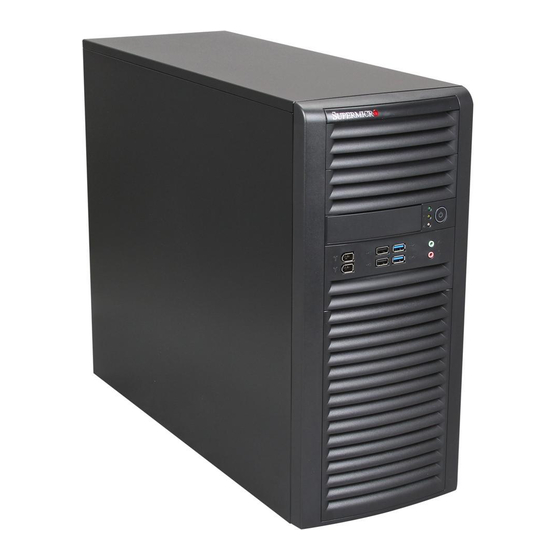
The SC732D4F-500B chassis was designed to support eight SATA hard drives. Front Control Panel The control panel on the SuperWorkstation 5038A-IL includes system monitoring LEDs and a main power button. In addition, two IEEE 1394a ports, two USB 2.0 ports, two USB 3.0 ports, one audio port and one microphone port are included on the control panel. -
Page 12: System Block Diagram
uper orkstation 5038A-IL User's Manual Figure 1-1. Intel C226 Chipset: System Block Diagram Note: This is a general block diagram. Please see Chapter 5 for details. PCIe3.0_x16 PCIe x16 SLOT #6 VRD12.5 8.0GT/s SVID PCIe3.0_x8 VRM 12.5 8.0GT/s INTEL LGA1150 ASMedia Switch PCIe3.0_x8 PCIe3.0_x8 ASM1480... -
Page 13: Contacting Supermicro
Chapter 1: Introduction Contacting Supermicro Headquarters Address: Super Micro Computer, Inc. 980 Rock Ave. San Jose, CA 95131 U.S.A. Tel: +1 (408) 503-8000 Fax: +1 (408) 503-8008 Email: marketing@supermicro.com (General Information) support@supermicro.com (Technical Support) Web Site: www.supermicro.com Europe Address: Super Micro Computer B.V. Het Sterrenbeeld 28, 5215 ML 's-Hertogenbosch, The Netherlands Tel:... - Page 14 uper orkstation 5038A-IL User's Manual Notes...
-
Page 15: Chapter 2 Installation
Installation Overview This chapter provides a quick setup checklist to get your SuperWorkstation 5038A-IL up and running. Following these steps in the order given should enable you to have the system operational within a minimum amount of time. This quick setup assumes that your system has come to you with the processor and memory preinstalled. -
Page 16: Accessing The Inside Of The System
uper orkstation 5038A-IL User's Manual Accessing the Inside of the System You may need to access the system periodically to perform maintenance or install components such as hard drives. The SC732 features two removable side covers, allowing easy access to the chassis interior. Removing the Side Covers 1. -
Page 17: Chapter 3 System Interface
Chapter 3: System Interface Chapter 3 System Interface Overview The control panel on the 5038A-IL has several LEDs and a power button. These LEDs keep you constantly informed of the overall status of the system and the activity and health of specifi c components. Control Panel Button A single push-button is located on the front of the chassis. -
Page 18: Control Panel Leds
uper orkstation 5038A-IL User's Manual NIC LED HDD LED OH LED Power Button Audio 2x 1394a 2x USB 2.0 2x USB 3.0 Control Panel LEDs The control panel located on the front of the SC732 chassis has three LEDs. These LEDs provide you with critical information related to different parts of the system. -
Page 19: Overheat/Fan Fail
Chapter 3: System Interface Overheat/Fan Fail When this LED fl ashes, it indicates a chassis fan failure. When on continuously it indicates an overheat condition, which may be caused by cables obstructing the airfl ow in the system or the ambient room temperature being too warm. Check the routing of the cables and make sure all fans are present and operating normally. - Page 20 uper orkstation 5038A-IL User's Manual Notes...
-
Page 21: Chapter 4 Standardized Warning Statements For Ac Systems
Chapter 4: Warning Statements for AC Systems Chapter 4 Standardized Warning Statements for AC Systems About Standardized Warning Statements The following statements are industry standard warnings, provided to warn the user of situations which have the potential for bodily injury. Should you have questions or experience difficulty, contact Supermicro's Technical Support department for assistance. - Page 22 uper orkstation 5038A-IL User's Manual Warnung WICHTIGE SICHERHEITSHINWEISE Dieses Warnsymbol bedeutet Gefahr. Sie befi nden sich in einer Situation, die zu Verletzungen führen kann. Machen Sie sich vor der Arbeit mit Geräten mit den Gefahren elektrischer Schaltungen und den üblichen Verfahren zur Vorbeugung vor Unfällen vertraut.
- Page 23 Warning Statements for AC Systems ﺟﺴﺪﻳﺔ ﺍﺻﺎﺑﺔ ﺗﺘﺴﺒﺐ ﻓﻲ ﺣﺎﻟﺔ ﻳﻤﻜﻦ ﺃﻥ ﺍﻧﻚ ﻓﻲ ﺧﻄﺮ ﻳﻌﻨﻲ ﻫﺬﺍ ﺍﻟﺮﻣﺰ !ﺗﺤﺬﻳﺮ ﺍﻟﺪﻭﺍﺋﺮ ﺑﺎﻟﻤﺨﺎﻁﺮ ﺍﻟﻨﺎﺟﻤﺔ ﻋﻦ ﻦ ﻋﻠﻰ ﻋﻠﻢ ، ﻛ ﻣﻌﺪﺍﺕ ﺗﻌﻤﻞ ﻋﻠﻰ ﺃﻱ ﻗﺒﻞ ﺃﻥ ﺍﻟﻜﻬﺮﺑﺎﺋﻴﺔ ﺣﻮﺍﺩﺙ ﺃﻱ ﻭﻗﻮﻉ ﻤﻨﻊ ﻟ ﺍﻟﻮﻗﺎﺋﻴﺔ...
-
Page 24: Installation Instructions
uper orkstation 5038A-IL User's Manual Installation Instructions Warning! Read the installation instructions before connecting the system to the power source. 設置手順書 システムを電源に接続する前に、 設置手順書をお読み下さい。 警告 将此系统连接电源前,请先阅读安装说明。 警告 將系統與電源連接前,請先閱讀安裝說明。 Warnung Vor dem Anschließen des Systems an die Stromquelle die Installationsanweisungen lesen. ¡Advertencia! Lea las instrucciones de instalación antes de conectar el sistema a la red de alimentación. -
Page 25: Circuit Breaker
Chapter 4: Warning Statements for AC Systems Circuit Breaker Warning! This product relies on the building's installation for short-circuit (overcurrent) protection. Ensure that the protective device is rated not greater than: 250 V, 20 A. サーキッ ト ・ ブレーカー この製品は、 短絡 (過電流) 保護装置がある建物での設置を前提としています。 保護装置の定格が250 V、... -
Page 26: Power Disconnection Warning
uper orkstation 5038A-IL User's Manual 경고! 이 제품은 전원의 단락(과전류)방지에 대해서 전적으로 건물의 관련 설비에 의존합니다. 보호장치의 정격이 반드시 250V(볼트), 20A(암페어)를 초과하지 않도록 해야 합니다. Waarschuwing Dit product is afhankelijk van de kortsluitbeveiliging (overspanning) van uw electrische installatie. Controleer of het beveiligde aparaat niet groter gedimensioneerd is dan 220V, 20A. - Page 27 Chapter 4: Warning Statements for AC Systems ¡Advertencia! El sistema debe ser disconnected de todas las fuentes de energía y del cable eléctrico quitado de los módulos de fuente de alimentación antes de tener acceso el interior del chasis para instalar o para quitar componentes de sistema. Attention Le système doit être débranché...
-
Page 28: Equipment Installation
uper orkstation 5038A-IL User's Manual Equipment Installation Warning! Only trained and qualifi ed personnel should be allowed to install, replace, or service this equipment. 機器の設置 トレーニングを受け認定された人だけがこの装置の設置、 交換、 またはサービスを許可 されています。 警告 只有经过培训且具有资格的人员才能进行此设备的安装、更换和维修。 警告 只有經過受訓且具資格人員才可安裝、更換與維修此設備。 Warnung Das Installieren, Ersetzen oder Bedienen dieser Ausrüstung sollte nur geschultem, qualifi... -
Page 29: Restricted Area
Chapter 4: Warning Statements for AC Systems Waarschuwing Deze apparatuur mag alleen worden geïnstalleerd, vervangen of hersteld door geschoold en gekwalifi ceerd personeel. Restricted Area Warning! This unit is intended for installation in restricted access areas. A restricted access area can be accessed only through the use of a special tool, lock and key, or other means of security. -
Page 30: Battery Handling
uper orkstation 5038A-IL User's Manual אזור עם גישה מוגבלת !אזהרה יש להתקין את היחידה באזורים שיש בהם הגבלת גישה. הגישה ניתנת בעזרת .('כלי אבטחה בלבד )מפתח, מנעול וכד ﻣﺤﻈﻮﺭﺓ ﻣﻨﺎﻁﻖ ﻟﺘﺮﻛﻴﺒﻬﺎ ﻓﻲ ﻫﺬﻩ ﺍﻟﻮﺣﺪﺓ ﺗﺨﺼﻴﺺ ﺗﻢ ،ﺃﺩﺍﺓ ﺧﺎﺻﺔ ﻣﻦ ﺧﻼﻝ ﺍﺳﺘﺨﺪﺍﻡ ﻓﻘﻂ... - Page 31 Chapter 4: Warning Statements for AC Systems Warnung Bei Einsetzen einer falschen Batterie besteht Explosionsgefahr. Ersetzen Sie die Batterie nur durch den gleichen oder vom Hersteller empfohlenen Batterietyp. Entsorgen Sie die benutzten Batterien nach den Anweisungen des Herstellers. Attention Danger d'explosion si la pile n'est pas remplacée correctement. Ne la remplacer que par une pile de type semblable ou équivalent, recommandée par le fabricant.
-
Page 32: Redundant Power Supplies
uper orkstation 5038A-IL User's Manual Redundant Power Supplies Warning! This unit might have more than one power supply connection. All connections must be removed to de-energize the unit. 冗長電源装置 このユニッ トは複数の電源装置が接続されている場合があります。 ユニッ トの電源を切るためには、 すべての接続を取り外さなければなりません。 警告 此部件连接的电源可能不止一个,必须将所有电源断开才能停止给该部件供电。 警告 此裝置連接的電源可能不只一個,必須切斷所有電源才能停止對該裝置的供電。 Warnung Dieses Gerät kann mehr als eine Stromzufuhr haben. Um sicherzustellen, dass der Einheit kein trom zugeführt wird, müssen alle Verbindungen entfernt werden. -
Page 33: Backplane Voltage
Chapter 4: Warning Statements for AC Systems ﺍﻣﺪﺍﺩ ﺍﻟﻄﺎﻗﺔ ﺑﻮﺣﺪﺍﺕ ﻋﺪﺓ ﺍﺗﺼﺎﻻﺕ ﺠﻬﺎﺯ ﺍﻟ ﻳﻜﻮﻥ ﻟﻬﺬﺍ ﻗﺪ ﺍﻟﻜﻬﺮﺑﺎء ﻋﻦ ﻮﺣﺪﺓ ﺍﻟ ﻟﻌﺰﻝ ﻛﺎﻓﺔ ﺍﻻﺗﺼﺎﻻﺕ ﻳﺠﺐ ﺇﺯﺍﻟﺔ 경고! 이 장치에는 한 개 이상의 전원 공급 단자가 연결되어 있을 수 있습니다. 이 장치에 전원을... -
Page 34: Comply With Local And National Electrical Codes
uper orkstation 5038A-IL User's Manual מתח בפנל האחורי !הרה אז קיימת סכנת מתח בפנל האחורי בזמן תפעול המערכת. יש להיזהר במהלך .העבודה ﺍﻟﻠﻮﺣﺔ ﺃﻭﺍﻟﻄﺎﻗﺔ ﺍﻟﻤﻮﺟﻮﺩﺓ ﻋﻠﻰ ﺍﻟﺘﻴﺎﺭ ﺍﻟﻜﻬﺮﺑﺎﺋﻲ ﻣﻦ ﺧﻄﺮ ﻫﻨﺎﻙ ﻫﺬﺍ ﺍﻟﺠﻬﺎﺯ ﺧﺪﻣﺔ ﻛﻦ ﺣﺬﺭﺍ ﻋﻨﺪ ﻳﻌﻤﻞ ﺍﻟﻨﻈﺎﻡ ﻋﻨﺪﻣﺎ ﻳﻜﻮﻥ 경고! 시스템이... -
Page 35: Product Disposal
Chapter 4: Warning Statements for AC Systems Attention L'équipement doit être installé conformément aux normes électriques nationales et locales. תיאום חוקי החשמל הארצי !אזהרה הציוד חייבת להיות תואמת לחוקי החשמל המקומיים והארציים התקנת ﺍﻟﻤﺘﻌﻠﻘﺔ ﺍﻟﻤﺤﻠﻴﺔ ﻭﺍﻟﻮﻁﻨﻴﺔ ﻘﻮﺍﻧﻴﻦ ﻳﺠﺐ ﺃﻥ ﻳﻤﺘﺜﻞ ﻟﻠ ﺍﻟﻜﻬﺮﺑﺎﺋﻴﺔ... -
Page 36: Hot Swap Fan Warning
uper orkstation 5038A-IL User's Manual ¡Advertencia! Al deshacerse por completo de este producto debe seguir todas las leyes y reglamentos nacionales. Attention La mise au rebut ou le recyclage de ce produit sont généralement soumis à des lois et/ou directives de respect de l'environnement. Renseignez-vous auprès de l'organisme compétent. - Page 37 Chapter 4: Warning Statements for AC Systems 警告 當您從機架移除風扇裝置,風扇可能仍在轉動。小心不要將手指、螺絲起子和其他 物品太靠近風扇。 Warnung Die Lüfter drehen sich u. U. noch, wenn die Lüfterbaugruppe aus dem Chassis genommen wird. Halten Sie Finger, Schraubendreher und andere Gegenstände von den Öffnungen des Lüftergehäuses entfernt. ¡Advertencia! Los ventiladores podran dar vuelta cuando usted quite ell montaje del ventilador del chasis.
-
Page 38: Power Cable And Ac Adapter
uper orkstation 5038A-IL User's Manual Power Cable and AC Adapter Warning! When installing the product, use the provided or designated connection cables, power cables and AC adaptors. Using any other cables and adaptors could cause a malfunction or a fi re. Electrical Appliance and Material Safety Law prohibits the use of UL or CSA -certifi... - Page 39 Chapter 4: Warning Statements for AC Systems Attention Lors de l'installation du produit, utilisez les bables de connection fournis ou désigné. L'utilisation d'autres cables et adaptateurs peut provoquer un dysfonctionnement ou un incendie. Appareils électroménagers et de loi sur la sécurité Matériel interdit l'utilisation de UL ou CSA câbles certifi...
- Page 40 uper orkstation 5038A-IL User's Manual Notes 4-20...
-
Page 41: Chapter 5 Advanced Serverboard Setup
Chapter 5: Advanced Serverboard Setup Chapter 5 Advanced Serverboard Setup This chapter covers the steps required to connect the data and power cables and install add-on cards. All serverboard jumpers and connections are also described. A layout and quick reference chart are included in this chapter for your reference. Handling the Serverboard Electrostatic discharge (ESD) can damage electronic com ponents. -
Page 42: Connecting Cables
uper orkstation 5038A-IL User's Manual Connecting Cables Now that the serverboard is installed, the next step is to connect the cables to the board. These include the data (ribbon) cables for the peripherals and control panel and the power cables. Connecting Data Cables The cables used to transfer data from the peripheral devices have been carefully routed to prevent them from blocking the fl... -
Page 43: I/O Ports
Chapter 5: Advanced Serverboard Setup Figure 5-1. Control Panel Header Pins LED_Anode+ Power LED LED_Anode+ HDD LED LED_Anode+ NIC1 LED LED_Anode+ NIC2 LED OH/Fan Fail LED LED_Anode+ Reset Reset Button Ground Power Button Ground I/O Ports The I/O ports are color coded in conformance with the PC 99 specifi cation. See Figure 5-2 below for the colors and locations of the various I/O ports. -
Page 44: Processor And Heatsink Installation
uper orkstation 5038A-IL User's Manual Processor and Heatsink Installation Warning: When handling the processor package, avoid placing direct pressure on the label area of the fan. Notes: • Always connect the power cord last and always remove it before adding, re- moving or changing any hardware components. - Page 45 Chapter 5: Advanced Serverboard Setup 5. Align the CPU key, which is a semi- circle cutout, against the socket CPU Key key, which is the notch below the gold color dot on the side of the socket. 6. Align pin 1 of the CPU against pin 1 of the CPU socket.
-
Page 46: Installing The Heatsink
uper orkstation 5038A-IL User's Manual Installing the Heatsink 1. Locate the CPU Fan power connec- tor on the motherboard. 2. Position the heatsink so that the heatsink fan wires are closest to the CPU fan power connector and are not interfered with other compo- nents. -
Page 47: Removing The Heatsink
Chapter 5: Advanced Serverboard Setup 8. Repeat Step 7 to insert all four heatsink fasteners into the mounting holes. 9. Once all four fasteners are securely inserted into the mounting holes, and the heatsink is properly installed on the motherboard, connect the heatsink fan wires to the CPU Fan connector. -
Page 48: Installing Memory Modules
uper orkstation 5038A-IL User's Manual Installing Memory Modules Note: Check the Supermicro web site for recommended memory modules. CAUTION Exercise extreme care when installing or removing DIMM modules to prevent any possible damage. Installing & Removing DIMMs 1. Insert the desired number of DIMMs into the memory slots, starting with DIMMA1. -
Page 49: Memory Population Guidelines
Chapter 5: Advanced Serverboard Setup Memory Support The X10SAE supports up to 32 GB of Unbuffered ECC/Non-ECC DDR3-1600/1066 MHz memory in four DIMM slots. For the latest memory updates, please refer to our website. For memory to work properly, follow the tables below for the correct order of populat- ing the DIMM slots. - Page 50 uper orkstation 5038A-IL User's Manual • For Microsoft Windows users: Microsoft implemented a design change in Windows XP with Service Pack 2 (SP2) and Windows Vista. This change is specifi c to the behavior of Physical Address Extension (PAE) mode, which improves driver compatibility.
-
Page 51: Adding Pci Add-On Cards
Chapter 5: Advanced Serverboard Setup Adding PCI Add-On Cards The 5038A-IL can accommodate standard size add-on cards populated in all slots on the X10SAE serverboard. Installing an Add-on Card 1. Begin by removing the PCI slot shield for the slot you wish to populate. 2. -
Page 52: Serverboard Details
uper orkstation 5038A-IL User's Manual Serverboard Details Figure 5-4. X10SAE Layout USB 10/11 USB 2/3 USB 0/1 JPL2 JPAC1 HDMI/DP JSPDIF_OUT HD AUDIO KB/MOUSE LAN 2 LAN 1 JHD_AC1 COM4 FAN5 JPW2 JPL1 JI2C1 JI2C2 X10SAE Rev. 1.01 LV33 JPME2 Battery DIMMA1 DIMMA2... - Page 53 Chapter 5: Advanced Serverboard Setup Connector Description 1394_1/2 1394 Connectors 1/2 Audio FP Front Panel Audio Header HD AUDIO High-Defi nition Audio Connectors (on I/O back panel) COM1/COM2 COM1/COM2 Port Headers Fan1~Fan5 System/CPU Fan Headers (Fan1: CPU Fan) HDMI/DP Backplane HDMI/DP Audio Port Speaker/buzzer Front Panel Control Header Chassis Intrusion Header...
-
Page 54: Connector Defi Nitions
uper orkstation 5038A-IL User's Manual Connector Defi nitions Main ATX Power Connector Pin Defi nitions Pin# Defi nition Pin # Defi nition Main ATX Power Supply +3.3V +3.3V Connector -12V +3.3V A 24-pin main power supply connec- tor (JPW1) and an 8-pin CPU power PS_ON connectors (JPW2) are located on the serverboard. - Page 55 Chapter 5: Advanced Serverboard Setup Overheat/Fan Fail LED (OH) OH/Fan Fail Indicator OH/Fan Fail LED Status Pin Defi nitions (JF1) Connect an LED to pins 7 and 8 of State Defi nition Pin# Defi nition JF1 to provide advanced warning of Normal Vcc/Blue UID chassis overheating or fan failure.
- Page 56 uper orkstation 5038A-IL User's Manual Fan Headers Fan Header The X10SAE has fi ve fan headers Pin Defi nitions (Fan 1-5), all of which are 4-pin fans. Pin# Defi nition Although pins 1-3 of the fan headers Ground (Black) are backward compatible with the tra- 2.5A/+12V (Red) ditional 3-pin fans, we recommend the...
- Page 57 Chapter 5: Advanced Serverboard Setup SGPIO Headers SGPIO Header Pin Defi nitions Two SGPIO (Serial General Purpose Pin# Defi nition Defi nition Input/Output) headers are designated T-SGPIO1 and SGPIO2. These head- Ground Data ers are used to communicate with Load Ground the system's enclosure management Clock...
- Page 58 uper orkstation 5038A-IL User's Manual Universal Serial Bus (USB) Four Universal Serial Bus 2.0 ports (0/1, 2/3) and two USB 3.0 ports (10/11) are located on the I/O back panel. In addition, three USB 2.0 headers (six USB 2.0 connections: 4/5, 6/7, 8/9), and two USB 3.0 headers (four USB 3.0 connections: 12/13, 14/15) are also located on the motherboard to provide front chassis access using USB cables (not included).
- Page 59 Chapter 5: Advanced Serverboard Setup DOM PWR Connector (JSD1) DOM PWR The Disk-On-Module (DOM) power Pin Defi nitions connector, located at JSD1, provides Pin# Defi nition 5V (Gen1/Gen) power to a solid state DOM storage device connected to one Ground of the SATA ports.
- Page 60 uper orkstation 5038A-IL User's Manual 1394_1 Pin Defi nitions Pin# Defi nition Pin# Defi nition PTPA0+ PTPA0- IEEE 1394_1/1394_2 Connectors 1394_1 and 1394_2 provide IEEE PTPB0+ PTPB0- 1394 connections on the mother- PWR 1394a 1394a board. Connect IEEE 1394 cables to Shield the connectors for IEEE 1394 sup- port.
-
Page 61: Jumper Settings
Chapter 5: Advanced Serverboard Setup Jumper Settings Explanation of Jumpers To modify the operation of the serverboard, jumpers can be used Connector to choose between optional settings. Pins Jumpers create shorts between two pins to change the function of the con- nector. - Page 62 uper orkstation 5038A-IL User's Manual LAN1/LAN2 Enable/Disable GLAN Jumpers JPL1/JPL2 enable or disable Jumper Settings LAN ports 1/2 on the motherboard. Jumper Setting Defi nition See the table on the right for jumper Enabled (default) settings. The default setting is en- Disabled abled.
- Page 63 Chapter 5: Advanced Serverboard Setup Management Engine (ME) Recovery Use jumper JPME1 to select ME Firmware Recovery mode, which will ME Recovery limit resource allocation for essential Jumper Settings system operation only in order to Jumper Setting Defi nition maintain normal power operation and Normal (Default) management.
-
Page 64: 5-10 Onboard Indicators
uper orkstation 5038A-IL User's Manual 5-10 Onboard Indicators LAN1/2 LEDs LAN1/2 LED The Ethernet ports on the I/O back- (Connection Speed Indicator) plane each have two LEDs. On each LED Color Defi nition port, one LED indicates activity while No Connection, 10 or 100 Mb/s the other LED may be green, amber Amber 1 Gb/s... -
Page 65: 5-12 Installing Software
Chapter 5: Advanced Serverboard Setup 5-12 Installing Software The Supermicro ftp site contains drivers and utilities for your system at ftp://ftp. supermicro.com. Some of these must be installed, such as the chipset driver. After accessing the ftp site, go into the CDR_Images directory and locate the ISO fi... -
Page 66: Superdoctor Iii
uper orkstation 5038A-IL User's Manual SuperDoctor III The SuperDoctor® III program is a web-based management tool that supports remote management capability. It includes Remote and Local Management tools. The local management is called SD III Client. The SuperDoctor III program allows you to monitor the environment and operations of your system. -
Page 67: 5-13 Onboard Battery
Chapter 5: Advanced Serverboard Setup Figure 5-7. SuperDoctor III Interface Display Screen (Remote Control) Note: The SuperDoctor III program and User’s Manual can be downloaded from the Supermicro web site at http://www.supermicro.com/products/accessories/soft- ware/SuperDoctorIII.cfm. For Linux, we recommend that you use the SuperDoctor II application instead. - Page 68 uper orkstation 5038A-IL User's Manual Notes 5-28...
-
Page 69: Chapter 6 Advanced Chassis Setup
Chapter 6: Advanced Chassis Setup Chapter 6 Advanced Chassis Setup This chapter covers the steps required to install components and perform simple maintenance on the SC732D4F-500B chassis. Following the component installation steps in the order given will eliminate most common problems. If some steps are unnecessary, skip ahead to the step that follows. -
Page 70: Accessing The Inside Of The System
uper orkstation 5038A-IL User's Manual Accessing the Inside of the System Figure 6-1. Removing the Chassis Side Covers The SC732 features two removable side covers, allowing easy access to the chas- sis interior. Removing the Side Covers 1. Disconnect the chassis from any power souce. 2. -
Page 71: Rotating The Hard Drive Cage
Chapter 6: Advanced Chassis Setup Rotating the Hard Drive Cage Release Tab (A) HDD Cage (B) Figure 6-2. Rotating the Hard Drive Cage In order to access and install components in the chassis interior, it is necessary to rotate the hard drive cage (B). This will provide suffi cient room to install and confi... -
Page 72: Removing And Installing 3.5" Hard Drives
uper orkstation 5038A-IL User's Manual Removing and Installing 3.5" Hard Drives Release Tabs Figure 6-3. Removing a Hard Drive Carrier from the Hard Drive Cage The SC732 chassis must be powered-down before hard drives can be removed from the hard drive carriers. Removing and Installing 3.5"... - Page 73 Chapter 6: Advanced Chassis Setup Figure 6-4. Removing a 3.5" Hard Drive from a Hard Drive Carrier 6. If a hard drive is already present, remove it by carefully pulling the sides of the hard drive carrier outward. 7. Remove the hard drive from the hard drive carrier. Warning: Only enterprise level HDDs are recommended for use in this chassis.
- Page 74 uper orkstation 5038A-IL User's Manual Optional Screw Figure 6-5. Installing a Hard Drive Carrier into the Hard Drive Cage...
-
Page 75: Removing And Installing 2.5" Hard Drives
Chapter 6: Advanced Chassis Setup Removing and Installing 2.5" Hard Drives Adding 2.5" hard drives to the system is optional. Thumb Screw Figure 6-6. Removing a 2.5" Hard Drive The SC732 chassis must be powered-down before hard drives can be removed from the hard drive carriers. - Page 76 uper orkstation 5038A-IL User's Manual Figure 6-7. Installing 2.5" Hard Drives 5. If a hard drive is already present, remove it by carefully pulling the sides of the hard drive carrier outward. 6. Remove the hard drive from the hard drive carrier. 7.
-
Page 77: Installing A 3.5" Device
Chapter 6: Advanced Chassis Setup Installing a 3.5" Device The SC732D chassis has one 3.5" device slot, which supports an optional device, such as an all-in-one card reader. Installing a 3.5" Device 1. Remove the front bezel from the chassis by lifting it upwards from the bottom, and pulling off the front of the chassis. -
Page 78: Installing System Fans
uper orkstation 5038A-IL User's Manual Installing System Fans Figure 6-9. Installing the Rear Exhaust Fan Installing the Rear Exhaust Fan 1. Disconnect all power to the chassis. 2. Insert the four rubber pins through mounting holes in the rear of the chassis and through the mounting holes in the rear fan. - Page 79 Chapter 6: Advanced Chassis Setup Figure 6-10. Installing the Front Cooling Fan (Optional) Installing the Front Cooling Fan (Optional) 1. Disconnect all power to the chassis. 2. Insert the four rubber pins through the front fan bracket and into the mounting holes in the front fan.
-
Page 80: Installing The Front Bezel
uper orkstation 5038A-IL User's Manual Installing the Front Bezel Front Bezel Installation 1. Insert the tabs on the front bezel into the mounting holse on the front of the chassis. 2. Ensure that the cover fi ts snugly. This completes the installation of basic components in the SC732 chassis Figure 6-11. -
Page 81: Power Supply
Chapter 6: Advanced Chassis Setup Power Supply The SC732 chassis includes a 500 Watt power supply. In the event that it becomes necessary to replace the power supply, follow the instructions below. Power Supply Figure 6-12. Removing the Power Supply Changing the Power Supply 1. - Page 82 uper orkstation 5038A-IL User's Manual Notes 6-14...
-
Page 83: Chapter 7 Bios
Chapter 7: BIOS Chapter 7 BIOS Introduction This chapter describes the AMI BIOS Setup Utility for the X10SAE. The ROM BIOS is stored in a Flash EEPROM and can be easily updated. This chapter describes the basic navigation of the AMI BIOS Setup Utility setup screens. Note: For AMI BIOS Recovery, please refer to the UEFI BIOS Recovery Instructions in Appendix C. -
Page 84: How To Start The Setup Utility
uper orkstation 5038A-IL User's Manual How to Start the Setup Utility Normally, the only visible Power-On Self-Test (POST) routine is the memory test. As the memory is being tested, press the <Delete> key to enter the main menu of the AMI BIOS Setup Utility. From the main menu, you can access the other setup screens. - Page 85 Chapter 7: BIOS The following Main menu items will display: System Time/System Date Use this option to change the system date and time. Highlight System Date or System Time using the arrow keys. Enter new values through the keyboard. Press the <Tab>...
-
Page 86: Advanced Setup Confi Gurations
uper orkstation 5038A-IL User's Manual Advanced Setup Confi gurations Use the arrow keys to select Boot Setup and press <Enter> to access the submenu items: Aptio Setup Utility - Copyright (C) 2012 American Megatrends, Inc. Main Advanced Event Logs IPMI Boot Security Save &... - Page 87 Chapter 7: BIOS Wait For 'F1' If Error This feature forces the system to wait until the 'F1' key is pressed if an error oc- curs. The options are Disabled and Enabled. Interrupt 19 Capture Interrupt 19 is the software interrupt that handles the boot disk function. When this item is set to Enabled, the ROM BIOS of the host adaptors will "capture"...
- Page 88 uper orkstation 5038A-IL User's Manual CPU Confi guration The following CPU information will be displayed: • Type of CPU • CPU Signature • Microcode Patch • Max (Maximum) CPU Speed • Min (Minimum) CPU Speed • CPU Speed • Processor Cores •...
- Page 89 Chapter 7: BIOS Clock Spread Spectrum If this feature is set to Enabled, the BIOS will monitor the level of Electromagnetic Interference caused by the components and will attempt to reduce the interference whenever needed. The options are Enabled and Disabled. Hyper-threading Select Enabled to support Intel Hyper-threading Technology to enhance CPU per- formance.
- Page 90 uper orkstation 5038A-IL User's Manual Note: If there is any change to this setting, you will need to reboot the system for the change to take effect. Please refer to Intel’s web site for detailed information. CPU AES Select Enable to enable Intel CPU Advanced Encryption Standard (AES) Instruc- tions for CPU to enhance data integrity.
- Page 91 Chapter 7: BIOS DDR Power Limit2 (Available when "Turbo Mode" is set to Enabled) Use this feature to set the power limit for DDR2. Use the number keys on your keyboard to enter the value. Enter 0 to use the manufacture default setting. 1-Core Ratio Limit (Available when "Turbo Mode"...
- Page 92 uper orkstation 5038A-IL User's Manual Enhanced C1E State (Available when "CPU C-States" is set to Enabled) Select Enabled to enable Enhanced C1 Power State to boost system perfor- mance. The options are Enabled and Disabled. CPU C3 Report (Available when "CPU C-States" is set to Enabled) Select Enabled to allow the BIOS to report the CPU C3 State (ACPI C2) to the operating system.
- Page 93 Chapter 7: BIOS C-State Pre-Wake Select Enabled to support C State Pre-Wake State features. The options are Enabled and Disabled Package C-State limit Select Auto for the AMI BIOS to automatically set the limit on the C-State package register. The options are C0/C1, C2, C3, C6, C7 and Auto. LakeTiny Feature Select Enabled for LakeTiny feature support for C-State confi...
- Page 94 uper orkstation 5038A-IL User's Manual Primary Display Use this feature to select the graphics device to be used as the primary display. You can select from a device installed on the CPU IGFX, CPU SLOT, or PCH SLOT. The options are Auto, CPU IGFX, CPU SLOT, and PCH SLOT. CPU SLOT (Available when Primary Display is set to Auto) Use this item to select the graphics device installed in an expansion slot sup- ported by the CPU to be used as the primary display.
- Page 95 Chapter 7: BIOS PCI-E Confi guration This item displays the information of the (graphics) device installed on a PCI-E slot. SLOT6 PCI-E 3.0 x16 SLOT6 PCI-E 3.0 x16 Gen X This feature allows the user to select PCI-E support for the device installed on SLOT6.
- Page 96 uper orkstation 5038A-IL User's Manual SLOT3 PCI-E 2.0 x 1 ASPM/SLOT5 PCI-E 2.0 x 1 ASPM/SLOT7 PCI-E 2.0 x 1 ASPM This feature confi gures the ASPM (Active State Power Management) settings for the graphics devices installed on PCI-E 2.0 SLOT3, SLOT5, or SLOT7. The options are Disabled, L0s, L1, L0sL1 and Auto.
- Page 97 Chapter 7: BIOS Memory Frequency Limiter This feature sets the limit of memory frequency for DIMM modules installed on the the motherboard. The options are Auto, 1067 (MHz), 1333 (MHz), and 1600 (MHz). Max TOLUD (Top of Low Usable DRAM) This feature sets the maximum TOLUD value, which specifi...
- Page 98 uper orkstation 5038A-IL User's Manual Port 60/64 Emulation This feature enables or disables I/O port 60h/64h emulation support. This should be enabled for complete USB keyboard legacy support for non-USB-aware op- erating systems. The options are Disabled and Enabled. XHCI Hand-Off This item is a work-around solution for operating systems that do not support XHCI (Extensible Host Controller Interface) hand-off.
- Page 99 Chapter 7: BIOS SATA Confi guration When this submenu is selected, the AMI BIOS automatically detects the presence of the SATA Devices and displays the following items: SATA Controllers This item Enables or Disables the built-in SATA controllers on the motherboard. The options are Enabled and Disabled.
- Page 100 uper orkstation 5038A-IL User's Manual If the item above - SATA Mode Select is set to IDE, the following items are displayed: Serial ATA Port 0~ Port 5 This item displays the information detected on the installed SATA drives on the particular SATA port.
- Page 101 Chapter 7: BIOS PCI Latency Timer This feature sets the latency timer of each PCI device installed on a PCI bus. Select 64 to set the PCI latency to 64 PCI bus clock cycles. The options are 32 PCI Bus Clocks, 64 PCI Bus Clocks, 96 PCI Bus Clocks, 128 PCI Bus Clocks, 160 PCI Bus Clocks, 192 PCI Bus Clocks, 224 PCI Bus Clocks and 248 PCI Bus Clocks.
-
Page 102: Acpi Settings
uper orkstation 5038A-IL User's Manual Onboard LAN1/LAN2 Option ROM Select iSCSI to use the iSCSI Option ROM to boot the computer using an iSCSI device installed in a LAN port specifi ed. Select PXE (Preboot Execution Environ- ment) to boot the computer using a PXE device installed in a LAN port specifi ed. Select Disabled to prevent system boot using a device installed in a LAN port. - Page 103 Chapter 7: BIOS TPM State Select Enabled to use TPM (Trusted Platform Module) settings for system data security. The options are Disabled and Enabled. Note: The system will reboot for the change on TPM State to take effect. Pending Operation Use this item to schedule a TPM-related operation to be performed by a security device for TPM support.
- Page 104 uper orkstation 5038A-IL User's Manual Firmware Update Confi guration ME FW Image Re-Flash Select Enable to re-fl ash the ME (Management Engine) Firmware. The options are Disable and Enable. AMT (Active Management Technology) Confi guration Intel AMT Select Enabled to use Intel Active Management Technology (AMT) to enhance system performance.
- Page 105 Chapter 7: BIOS Change (Serial Port 1 / Serial Port 2) Settings This option specifi es the base I/O port address and the Interrupt Request address of Serial Port 1 and 2. Select Auto to let the BIOS automatically assign the base I/O and IRQ address. The options for Serial Port 1 are Auto, (IO=3F8h;...
-
Page 106: Serial Port Console Redirection
uper orkstation 5038A-IL User's Manual • VDIMM • 5Vcc • PCH 1.05V • AVCC • 3.3Vcc • • VBAT Serial Port Console Redirection COM1/COM2 Use this feature to enable console redirection for COM1 and COM2 ports. The op- tions are Enabled and Disabled. The default setting is Disabled. Console Redirection Settings This feature allows the user to specify how the host computer will exchange data with the client computer, which is the remote computer used by the user. - Page 107 Chapter 7: BIOS Parity A parity bit can be sent along with regular data bits to detect data transmission errors. Select Even if the parity bit is set to 0, and the number of 1's in data bits is even. Select Odd if the parity bit is set to 0, and the number of 1's in data bits is odd.
- Page 108 uper orkstation 5038A-IL User's Manual Redirection After BIOS Post Use this feature to enable or disable legacy console redirection after BIOS POST. When set to Bootloader, legacy console redirection is disabled before booting the OS. When set to Always Enable, legacy console redirection remains enabled when booting the OS.
-
Page 109: Event Logs
Chapter 7: BIOS Flow Control This feature allows the user to set the fl ow control for Console Redirection to prevent data loss caused by buffer overfl ow. Send a "Stop" signal to stop send- ing data when the receiving buffer is full. Send a "Start" signal to start sending data when the receiving buffer is empty. - Page 110 uper orkstation 5038A-IL User's Manual When Log is Full Select Erase Immediately for all messages to be automatically erased from the event log when the event log memory is full. The options are Do Nothing and Erase Immediately. SMBIOS Event Long Standard Settings Log System Boot Event This option toggles the System Boot Event logging to enabled or disabled.
-
Page 111: Boot Settings
Chapter 7: BIOS Boot Settings Use this feature to confi gure Boot Settings: Aptio Setup Utility - Copyright (C) 2012 American Megatrends, Inc. Main Advanced Event Logs IPMI Boot Security Exit Sets the system boot order Fast Boot [Disabled] Set Boot Priority Boot Device [CD/DVD] 2nd Boot Device... - Page 112 uper orkstation 5038A-IL User's Manual Delete Boot Option Use this feature to remove a pre-defi ned boot device from which the system will boot during startup. The settings are [any pre-defi ned boot device] Delete Driver Option This feature allows the user to delete a previously defi ned boot device from which the systems boots during startup.
-
Page 113: Security Settings
Chapter 7: BIOS Security Settings This menu allows the user to confi gure the following security settings for the system. Aptio Setup Utility - Copyright (C) 2012 American Megatrends, Inc. Main Advanced Event Logs IPMI Boot Security Exit Password Description Set Administrator Password. -
Page 114: Save & Exit
uper orkstation 5038A-IL User's Manual Save & Exit Select the Exit tab from the BIOS Setup Utility screen to enter the Exit BIOS Setup screen. Aptio Setup Utility - Copyright (C) 2012 American Megatrends, Inc. Main Advanced Event Logs IPMI Boot Security Exit... - Page 115 Chapter 7: BIOS Save As User Defaults To set this feature, select Save as User Defaults from the Exit menu and press <En- ter>. This enables the user to save any changes to the BIOS setup for future use. Restore User Defaults To set this feature, select Restore User Defaults from the Exit menu and press <En- ter>.
- Page 116 uper orkstation 5038A-IL User's Manual Notes 7-34...
-
Page 117: Appendix A Bios Error Beep Codes
Appendix A: POST Error Beep Codes Appendix A BIOS Error Beep Codes During the POST (Power-On Self-Test) routines, which are performed each time the system is powered on, errors may occur. Non-fatal errors are those which, in most cases, allow the system to continue with bootup. - Page 118 uper orkstation 5038A-IL User's Manual Notes...
-
Page 119: Appendix B System Specifi Cations
Appendix B: System Specifi cations Appendix B System Specifi cations Processor One Intel E3-1200V3 series processor or 4th Generation Intel Core™ i7/i5/i3 DT processor in an LGA1150 socket Note: Please refer to our web site for a complete listing of supported processors. Chipset Intel C226 BIOS... - Page 120 uper orkstation 5038A-IL User's Manual Serverboard X10SAE Dimensions: 12" x 9.6" (305 x 244 mm) Chassis SC732D4F-500B Form Factor: mid tower Dimensions (as tower): (WxHxD) 7.6 x 16.7 x 20.7 in. (193 x 424 x 526 mm) Weight Net: 27 lbs (12.27 kg.) Gross: 32.5 lbs.
- Page 121 Appendix B: System Specifi cations Regulatory Compliance Electromagnetic Emissions: FCC Class B, EN 55022 Class B, EN 61000-3-2/-3- 3, CISPR 22 Class B Electromagnetic Immunity: EN 55024/CISPR 24, (EN 61000-4-2, EN 61000-4-3, EN 61000-4-4, EN 61000-4-5, EN 61000-4-6, EN 61000-4-8, EN 61000-4-11) Safety: CSA/EN/IEC/UL 60950-1 Compliant, UL or CSA Listed (USA and Canada), CE Marking (Europe) California Best Management Practices Regulations for Perchlorate Materials:...
- Page 122 uper orkstation 5038A-IL User's Manual (continued from front) The products sold by Supermicro are not intended for and will not be used in life support systems, medical equipment, nuclear facilities or systems, aircraft, aircraft devices, aircraft/emergency com- munication devices or other critical systems whose failure to perform be reasonably expected to result in signifi...
Need help?
Do you have a question about the SuperWorkstation 5038A-IL and is the answer not in the manual?
Questions and answers