Table of Contents
Advertisement
Quick Links
Advertisement
Table of Contents

Subscribe to Our Youtube Channel
Related Manuals for Supero AW-4021A-T2


Summary of Contents for Supero AW-4021A-T2
- Page 1 UPER ® A+ Workstation 4021A-T2 USER’S MANUAL...
- Page 2 Please Note: For the most up-to-date version of this manual, please see our web site at www.supermicro.com. Super Micro Computer, Inc. ("Supermicro") reserves the right to make changes to the product described in this manual at any time and without notice. This product, including software, if any, and documentation may not, in whole or in part, be copied, photocopied, reproduced, translated or reduced to any medium or machine without prior written consent.
-
Page 3: Manual Organization
About This Manual This manual is written for professional system integrators and PC technicians. It provides information for the installation and use of the A+ Workstation 4021A-T2. Installation and maintainance should be performed by experienced technicians only. The 4021A-T2 is a high-end, dual processor workstation based on the SC743T-645 4U tower/rackmount chassis and the H8DAE-2, a dual processor serverboard that supports single or dual AMD 64-bit Socket F, Opteron 2000 type processors. - Page 4 A+ Workstation 4021A-T2 User's Manual Chapter 6: Advanced Chassis Setup Refer to Chapter 6 for detailed information on the SC743T-645 chassis. You should follow the procedures given in this chapter when installing, removing or reconfi gur- ing Serial ATA or peripheral drives and when replacing system power supply units and cooling fans.
- Page 5 Preface Notes...
-
Page 6: Table Of Contents
System Power ... 1-3 Serial ATA Subsystem ... 1-3 Front Control Panel ... 1-3 I/O Backplane ... 1-3 Cooling System ... 1-3 Contacting Supermicro ... 1-5 Chapter 2 Server Installation Overview ... 2-1 Unpacking the System ... 2-1 Preparing for Setup ... 2-1 Choosing a Setup Location ... - Page 7 Checking the Drive Bay Setup ... 2-8 Chapter 3 System Interface Overview ... 3-1 Control Panel Buttons ... 3-1 Power ... 3-1 Reset ... 3-1 Control Panel LEDs ... 3-2 Power ... 3-2 HDD ... 3-2 NIC1 ... 3-2 NIC2 ... 3-2 Overheat/Fan Fail ...
- Page 8 A+ Workstation 4021A-T2 User's Manual Serial ATA (SATA) ... 5-28 Installing the OS/SATA Driver ... 5-28 Building a Driver Diskette ... 5-28 Enabling SATA RAID in the BIOS ... 5-28 Using the nVidia RAID Utility ... 5-29 Installing the OS and Drivers ... 5-29 Chapter 6 Advanced Chassis Setup Static-Sensitive Devices ...
-
Page 9: Chapter 1 Introduction
Overview The A+ Workstation 4021A-T2 is a high-end workstation that is comprised of two main subsystems: the SC743T-645 tower/4U chassis and the H8DAE-2 serverboard, which supports single or dual AMD Opteron GB of registered ECC DDR667/533/400 SDRAM memory. In addition to the serverboard and chassis, various hardware components have been included with the 4021A-T2, as listed below: •... -
Page 10: Serverboard Features
A+ Workstation 4021A-T2 User's Manual Serverboard Features At the heart of the 4021A-T2 lies the H8DAE-2, a dual processor serverboard based on the nVidia MCP55 Pro/IO-55 and NEC uPD720400 chipset. Below are the main features of the H8DAE-2. (See Figure 1-1 for a block diagram of the chipset). Processors The H8DAE-2 supports single or dual 64-bit AMD Socket F, Opteron 2000 type processors. -
Page 11: Other Features
Other Features Other onboard features that promote system health include onboard voltage moni- tors, a chassis intrusion header, auto-switching voltage regulators, chassis and CPU overheat sensors, virus protection and BIOS rescue. Chassis Features The following is a general outline of the main features of the SC743T-645 chas- sis. -
Page 12: System Block Diagram
A+ Workstation 4021A-T2 User's Manual Figure 1-1. nVidia MCP55 Pro/IO-55, uPD720400 Chipset: System Block Diagram Note: This is a general block diagram. Please see Chapter 5 for details. 128-bit data + 16-bit ECC DDR2-667/533/400 DIMM 1A DIMM 1B Processor (CPU2) DIMM 2A DIMM 2B Slot #3: PCI-E x16... -
Page 13: Contacting Supermicro
Super Micro Computer, Inc. 980 Rock Ave. San Jose, CA 95131 U.S.A. Tel: +1 (408) 503-8000 Fax: +1 (408) 503-8008 Email: marketing@supermicro.com (General Information) support@supermicro.com (Technical Support) Web Site: www.supermicro.com Europe Address: Super Micro Computer B.V. Het Sterrenbeeld 28, 5215 ML... - Page 14 A+ Workstation 4021A-T2 User's Manual Notes...
-
Page 15: Chapter 2 Server Installation
Server Installation Overview This chapter provides a quick setup checklist to get your A+ Workstation 4021A-T2 up and running. Following these steps in the order given should enable you to have the system operational within a minimum amount of time. This quick setup assumes that your system has come to you with the processors and memory preinstalled. -
Page 16: Choosing A Setup Location
A+ Workstation 4021A-T2 User's Manual Choosing a Setup Location • Leave enough clearance in front of the rack to enable you to open the front door completely (~25 inches) and approximately 30 inches of clearance in the back of the rack to allow for suffi cient airfl ow and ease in servicing.This product is for installation only in a Restricted Access Location (dedicated equipment rooms, service closets and the like). -
Page 17: Rack Mounting Considerations
• Allow the hot plug SATA drives and power supply modules to cool before touch- ing them. • Always keep the rack's front door and all panels and components on the servers closed when not servicing to maintain proper cooling. Rack Mounting Considerations Ambient Operating Temperature If installed in a closed or multi-unit rack assembly, the ambient operating tempera-... -
Page 18: Installing The System Into A Rack
A+ Workstation 4021A-T2 User's Manual Installing the System into a Rack This section provides information on installing the system into a rack unit. Rack installation requires the use of the optional rackmount kit [CSE-PT26(B)]. If the system has already been mounted into a rack or if you are using it as a tower, you can skip ahead to Sections 2-5 and 2-6. -
Page 19: Installing The Chassis Rails
Chapter 2: Installation Installing the Chassis Rails You will need to remove the top cover and the feet to add rack rails to the chassis. First, remove the top and right covers (top and left covers when standing as a tower chassis) by fi... -
Page 20: Installing The Rack Rails
A+ Workstation 4021A-T2 User's Manual Figure 2-3. Installing the Rails to the Chassis Installing the Rack Rails Determine where you want to place the 4021A-T2 in the rack. (See Rack and Server Precautions in Section 2-3.) Position the fi xed rack rail/sliding rail guide assemblies at the desired location in the rack, keeping the sliding rail guide facing the inside of the rack. -
Page 21: Installing The System Into The Rack
Chapter 2: Installation Installing the System into the Rack You should now have rails attached to both the chassis and the rack unit. The next step is to install the system into the rack. You should have two brackets in the rack mount kit. -
Page 22: Checking The Serverboard Setup
A+ Workstation 4021A-T2 User's Manual Checking the Serverboard Setup After setting up the the system, you will need to open the unit to make sure the- serverboard is properly installed and all the connections have been made. Accessing the Inside of the System (Figure 2-5) If the system is rack mounted, fi... - Page 23 Figure 2-5. Accessing the Inside of the System (Rack Confi guration shown) top/left chassis cover. The SATA disk drives can be installed and removed from the front of the chassis without removing any chassis covers. To install components into the 5.25" drive bays, you must fi rst remove the top/left chassis cover as described in the previous section.
- Page 24 A+ Workstation 4021A-T2 User's Manual Providing Power The last thing you must do is to provide input power to the system. Plug the power cord from the power supply unit into a high-quality power strip that of- fers protection from electrical noise and power surges. It is recommended that you use an uninterruptible power supply (UPS).
-
Page 25: Chapter 3 System Interface
System Interface Overview The control panel on the 4021A-T2 has several LEDs and two buttons. There is also an LED on each Serial ATA drive carrier. These LEDs keep you constantly informed of the overall status of the system and the activity and health of specifi c components. -
Page 26: Control Panel Leds
A+ Workstation 4021A-T2 User's Manual Control Panel LEDs The control panel located on the front of the SC743T-645 chassis has six LEDs that provide you with critical information related to different parts of the system. This section explains what each LED indicates when illuminated and any corrective action you may need to take. -
Page 27: Power Fail (Not Used)
Chapter 3: System Interface the system or the ambient room temperature being too warm. Check the routing of the cables and make sure all fans are present and operating normally. You should also check to make sure that the chassis covers are installed. Finally, verify that the heatsinks are installed properly (see Chapter 5). - Page 28 A+ Workstation 4021A-T2 User's Manual Notes...
-
Page 29: Chapter 4 System Safety
Electrical Safety Precautions Basic electrical safety precautions should be followed to protect yourself from harm and the 4021A-T2 from damage: • Be aware of the locations of the power on/off switch on the chassis as well as the room's emergency power-off switch, disconnection switch or electrical outlet. -
Page 30: General Safety Precautions
A+ Workstation 4021A-T2 User's Manual • Serverboard Battery: CAUTION - There is a danger of explosion if the onboard battery is installed upside down, which will reverse its polarites (see Figure 4-1). This battery must be replaced only with the same or an equivalent type recommended by the manufacturer. -
Page 31: Esd Precautions
• After accessing the inside of the system, close the system back up and secure it to the rack unit with the retention screws after ensuring that all connections have been made. ESD Precautions Electrostatic discharge (ESD) is generated by two objects with different electrical charges coming into contact with each other. -
Page 32: Operating Precautions
A+ Workstation 4021A-T2 User's Manual Operating Precautions Care must be taken to assure that the chassis cover is in place when the 4021A- T2 is operating to ensure proper cooling. Out of warranty damage to the 4021A-T2 system can occur if this practice is not strictly followed. Figure 4-1. -
Page 33: Chapter 5 Advanced Serverboard Setup
Advanced Serverboard Setup This chapter covers the steps required to install processors and heatsinks to the H8DAE-2 serverboard, connect the data and power cables and install add-on cards. All serverboard jumpers and connections are described and a layout and quick reference chart are included in this chapter. Remember to close the chassis completely when you have fi... -
Page 34: Mounting The Serverboard Into A Chassis
A+ Workstation 4021A-T2 User's Manual Mounting the Serverboard into a Chassis All serverboards and motherboards have standard mounting holes to fi t different types of chassis. Make sure that the locations of all the mounting holes for both the serverboard and the chassis match. Although a chassis may have both plastic and metal mounting fasteners, metal ones are highly recommended because they ground the serverboard to the chassis. - Page 35 Chapter 5: Advanced Serverboard Setup Triangles 2. Use your thumb and your index fi n- ger to hold the CPU. Locate and align pin 1 of the CPU socket with pin 1 of the CPU. Both are marked with a triangle. 3.
-
Page 36: Installing The Heatsink Retention Modules
See Figure 2-1. Repeat for the second CPU socket. Note: BKT-0012L is included for use with non-Supermicro heatsinks only. When installing Supermicro heatsinks, only BKT-0011L (the CPU backplate) is needed. -
Page 37: Connecting Cables
Connecting Cables Now that the processors are installed, the next step is to connect the cables to the serverboard. These include the data (ribbon) cables for the peripherals and control panel and the power cables. Connecting Data Cables The ribbon cables used to transfer data from the peripheral devices have been carefully routed in preconfi... -
Page 38: Connecting The Control Panel
A+ Workstation 4021A-T2 User's Manual Connecting the Control Panel JF1 contains header pins for various front control panel connectors. See Figure 5-2 for the pin locations of the various front control panel buttons and LED indicators and refer to section 5-9 for details. Note that even and odd numbered pins are on opposite sides of each header. -
Page 39: I/O Ports
I/O Ports The I/O ports are color coded in conformance with the PC 99 specifi cation. See Figure 5-3 below for the colors and locations of the various I/O ports. Figure 5-3. Rear Panel I/O Ports Installing Memory Exercise extreme care when installing or removing memory modules to prevent any possible damage. - Page 40 A+ Workstation 4021A-T2 User's Manual Support The H8DAE-2 supports single or dual-channel, DDR2-667/533/400 registered ECC SDRAM. Both interleaved and non-interleaved memory are supported, so you may populate any number of DIMM slots (see note on previous page and charts on following page).
-
Page 41: Adding Pci Expansion Cards
Populating Memory Banks for 128-bit Operation CPU1 CPU1 CPU1 DIMM1A DIMM1B DIMM2A Notes: X indicates a populated DIMM slot. If adding at least four DIMMs (with two CPUs installed), the confi gurations with DIMMs spread over both CPUs (and not like the con- fi... -
Page 42: Serverboard Details
A+ Workstation 4021A-T2 User's Manual Serverboard Details Figure 5-5. H8DAE-2 Serverboard Layout Kb/Mse CPU2 Fan/FAN8 COM1 Parallel Port CPU2 COM2 USB0/1/2/3 JLAN1/2 DIMMB 2A DIMMB 2B DIMMB 1A Audio Jacks DIMMB 1B SIM-LP Slot #6: x16 PCI-Express JPI1 Slot #5: x4 PCI-Express Slot #4: x8 PCI-Express JBT1 JPUSB... -
Page 43: H8Dae-2 Quick Reference
H8DAE-2 Quick Reference Jumper Description 3rd Power Fail Detect En/Disable JBT1 CMOS Clear JCF1 Compact Flash Master/Slave Onboard Speaker C1/JI C to PCI Enable/Disable JPI1 IEEE 1394 Enable/Disable JPUSB USB Power Select JPX1A/JPX2A PCI-X Slot #1/2 Freq. Select Watch Dog Connector Description 1394_1/1394_2... -
Page 44: Connecting Cables
A+ Workstation 4021A-T2 User's Manual Connecting Cables ATX Power Connector The primary ATX power supply con- nector (JPW1) meets the SSI (Super- set ATX) 24-pin specifi cation. Refer to the table on the right for the pin defi ni- tions of the ATX 24-pin power connec- tor. - Page 45 HDD LED The HDD (IDE Hard Disk Drive) LED connection is located on pins 13 and 14 of JF1. Attach the IDE hard drive LED cable to display disk activity. Refer to the table on the right for pin defi nitions. NIC1 LED The NIC1 (Network Interface Control- ler) LED connection is located on pins...
- Page 46 A+ Workstation 4021A-T2 User's Manual Power Fail LED The Power Fail LED connection is located on pins 5 and 6 of JF1. Refer to the table on the right for pin defi ni- tions. This feature is only available for systems with redundant power supplies.
- Page 47 USB Headers Four additional USB2.0 headers (USB4/5 and USB6/7) are included on the serverboard. These may be con- nected to provide front side access. A USB cable (not included) is needed for the connection. See the table on the right for pin defi nitions. Serial Ports The COM1 and COM2 serial ports are located under the parallel port.
- Page 48 A+ Workstation 4021A-T2 User's Manual Power LED/Speaker On JD1, pins 1, 2, and 3 are for the power LED and pins 4 through 7 are for the speaker. See the tables on the right for pin defi nitions. Note: The speaker connector pins are for use with an external speaker.
- Page 49 Wake-On-LAN The Wake-On-LAN header is desig- nated JWOL. See the table on the right for pin defi nitions. You must have a LAN card with a Wake-On-LAN con- nector and cable to use the Wake-On- LAN feature. (Note: Wake-On-LAN from S3, S4, S5 are supported by LAN1.
- Page 50 A+ Workstation 4021A-T2 User's Manual 3rd Power Supply Alarm Header Connect a cable from your power supply to JPWF to provide you with warning of a power supply failure. The warning signal is passed through the PWR_LED pin to indicate a power failure.
- Page 51 Firewire Headers The headers designated 1394_1 and 1394_2 are fi rewire headers. Attach the appropriate cable to utilize a fi rewire device on your system. SGPIO SGPIO1 and SGPIO2 (Serial General Purpose Input/Output) provide a bus between the SATA controller and the SATA drive backplane to provide SATA enclosure management func- tions.
- Page 52 A+ Workstation 4021A-T2 User's Manual Audio Output Header: rev. 1.2 Pin Defi nitions (Audio_FP) Pin# Defi nition MIC left channel Ground MIC right channel Front panel audio detect Line out right channel MIC jack detect Front audio jack detect Line out left channel Line out jack detect HD Audio HD (High Defi...
-
Page 53: 5-10 Jumper Settings
5-10 Jumper Settings Explanation of Jumpers To modify the operation of the serverboard, jumpers can be used to choose between optional settings. Jumpers create shorts between two pins to change the function of the connector. Pin 1 is identifi ed with a square solder pad on the printed cir- cuit board. - Page 54 A+ Workstation 4021A-T2 User's Manual 3rd Power Supply Fail Signal Enable/Disable This feature is only for systems that are equipped with three redundant power supply units and thus is not used on the 4021A-T2. C to PCI Enable/Disable The JI C1/2 pair of jumpers allows you to connect the System Management Bus to the PCI expansion slots.
- Page 55 Onboard Speaker Enable/Disable The JD1 header allows you to use either an external speaker or the internal (onboard) speaker. To use the internal onboard speaker, close pins 6 and 7 with a jumper. To use an external speaker, remove the jumper and connect the speaker wires to pins 4 (+5V) and 7 (control signal).
-
Page 56: 5-11 Onboard Indicators
A+ Workstation 4021A-T2 User's Manual 5-11 Onboard Indicators JLAN1/JLAN2 LEDs The Ethernet ports (located beside the VGA port) have two LEDs. On each Gb LAN port, one LED indicates activity while the other LED may be amber or off to indicate the speed of the connection. -
Page 57: 5-12 Floppy, Ide, Parallel Port And Sata Drives
5-12 Floppy, IDE, Parallel Port and SATA Drives Use the following information to connect the fl oppy and hard disk drive cables. • The fl oppy disk drive cable has seven twisted wires. • A red mark on a wire typically designates the location of pin 1. •... - Page 58 A+ Workstation 4021A-T2 User's Manual IDE Connector There are no jumpers to con- fi gure the onboard IDE#1 con- nector. See the table on the right for pin defi nitions. IDE Drive Connector Pin Defi nitions (IDE#1) Pin# Defi nition Pin # Defi...
-
Page 59: Parallel Port
Parallel Port The parallel (printer) port is designated "Printer". See the table on the right for pin defi - nitions. SATA Ports There are no jumpers to con- fi gure the SATA ports, which are designated SATA0 through SATA5. See the table on the right for pin defi... -
Page 60: 5-13 Enabling Sata Raid
A+ Workstation 4021A-T2 User's Manual 5-13 Enabling SATA RAID Serial ATA (SATA) Serial ATA (SATA) is a physical storage interface that employs a single cable with a minimum of four wires to create a point-to-point connection between devices. This connection is a serial link. The serial cables used in SATA are thinner than the traditional cables used in Parallel ATA (PATA) and can extend up to one meter in length, compared to only 40 cm for PATA cables. -
Page 61: Using The Nvidia Raid Utility
Use the arrow keys to move to the "Advanced" menu, then scroll down to "IDE Confi guration" and press the <Enter> key. Once in the IDE Confi guration submenu, scroll down to "Confi guration nVidia RAID ROM" and press <Enter> to access the submenu. - Page 62 A+ Workstation 4021A-T2 User's Manual Figure 5-6. SATA RAID Utility: Main Screen Figure 5-7 SATA RAID Utility: Array List 5-30...
-
Page 63: Chapter 6 Advanced Chassis Setup
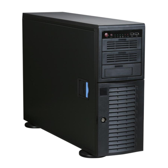
Advanced Chassis Setup This chapter covers the steps required to install components and perform simple maintenance on the SC743T-645 chassis. Following the component installation steps in the order given will eliminate most common problems. If some steps are unnecessary, skip ahead to the step that follows. Refer to Chapter 2 for instructions on installing the system as a 4U rackmount. - Page 64 A+ Workstation 4021A-T2 User's Manual Figure 6-1. Chassis Front View System LEDs USB Ports Main Power System Reset 5.25" Drive Bays (2) Floppy Drive (optional) 8 Serial ATA Drive Bays (behind locking bezel)
-
Page 65: Front Control Panel
Front Control Panel The front control panel must be connected to the JF1 connector on the serverboard to provide you with system status and alarm indications. A ribbon cable has bundled these wires together to simplify this connection. Connect the cable from JF1 on the serverboard (making sure the red wire plugs into pin 1) to the appropriate comnnec- tor on the front control panel PCB (printed circuit board). -
Page 66: System Fans
A+ Workstation 4021A-T2 User's Manual System Fans Four 8-cm chassis cooling fans (located in the center of the chassis) provide cooling airfl ow while two 8-cm exhaust fans expel hot air from the chassis. The chassis is also fi tted with an air shroud to concentrate the fl ow of cooling air over the areas where the most heat is generated. - Page 67 Chapter 6: Advanced Chassis Setup Figure 6-3. Removing a Chassis Fan...
-
Page 68: Drive Bay Installation
A+ Workstation 4021A-T2 User's Manual Drive Bay Installation Serial ATA Drives A total of six SATA drives may be housed in the SC743T-645 chassis. The drive IDs are preconfi gured as 0 through 5 in order from bottom to top (or from left to right if rackmounted). -
Page 69: Sata Backplane
Figure 6-4. Removing a SATA Drive Carrier Figure 6-5. Mounting a SATA Drive in a Carrier Important! Use extreme caution when working around the SATA backplane. Do not touch the backplane with any metal objects and make sure no cables touch the backplane or obstruct the airfl... -
Page 70: Installing Components In The 5.25" Drive Bays
A+ Workstation 4021A-T2 User's Manual Installing Components in the 5.25" Drive Bays The 4021A-T2 has two 5.25" drive bays. Components such as an extra fl oppy drive, IDE hard drives or CD-ROM drives can be installed into these 5.25" drive bays. Mounting Components in the Drive Bays Power down the system and then remove the top/left chassis cover to access the drive components. -
Page 71: Power Supply
Power Supply The 4021A-T2 has a single 645 watt power supply. This power supply has an auto- switching capability, which enables it to automatically sense and operate at a 100V or 240V (+- 10%) input voltage. Power Supply Failure If the power supply unit fails, the system will shut down and you will need to replace the power supply unit. - Page 72 A+ Workstation 4021A-T2 User's Manual Notes 6-10...
-
Page 73: Chapter 7 Bios
Chapter 7: BIOS Chapter 7 BIOS Introduction This chapter describes the AMIBIOS™ Setup utility for the H8DAE-2. The AMI ROM BIOS is stored in a fl ash chip and can be easily upgraded using a fl oppy disk-based program. Note: Due to periodic changes to the BIOS, some settings may have been added or deleted and might not yet be recorded in this manual. -
Page 74: Main Menu
A+ Workstation 4021A-T2 User's Manual Main Menu When you fi rst enter AMI BIOS Setup Utility, you will see the Main Menu screen. You can always return to the Main Menu by selecting the Main tab on the top of the screen with the arrow keys. -
Page 75: Advanced Acpi Confi Guration
Advanced ACPI Confi guration MCP55 ACPI HPET Table Use this setting to Enable or Disable the MCP55 ACPI HPET Table. IO55 ACPI HPET Table Use this setting to Enable or Disable the IOP55 ACPI HPET Table. ACPI Version Features Use this setting the determine which ACPI version to use. Options are ACPI v1.0, ACPI v2.0 and ACPI v3.0. - Page 76 A+ Workstation 4021A-T2 User's Manual Floppy/IDE/SATA Confi guration Onboard Floppy Controller Use this setting to Enable or Disable the onboard fl oppy controller. Floppy A Move the cursor to these fi elds via up and down <arrow> keys to select the fl...
- Page 77 Chapter 7: BIOS Block (Multi-Sector Transfer) Block mode boosts IDE drive performance by increasing the amount of data transferred. Only 512 bytes of data can be transferred per interrupt if block mode is not used. Block mode allows transfers of up to 64 KB per interrupt. Select "Disabled"...
- Page 78 A+ Workstation 4021A-T2 User's Manual Serial ATA0/1/2 Primary/Secondary Channel Highlight one of the items above and press <Enter> to access the submenu for that item. If a drive is present, information on that drive will be displayed here. LBA/Large Mode LBA (Logical Block Addressing) is a method of addressing data on a disk drive.
- Page 79 Select "Enabled" to allow AMI BIOS to use the S.M.A.R.T. to support hard drive disk. The options are Disabled, Enabled, and Auto. 32-Bit Data Transfer Select "Enabled" to activate the function of 32-Bit data transfer. Select "Disabled" to deactivate the function. The options are Enabled and Disabled. Hard Disk Write Protect Select Enabled to enable the function of Hard Disk Write Protect to prevent data from being written to HDD.
-
Page 80: Pcipnp Configuration
A+ Workstation 4021A-T2 User's Manual PCI/PnP Confi guration Load Onboard LAN Option ROM Use this setting to Enable or Disable the onboard option ROM. Clear NVRAM Select Yes to clear NVRAM during boot-up. The options are Yes and No. Plug & Play OS Select Yes to allow the OS to confi... -
Page 81: Advanced Chipset Control
Advanced Chipset Control NorthBridge Confi guration Memory Confi guration Memclock Mode This setting determines how the memory clock is set. Auto has the memory clock by code and Limit allows the user to set a standard value. MCT Timing Mode Sets the timing mode for memory. - Page 82 A+ Workstation 4021A-T2 User's Manual DRAM Scrub Redirect Allows system to correct DRAM ECC errors immediately, even with background scrubbing on. Options are Enabled and Disabled. DRAM BG Scrub Corrects memory errors so later reads are correct. Options are Disabled and various times in nanoseconds and microseconds.
-
Page 83: Processor & Clock Options
MAC1 LAN1 Bridge Settings are Enabled and Disabled for MAC1 LAN1 bridge. Legacy USB Support Select "Enabled" to enable the support for USB Legacy. Disable Legacy support if there are no USB devices installed in the system. "Auto" disabled Legacy support if no USB devices are connected. -
Page 84: Console Redirection
A+ Workstation 4021A-T2 User's Manual Serial Port 2 Mode Tells BIOS which mode to select for serial port 2. The options are Normal, IrDA and ASKIR. Parallel Port Address Select the base I/O address for the parallel port. The options are 378, 278 and 3BC. - Page 85 Chapter 7: BIOS Serial Port Mode Selects the serial port settings to use. Options are (115200 8, n, 1), (57600 8, n, 1), (38400 8, n, 1), (19200 8, n, 1) and (09600 8, n, 1). Flow Control Selects the fl ow control to be used for console redirection. Options are None, Hardware and Software.
-
Page 86: Hardware Monitor
A+ Workstation 4021A-T2 User's Manual Hardware Monitor CPU Overheat Alarm Use the "+" and "-" keys to set the CPU temperature threshold to between 65 C. When this threshold is exceeded, the overheat LED on the chassis will light up and an alarm will sound. -
Page 87: Ipmi Confi Guration
IPMI Confi guration View BMC System Event Log Pressing the Enter key will open the event log. Use the "+" and "-" keys to navigate through the system event log. Clear BMC System Event Log Selecting this and pressing the Enter key will clear the BMC system event log. Set LAN Confi... -
Page 88: Boot Menu
A+ Workstation 4021A-T2 User's Manual BMC Watch Dog Timer Action This setting is used to set the Watch Dog function. The options are Disabled, Reset System, Power Down and Power Cycle. Boot Menu This feature allows the user to confi gure the following items: Boot Device Priority This feature allows the user to prioritize the boot sequence from the available de- vices. -
Page 89: Security Menu
Security Menu AMI BIOS provides a Supervisor and a User password. If you use both passwords, the Supervisor password must be set fi rst. Change Supervisor Password Select this option and press <Enter> to access the sub menu, and then type in the password. - Page 90 A+ Workstation 4021A-T2 User's Manual Load Optimal Defaults To set this feature, select Load Optimal Defaults from the Exit menu and press <Enter>. Then Select "OK" to allow BIOS to automatically load the Optimal Defaults as the BIOS Settings. The Optimal settings are designed for maximum system performance, but may not work best for all computer applications.
-
Page 91: Appendix A Bios Error Beep Codes
BIOS Error Beep Codes During the POST (Power-On Self-Test) routines, which are performed each time the system is powered on, errors may occur. Non-fatal errors are those which, in most cases, allow the system to continue the boot-up process. The error messages normally appear on the screen. Fatal errors are those which will not allow the system to continue the boot-up pro- cedure. - Page 92 A+ Workstation 4021A-T2 User's Manual Notes...
-
Page 93: Appendix B Bios Post Checkpoint Codes
BIOS POST Checkpoint Codes When AMIBIOS performs the Power On Self Test, it writes checkpoint codes to I/O port 0080h. If the computer cannot complete the boot process, diagnostic equip- ment can be attached to the computer to read I/O port 0080h. B-1 Uncompressed Initialization Codes The uncompressed initialization checkpoint codes are listed in order of execution: Checkpoint... -
Page 94: Bootblock Recovery Codes
A+ Workstation 4021A-T2 User's Manual B-2 Bootblock Recovery Codes The bootblock recovery checkpoint codes are listed in order of execution: Checkpoint Code Description The onboard fl oppy controller if available is initialized. Next, beginning the base 512 KB memory test. Initializing the interrupt vector table next. - Page 95 B-3 Uncompressed Initialization Codes The following runtime checkpoint codes are listed in order of execution. These codes are uncompressed in F0000h shadow RAM. Checkpoint Code Description The NMI is disabled. Next, checking for a soft reset or a power on condition. The BIOS stack has been built.
- Page 96 A+ Workstation 4021A-T2 User's Manual Checkpoint Code Description Interrupt vector initialization is done. Clearing the password if the POST DIAG switch is on. Any initialization before setting video mode will be done next. Initialization before setting the video mode is complete. Confi guring the mono- chrome mode and color mode settings next.
- Page 97 Checkpoint Code Description The memory below 1 MB has been cleared via a soft reset. Clearing the memory above 1 MB next. The memory above 1 MB has been cleared via a soft reset. Saving the memory size next. Going to checkpoint 52h next. The memory test started, but not as the result of a soft reset.
- Page 98 A+ Workstation 4021A-T2 User's Manual Checkpoint Code Description The password was checked. Performing any required programming before WIN- BIOS Setup next. The programming before WINBIOS Setup has completed. Uncompressing the WINBIOS Setup code and executing the AMIBIOS Setup or WINBIOS Setup utility next.
- Page 99 Checkpoint Code Description Returned from adaptor ROM at E000h control. Performing any initialization required after the E000 option ROM had control next. Initialization after E000 option ROM control has completed. Displaying the system confi guration next. Uncompressing the DMI data and executing DMI POST initialization next. The system confi...
- Page 100 A+ Workstation 4021A-T2 User's Manual Notes...
-
Page 101: Appendix C System Specifi Cations
Appendix C: System Specifi cations Appendix C System Specifi cations Processors Single or dual 64-bit AMD Socket F, Opteron 2000 type processors Note: Please refer to our web site for a complete listing of supported processors. Chipset nVidia MCP55 Pro/IO-55 and NEC uPD720400 BIOS 8 Mb AMI®... - Page 102 A+ Workstation 4021A-T2 User's Manual Motherboard Model: H8DAE-2 (Extended ATX form factor) Dimensions: 12 x 13 in (305 x 330 mm) Chassis SC743T-645 Form Factor: tower/4U rackmount Dimensions (as tower): (WxHxD) 7 x 17.1 x 25.5 in. (178 x 434 x 648 mm) Weight Gross (Bare Bone): 64 lbs.
- Page 103 Appendix C: System Specifi cations Safety: EN 60950/IEC 60950-Compliant, UL Listed (USA), CUL Listed (Canada), TUV Certifi ed (Germany), CE Marking (Europe) California Best Management Practices Regulations for Perchlorate Materials: This Perchlorate warning applies only to products containing CR (Manganese Dioxide) Lithium coin cells.
- Page 104 A+ Workstation 4021A-T2 User's Manual Notes...
Need help?
Do you have a question about the AW-4021A-T2 and is the answer not in the manual?
Questions and answers