
Related Manuals for Hitachi VK-S274R


Summary of Contents for Hitachi VK-S274R
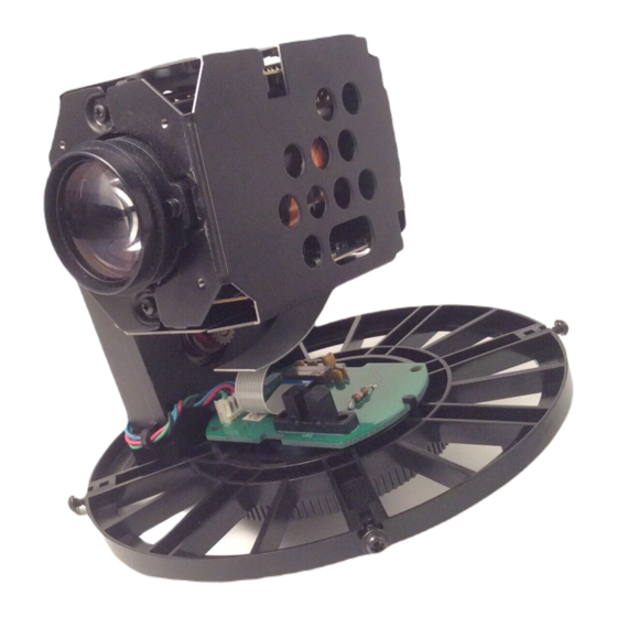
- Page 1 No. 8302E VK-S274R/S274ER VK-K274R/K274ER SERVICE MANUAL SPECIFICATIONS AND PARTS ARE SUBJECT TO CHANGE FOR IMPROVEMENT COLOR & B/W VIDEO CAMERA March 2003 Digital Media Division,Tokai...
-
Page 2: Table Of Contents
Table of Contents 6-1-4 Setting test equipment ......6-3 1 Safety Precaution for Repair ..... 1-1 6-1-5 Starting adjustment program (ZMAP) ..6-3 1-1 Cautions ........... 1-1 6-2 List of Adjustment Items ......6-5 1-2 Notes When Using Service Manual ..1-1 6-2-1 List of adjustments needed after 1-2-1 Value units used in parts list .... -
Page 3: Safety Precaution For Repair
The use of a substitute replacement component which does not have the same safety characteristics as the HITACHI recommended replacement one, shown in the parts list in this Service Manual, may create shock, fire, or other hazards. Product safety is continuously under review and new instructions are issued from time to time. -
Page 4: Identifications Of Sides A/B In Circuit Board Diagrams
Safety Precaution for Repair > Notes When Using Service Manual 1-2-3 Identifications of sides A/B in circuit board diagrams 1) Board having a pattern on one side and parts on both sides. Side A: Shows discrete parts, viewed from the pattern side. Side B: Shows leadless parts, viewed from the pattern side. -
Page 5: Electrostatic Protection Measures
Safety Precaution for Repair > Electrostatic Protection Measures 1-3 Electrostatic Protection Measures Semiconductor components, including optical pickups, may be damaged by static electricity charged on clothes, human body, etc. Take great care when handling it to avoid electrostatic damage. 1-3-1 Grounding for prevention of electrostatic damage Perform servicing in an environment where grounding is complete. -
Page 6: Lead-Free Solder
Safety Precaution for Repair > Lead-Free Solder 1-4 Lead-Free Solder To protect the global environment, lead-free solder is used in this product. Be sure to read the following before soldering. Caution Be sure to wear protective goggles so that no solder smoke or scattered solder enters the eye during servicing. -
Page 7: General Description
General Description 2-1 Overview VK-S274R/S274ER is a color chassis video camera; VK-K274R/K274ER is a Black-and-white chassis video camera: All these models incorporate an optical 22-power compact zoom lens. Models VK-S274R/S274ER/K274R/K274ER are successor cameras to VK-S274/S274E/K274/K274E. The signal process circuit is equipped with a digital signal processor (D.S.P.5) that is the same as that of VK-S274/S274E/K274/K274E. -
Page 8: Specifications
General Description > Specifications 2-3 Specifications The specifications in shaded columns are different from those of previous models. Design and specifications are subject to change without notice. VK-S274R/S274ER VK-S274/S274E Item VK-K274R/K274ER VK-K274/K274E Signal Format VK-S274R: NTSC VK-S274: NTSC VK-K274R: EIA B/W... - Page 9 General Description > Specifications Item VK-S274R/S274ER VK-S274/S274E VK-K274R/K274ER VK-K274/K274E Camera Mirror Functions Mosaic (Control Iris Control Auto Auto through Privacy Zone Off/On* (2 zone 2-D/8 zone 3-D) Off/On* (2 zone) RS-232C) Masking Freeze Extrenal Sync. Communication Selective (4.8k*/9.6k/19.2k/38.4/57.6k Fixed (4.8k bps)
-
Page 10: Comparison Of Main Control Ics
General Description > Comparison of Main Control ICs 2-4 Comparison of Main Control ICs The comparison of main control ICs in shaded columns are different from those of previous models Item VK-S274R/S274ER VK-S274/S274E VK-K274R/K274ER VK-K274/K274E Image Sensor VK-S274R: ICX278AK-L (IC1001) -
Page 11: Description Of Operation
Description of Operation 3-1 Structure Schematics 4 - M2 SCREWS for TRIPOD PLATE (These screws are limit of height keep as being less than 2 mm for "A") 50mm 89.5mm 4 - M2 SCREWS 12.5mm 77mm M2 SCREW 25mm 4 - M2 SCREWS for 90˚... -
Page 12: Microprocessor Pin Function Tables
Description of Operation > Microprocessor Pin Function Table 3-2 Microprocessor Pin Function Table 3-2-1 Camera microprocessor (IC1201: Camera µP) Active Abbreviation Function Level (Pulse) LD-DSP Activates data communication with IC1121 (CAMERA DSP). (Pulse) CS-DAC Not used. Open. (Pulse) CS-VAP GYRO-RST ----- CEON -----... - Page 13 Description of Operation > Microprocessor Pin Function Table Active Abbreviation Function Level (Pulse) Receives the vertical sync pulses that detect the iris detection area, from IC1121 (CAMERA DSP). (Pulse) FCUS-SEN Focus motor position detection input. ----- ----- Not used. Open. (Pulse) ZOOM-SEN Zoom motor position detection input.
- Page 14 Description of Operation > Microprocessor Pin Function Table Active Abbreviation Function Level ----- ----- Not used. Open. ----- ----- NC10 ----- ----- NC11 ----- ----- NC12 (Pulse) For data communications with IC1121 (CAMERA DSP), IC1202 (Pulse) (EEPROM), IC1203 (EEPROM). (Pulse) SCLK ----- -----...
-
Page 15: Troubleshooting
Troubleshooting 4-1 Trouble Diagnosis 4-1-1 Setting to service position Remove chassis R and chassis L, referring to “5. Disassembly and Reassembly”, and connect the camera as shown in Fig. 4-1-1. Note: To prevent short-circuit, always perform trouble diagnosis of camera on insulated mat. PC CIRCUIT BOARD SP CIRCUIT... -
Page 16: Trouble Diagnosis Flowchart
Troubleshooting > Trouble Diagnosis 4-1-2 Trouble diagnosis flowchart (1) No video (luminance) signal The test lands and components of circuit no. 1000-1099 are on the SP circuit board. The test lands and components of circuit no. 1100-1499 are TL1539 : 5V Refer to "(3) No power"... - Page 17 IC1001-7 : IC1001 faulty. CCD output signal Q1001 faulty. (2) No chroma signal [For VK-S274R/S274ER] The test lands and components of circuit no. 1000-1099 are on the SP circuit board. The test lands and components of circuit no. 1100-1499 are Refer to "(1) No video...
- Page 18 Troubleshooting > Trouble Diagnosis The test lands and components of circuit no. 1000-1099 are (3) No power on the SP circuit board. The test lands and components of circuit no. 1100-1499 are on the PC circuit board. The test lands and components of circuit no. 1500 and higher are on the CSR circuit board.
- Page 19 Troubleshooting > Trouble Diagnosis (4) No zoom and focus operation The test lands and components of circuit no. 1000-1099 are on the SP circuit board. The test lands and components of circuit no. 1100-1499 are L1301 faulty TL1301:7.2V on the PC circuit board. The test lands and components of circuit no.
- Page 20 Troubleshooting > Trouble Diagnosis C h e c k t h e 7 . 2 V ( V M ) I C 1 3 0 2 - 1 0 , 1 5 : 7 . 2 V l i n e . I C 1 2 0 1 f a u l t y .
- Page 21 Troubleshooting > Trouble Diagnosis (6) No focus lens operation The test lands and components of circuit no. 1000-1099 are on the SP circuit board. The test lands and components of circuit no. 1100-1499 are Does zoom See "(4)No zoom and on the PC circuit board.
- Page 22 Troubleshooting > Trouble Diagnosis ( 7 ) N o z o o m o p e r a t i o n The test lands and components of circuit no. 1000-1099 are on the SP circuit board. Does focus operate See "(4) No zoom and The test lands and components of circuit no.
- Page 23 Troubleshooting > Trouble Diagnosis (8) No auto focus operation Does zoom See "(4) No zoom and operate focus operation." normally? The test lands and components of circuit no. 1000-1099 are on the SP circuit board. Connect an The test lands and components of circuit no. 1100-1499 are on the PC circuit board. oscilloscope The test lands and components of circuit no.
- Page 24 Troubleshooting > Trouble Diagnosis TL1347 to 1350: Lens unit faulty. Pulses IC1302-2,4,24:3V Check the 3V line Check the 7.2V (VM) IC1302-10,15:7.2V line I C 1 2 0 1 f a u l t y . TL1312 :Pulse I C 1 2 0 1 f a u l t y . IC1302-23:Pulse I C 1 2 0 1 f a u l t y .
-
Page 25: Disassembly And Reassembly
Chassis R reverse order to removal unless otherwise specified. 1) and 2) Chassis L Note: When replacing components in the VK-S274R/S274ER/K274R/ 3) to 5) PC Circuit Board K274ER, be sure to use only those shown in "Replacement Parts List". 6) and 7) - Page 26 Disassembly and Reassembly > Disassembly PC Circuit Board (Fig. 5-2-2) 3) Disconnect the flat cable from the PC circuit board. To connect flat cables, perform the procedure in Fig. 5-2-3. 4) Remove one screw [B]. 5) Remove the PC circuit board in the direction of the arrow. CSR Circuit Board (Fig.
-
Page 27: Adjustment
Adjustment 6-1 Preparations for Adjustment All adjustments are performed using the adjustment program (ZMAP: Zoom camera Manual Adjustment Program) and personal computer (PC). If error message appears during adjustment, refer to "6-8 Error Messages and Countermeasure". 6-1-1 List of equipment and jigs DSP Interface Connect DSP-R Jig C12 Light Balancing... -
Page 28: Connections For Adjustment
Adjustment > Preparations for Adjustment 6-1-3 Connections for adjustment Connect the video camera to the test equipment and jigs as shown in Fig. 6-1-1 LIGHT VIDEO CAMERA VECTORSCOPE 9PIN FLAT CABLE (ACCESSORY) PG1601 INPUT OUTPUT OSCILLOSCOPE DSP INTERFACE CONNECT JIG CH1 CH2 VIDEO 1 2 3 4 5 6 7 8 9... -
Page 29: Setting Test Equipment
Adjustment > Preparations for Adjustment 6-1-4 Setting test equipment (1) Oscilloscope The names of switches, knobs, modes, etc. of oscilloscope may vary slightly depending on the manufacturer or model. Since some oscilloscopes may have switches, etc. other than the above that must be set, see the instruction manual of the particular oscilloscope for details. - Page 30 Adjustment > Preparations for Adjustment 7) The ZMAP will start: Make sure that the model select (Continued from preceding page) screen appears on the PC display. (See the model select Model select screen screen) *********************************************************** If the model select screen does not appear, make sure of MODEL SELECT *********************************************************** the following:...
-
Page 31: List Of Adjustment Items
Camera Adjustment (Adjustment) Auto Iris To set the iris control data. White Balance To input the automatic white balance [For VK-S274R/S274ER] control data. Chroma Gain To set the color satuation under the [For VK-S274R/S274ER] reference color temperrature. Auto Focus... -
Page 32: Adjustment Flowchart
CHROMA GAIN [ESC] RETURN TO MAIN MENU Please select [1] - [3] or [ESC] Input: 2 Input: 1 Input: 3 [For VK-S274R/S274ER] Auto Iris Control White Balance Chroma Gain ADJUSTMENT FINISHED PRESS ANY KEY << ADJUSTMENT OF WHITE BALANCE >>... -
Page 33: Data Initialize
Adjustment > Data Initialize / Electronic Volume 6-3 Data Initialize Restriction: 1) This procedure initializes the adjustment data in EEPROM (including the adjustment data). Any time you replace the EEPROM, be sure to perform this procedure. Generally, this procedure is not necessary after replacing other components. 2) After completing this adjustment, be sure to perform all adjustment items as follows. -
Page 34: Cds Sampling Pulse Adjustment
Adjustment > Electronic Volume / Adjustment (Camera Adjustment) 6-4-1 CDS sampling pulse adjustment Electronic volume menu *********************************************************** Incompleted Phenomenon ELECTRIC VOLUME Diagonal beats and horizontal noise occur. *********************************************************** CDS SAMPLING PULSE Condition: [ESC] RETURN TO MAIN MENU Please select [1] or [ESC] Leave the video camera for more than 2 minutes until the circuits are stabilized after turning it on, then start Input 1. -
Page 35: Auto Iris Control Adjustment
If this happens, press the Esc key to restore the MS-DOS screen, and then restart the ZMAP. 6-5-2 White balance adjustment Adjustment menu [For VK-S274R/S274ER] *********************************************************** ADJUSTMENT Incompleted Phenomenon *********************************************************** 1) Color of the subject is different from that of the picture. -
Page 36: Chroma Gain Adjustment
Adjustment > Adjustment (Camera Adjustment) 6-5-3 Chroma gain adjustment (Figs. 6-5-1, 6-5-2, 6-5-3) [For VK-S274R/S274ER] Adjustment menu Incompleted Phenomenon *********************************************************** ADJUSTMENT 1) Color of the picture is denser than that of the subject. *********************************************************** 2) Color of the picture is lighter than that of the subject. -
Page 37: Auto Focus
Adjustment > Auto Focus 6-6 Auto Focus Main menu *********************************************************** Input D to PC on the main menu screen to display the AF MANUAL ADJUSTMENT PROGRAM *********************************************************** menu screen. Input the appropriate adjustment number to DATA INITIALIZE PC. Pressing the Esc key on the AF menu screen will restore ELECTRIC VOLUME ADJUSTMENT the main menu screen. -
Page 38: Af Noise Level Adjustment
Adjustment > Auto Focus 6-6-2 AF noise level adjustment AF menu Incompleted Phenomenon *********************************************************** AUTO FOCUS ADJUSTMENT 1) It takes time until a subject is brought into focus. *********************************************************** ADJUSTMENT OF ZOOM/FOCUS TRACKING 2) Correct focus is not obtained. ADJUSTMENT OF AF NOISE LEVEL CHECK OF ZOOM/FOCUS TRACE Condition [ESC] RETURN TO MENU... -
Page 39: Spot Noise
Adjustment > Spot Noise 6-7 Spot Noise Spot noise refers to bright points that appear on the screen, Main menu *********************************************************** which are caused by a defect in pixel of image sensor. MANUAL ADJUSTMENT PROGRAM *********************************************************** DATA INITIALIZE Note: ELECTRIC VOLUME ADJUSTMENT 1) Perform this adjustment after specified components have AUTO FOCUS... -
Page 40: Error Messages And Countermeasure
Adjustment > Error Messages and Countermeasure 6-8 Error Messages and Countermeasure A message may appear while you are adjusting the video camera. If a message appears, refer to the following table and take appropriate corrective action. Error Messages Countermeasure When adjusting the electric volume and adjustment CAN'T ADJUST WHITE BALANCE 1) The subject is too bright or too dark. - Page 41 Adjustment > Error Messages and Countermeasure Error Messages Countermeasure TOO BRIGHT 1) The subject is too bright. PRESS ANY KEY 2) Move the camera further away from the light box. TOO DARK 1) The subject is too dark. PRESS ANY KEY 2) Check the light box.
-
Page 42: Exploded View And Parts List
Exploded View and Parts List 7-1 Exploded View Note: Components without any numbers in exploded views had not been assigned as service parts as of the date of issue of this manual. PC CIRCUIT BOARD [Component Replacement] SP CIRCUIT BOARD [Component Replacement] CSR CIRCUIT BOARD [Component Replacement]... -
Page 43: Replacement Parts List
7-2 Replacement Parts List : To Be Reported 7-2-1 Mechanical Parts List 7-2-2 Electrical Parts List SYMBOL SYMBOL P-NO DESCRIPTION P-NO DESCRIPTION MECHANISM SECTION CAPACITORS NA31542 CHASSISE,L C1001 0893107 CERAMIC CHIP 5PF+-0.25% 50V NA31552 CHASSISE,R C1002 AA00393R CHIP CERAMIC 1.0UF+80-20% 50V KQ10752 LENS ASSY C1003... - Page 44 SYMBOL SYMBOL P-NO DESCRIPTION P-NO DESCRIPTION C1180 0893123 CERAMIC CHIP 56PF+-5% 50V C1520 AA00422R CERAMIC CHIP 10UF 16V C1182 0893225 CERAMIC CHIP 0.1UF+80-20% 16V C1521 0893062 CERAMIC CHIP 1UF+80-20% 16V C1183 0893112 CERAMIC CHIP 9.0PF+-0.5% 50V C1522 AA01001R CHIP CAPACITOR 1.0UF 25V C1185 0893101 CERAMIC CHIP 0.5PF+-0.25% 50V...
- Page 45 SYMBOL SYMBOL P-NO DESCRIPTION P-NO DESCRIPTION R1162 0790037 CHIP RESISTOR 1KOHM+-5% 1/16W R1375 0790036 CHIP RESISTOR 820 OHM+-5% 1/16W R1164 AQ00205R CHIP RESISTOR 2.7KOHM+-1% 1/16W R1376 0790047 CHIP RESISTOR 5.6KOHM+-5% 1/16W R1165 AQ00194R CHIP RESISTOR 1.0KOHM+-1% 1/16W R1378 0790047 CHIP RESISTOR 5.6KOHM+-5% 1/16W R1173 0790051 CHIP RESISTOR 10KOHM+-5% 1/16W...
- Page 46 SYMBOL SYMBOL P-NO DESCRIPTION P-NO DESCRIPTION D1502 5337352 DIODE MA132WA L1302 BA10577R COIL 10UH D1503 CC10291R DIODE 1SS353 L1501 BA10579R COIL 22UH D1504 5337372 DIODE SB07-03C L1503 BA11236R COIL 68UH D1505 5337372 DIODE SB07-03C L1504 BA11233R COIL 22UH D1506 5337372 DIODE SB07-03C L1505 BA11235R...
-
Page 47: Schematic, Circuit Board And Block Diagrams
Schematic, Circuit Board and Block Diagrams 1 Wiring Diagram PG1302 PG1241 LENS UNIT PG1001 PG1002 PG1501 PG1601 OUTPUT - 1 - - 1 -... -
Page 48: Schematic Diagrams
2 Schematic Diagrams 2-1 SP Schematic Diagram -7.0 10.8 10.5 10.0 -7.0 -7.0 15.0 10.5 IC1001 -7.1 [S274R] [S274ER] [K274R] [K274ER] IMAGE SENSOR 15.1 -7.0 -7.0 -7.1 PG1241 17.0 12.0 -2.0 10.0 CODE PART NAME 2SC2620-QC 1SS353 NOTE:VOLTAGES ARE MEASURED WHEN CAMERA IS POINTED AT THE COLOR BAR CHART. -
Page 49: (For Display)
2-2 PC Schematic Diagram (For Display) (For Display) CDS/AGC & A/D CONV (For Printing) PG1001 CAMERA DSP BLM11B750SPT BLM11B750SPT BLM11P600SPT DRAM -0.5 LENSE UNIT [S274R/S274ER] INV. TC7SHU04FUL INV. 0.5p 0.5p S274ER/K274ER S274R/K274R X1172 28.5MHz 28.6MHz NOTE: VOLTAGES ARE MEASURED WHEN CAMERA IS POINTED AT THE COLOR BAR CHART. -
Page 50: (For Printing) A-A
2-3 PC Schematic Diagram (For Printing) - 4 -... -
Page 51: (For Printing) A-B
2-4 PC Schematic Diagram (For Printing) - 5 -... - Page 52 2-5 CSR Schematic Diagram LEVEL SHIFT VCO/PHASE COMPA. LEVEL SHIFT BLM21A121SPT FLC800Z16SMMZ OUTPUT [S274R/S274ER] [S274R/S274ER] [K274R/K274ER] NOTE: VOLTAGES ARE MEASURED WHEN CAMERA IS CODE PART NAME POINTED AT THE COLOR BAR CHART. 2SB1424 (AE) 2SB1462 2SC4081 2SC4617 2SC2620-QC DTA143EE DTC144EE DTC114YE XP4401 (AE)
-
Page 53: Circuit Board Diagram
3 Circuit Board Diagrams 3-1 PC Circuit Board Diagram TL1312 TL1301 TL1311 TL1346 TL1336 TL1333 TL1335 TL1345 TL1344 TL1348 TL1347 TL1350 TL1332 TL1349 TL1331 TL1334 TL1236 TL1238 TL1154 TL1240 S274R/S274ER K274R/K274ER PC -SIDE A- PC -SIDE B- S274ER/K274ER S274R/K274R Q1153 2SB1462 Not Provided X1172... -
Page 54: Sp Circuit Board Diagram
3-2 SP Circuit Board Diagram 3-3 CSR Circuit Board Diagram S274R/S274ER K274R/K274ER C1626 10uF/6.3V Not Provided S274R/S274ER K274R/K274ER C1650 680p Not Provided C1608 Not Provided 0.1uF Q1607 2SC2620 Not Provided C1610 0.1uF Not Provided Q1609 XP4401 Not Provided C1617 22p [S274R],12p [S274ER] Not Provided Q1610 2SC4617... -
Page 55: Identification Parts Location
3-4 Identification of Parts Location Symbol Parts Symbol Parts Symbol Parts Symbol Parts Symbol Parts Symbol Parts Symbol Parts Symbol Parts Symbol Parts Symbol Parts Location Location Location Location Location Location Location Location Location Location C1188 A-1D IC1202 A-1C R1203 B-2D R1375 A-2D... -
Page 56: Block Diagrams
4. Block Diagrams 4-1 Overall Block Diagram S274R S274ER K274R K274ER IC1121 IC1122 CAMERA DSP DRAM L1603 Provided IC1101 IC1001 C1617 Not Provided PG1001 PG1241 CDS/AGC & A/D CONV IMAGE Q1001 (1/2) (1/2) 3.58MHz 4.43MHz SENSOR BUF. Y/CHROMA 2-11 136-144 DIGITAL PROCESS AUTO... -
Page 57: Power Block Diagram
4-2 Powe Block Diagram IC1502 IC1301 PG1501 PG1002 PG1001 PG1241 PG1601 CP1601 7.2V 7.2V 7.2V F1601 L1301 19,20 19,20 29,30 29,30 7.2V 10,15 ZOOM D1601 MOTOR 2,4,24 DRIVE L1501 IC1302 10,15 FOCUS Q1501 MOTOR IC1501 L1503 2,4,24 DRIVE IC1601 IC1351 L1601 13,16 L1202... - Page 58 VK-S274R/S274ER TK No. 8302E Digital Media Division,Tokai VK-K274R/K274ER Copyright © Hitachi, Ltd. 2003. All rights reserved. Printed in Japan (I)
Need help?
Do you have a question about the VK-S274R and is the answer not in the manual?
Questions and answers