Table of Contents
Advertisement
Advertisement
Table of Contents

Related Manuals for Falcon DVR


Summary of Contents for Falcon DVR
-
Page 3: Compliance Notice Of Fcc
4-Channel Digital Video Recorder WARNING RISK OF ELECTRIC SHOCK DO NOT OPEN WARNING: TO REDUCE THE RISK OF ELECTRIC SHOCK, DO NOT REMOVE COVER (OR BACK). NO USER-SERVICEABLE PARTS INSIDE. REFER SERVICING TO QUALIFIED SERVICE PERSONNEL. The lightning flash with arrowhead symbol, within an equilateral triangle, is intended to alert the user to the presence of uninsulated "dangerous voltage"... -
Page 4: Important Safeguards
User’s Manual Important Safeguards 1. Read Instructions 14. Damage requiring Service All the safety and operating instructions should be read before the Unplug this equipment from the wall outlet and refer servicing to appliance is operated. qualified service personnel under the following conditions: A. -
Page 5: Table Of Contents
4-Channel Digital Video Recorder Table of Contents Chapter 1 ─ Introduction ......................1 Features ..........................1 Technical Overview ........................ 1 Chapter 2 ─ Installation ......................3 Package Contents ........................3 Required Installation Tools ....................3 Video Input......................... 3 Video Loop Through ......................3 Video Out ........................... - Page 6 User’s Manual Alarm-Out ........................27 Display ..........................27 Remote Control ....................... 29 Recording Setup ........................29 Record ..........................29 Schedule .......................... 31 Pre-Event ......................... 32 Event Setup ......................... 33 Alarm-In ........................... 33 Motion Detection ......................34 Video Loss ........................36 Video Blind........................
- Page 7 Specifications ........................66 List of Illustrations Figure 1 ─ Typical DVR installation......................2 Figure 2 ─ DVR rear panel......................... 3 Figure 3 ─ DVR front panel........................7 Figure 4 ─ Infrared Remote Control......................9 Figure 5 ─ Login screen........................... 10 Figure 6 ─...
- Page 8 User’s Manual Figure 47 ─ Motion Detection Actions setup screen ................35 Figure 48 ─ Video Loss Settings setup screen..................36 Figure 49 ─ Video Loss Actions setup screen..................36 Figure 50 ─ Video Blind Settings setup screen..................37 Figure 51 ─...
-
Page 9: Chapter 1 ─ Introduction
The DVR can be set up to alert you when the hard disk drive is full, or it can be set to record over the oldest video once the disk is full. -
Page 10: Figure 1 ─ Typical Dvr Installation
User’s Manual Figure 1 ─ Typical DVR installation. -
Page 11: Chapter 2 ─ Installation
RAS Software CD and User’s Manual Infrared Remote Control Required Installation Tools No special tools are required to install the DVR. Refer to the installation manuals for the other items that make up part of your system. Figure 2 ─ DVR rear panel. -
Page 12: Video Out
AI 1 to 4 (Alarm-In): You can use external devices to signal the DVR to react to events. Mechanical or electrical switches can be wired to the AI (Alarm-In) and G (Ground) connectors. The threshold voltage is 4.3V and should be stable at least 0.5 seconds to be detected. -
Page 13: Network Port
Poke the straightened paperclip into the unlabeled hole to the left of the Network port, and turn the DVR on. Hold the reset switch until the DVR turns on and live monitoring screen appears. Release the reset switch. All of the DVR’s settings are now at the original settings it had when it left the factory. Network Port The DVR can be networked using the 10/100Mb Ethernet connector. - Page 14 User’s Manual...
-
Page 15: Chapter 3 ─ Configuration
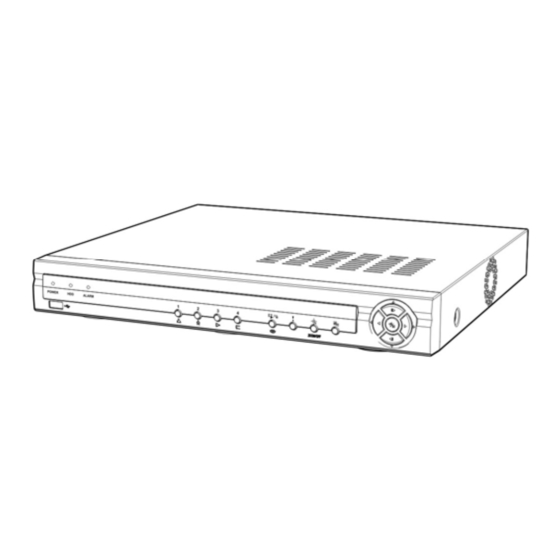
The POWER LED is lit when the unit is On. HDD LED The HDD LED flickers when the DVR is recording or searching video on the hard disk drive. ALARM LED The ALARM LED is lit when alarm output or internal buzzer is activated. -
Page 16: Enter/Pause Button
When entering the playback mode, video is paused. Pressing the arrow button plays back video at regular speed. The screen displays when the DVR is in the Pause mode and the screen displays when the DVR is playing back video. The button is also used to load a Preset View in the PTZ mode. -
Page 17: Usb Port
Position external drives close enough to the DVR so that you can make the cable connections, usually less than 6 feet. Use the USB cable provided with the hard disk drive to connect it to the DVR. -
Page 18: Setup Screen
Menu in the Live Monitoring menu to enter the setup screen. While setting up the DVR, there will be many opportunities to enter names and titles. When making these entries, a Virtual Keyboard will appear. Use the arrow keys to highlight the character you want in the name or title and press button. -
Page 19: System Setup
The box beside Version displays the software version of the DVR. To upgrade the software, connect a USB device containing the upgrade package file to the DVR. Highlight Upgrade… button. The Upgrade screen appears. and press the The screen displays the upgrade package file names that are available. -
Page 20: Date/Time
Highlighting Clear All Data… and pressing the button will clear all video data. You will be asked to verify that you wish to clear all data before the DVR erases the video data. Clear All Data… will not clear the System Log. Date/Time Highlight Date/Time in the System menu and press the button. -
Page 21: Figure 10 ─ Date/Time Setup Screen
Highlighting the Time Sync. tab causes the Time Sync. setup screen to display. You can set up time synchronization between the DVR and standard time servers that are available in most time zones and countries, or between the DVR and another DVR. -
Page 22: Storage
You will be asked to verify that you wish to clear all data before the DVR erases the video data. Clear All Data… will not clear the System Log. Highlight the Status tab, and the Storage Status setup screen displays. -
Page 23: User
You will be asked to confirm that you want to delete the User or Group. To delete the User currently logged into the DVR on a local system or a PC running RAS, log the user out of the system first and then delete the user. -
Page 24: Wizard
(not supplied). Highlighting the box beside Auto Login allows you to select a User to be automatically logged in when the DVR is powered up. It can also be set to never automatically login a user. -
Page 25: Figure 17 ─ Quick Setup Wizard Screen
– Continuous & Motion Event Record – Continuous Record NOTE: You should understand each recording mode before setting the DVR’s recording method. Record Video Quality Setup Select the desired video quality profile from: – Higher Video Quality Priority Profile –... -
Page 26: Figure 18 ─ Network Setup Wizard Screen
Setup Wizard. If you selected the Go to Network Setup, select the Next button to start the Network Setup Wizard. Figure 18 ─ Network Setup Wizard screen. Internet Connection Select whether or not your DVR is connected to the Internet. -
Page 27: Shutdown
Enable NAT: Select the box to use the NAT (Network Address Translation) device. DVR Name: Enter the DVR name to be registered on the DVRNS server. Check: Select the box to check whether or not the name you entered can be used. -
Page 28: Network Setup
NOTE: Depending on network conditions, audio might be interrupted or out of synchronization during transmission. NOTE: Recorded audio might NOT be played properly on a PC running RAS when the DVR is connected to more than two RAS search programs at the same time. -
Page 29: Figure 22 ─ Lan (Manual) Setup Screen
NOTE: You will need to get the appropriate Port Numbers for each RAS and WebGuard related program (Admin, Callback, Watch, Search and Audio) from your network administrator. NOTE: Do NOT use the same port number for two different programs, otherwise, the DVR cannot be connected with the PC running RAS or WebGuard. -
Page 30: Figure 23 ─ Dvrns Setup Screen
IP address of the DVR configured by the ADSL network. NOTE: If the DVR is configured for DHCP or an ADSL network, the IP address of the DVR might change whenever the unit is turned on. Highlight the DVRNS tab, and the DVRNS setup screen displays. -
Page 31: Figure 24 ─ Rtsp Setup Screen
NOTE: Selecting Use Mobile sets the WebGuard service to be enabled automatically regardless of your WebGuard settings. NOTE: You can access a remote DVR and monitor live video images using media players, such as VLC Player, supporting RTSP service. Start the media player on your local PC and enter “rtsp://ID:Password@IP address: RTSP port number/‘channel number’”, or start Internet Explorer on your Blackberry or other mobile devices and... -
Page 32: Notification
Figure 25 ─ WebGuard setup screen. Notification The DVR can be set up to send an email or to contact a computer running RAS (Remote Administration System) when an event occurs. Highlight Notification in the Network menu and press the button. -
Page 33: Devices Setup
You can enter up to five IP addresses. Highlight the box beside Retry and enter the number of times you would like the DVR to try contacting the computer. You can select from 1 to 10 retries. Figure 27 ─ Notification Callback setup screen. -
Page 34: Audio
You will need to connect the camera to the RS232 or RS485 connector on the back of the DVR following the camera manufacturer’s instructions. You can assign IDs to each camera by highlighting the box under the ID heading and pressing the button. -
Page 35: Alarm-Out
When set to Event, the Alarm-Out is only active when there is an Event during the scheduled time. The Alarm-Out box allows you to select between Alarm Output and Beep (DVR’s internal buzzer). box allows you to delete an alarm output schedule. You will be asked to confirm whether or not you really wish to delete the schedule. -
Page 36: Figure 34 ─ Display Osd Setup Screen
Figure 34 ─ Display OSD setup screen. Free Space – The icon displays when the DVR is in the Recycle mode, and the percentage of available storage space displays when the DVR is not in the Recycle mode. Date/Time – The current date and time information displays. -
Page 37: Remote Control
Highlight Setup… and select the correct Baud Rate, Parity, Data Bits and Stop Bits for the device you are connecting to the DVR. Highlight the box beside Remote Control Product and select the device from the list. -
Page 38: Figure 39 ─ Record Setup Screen
When this feature is On, the DVR records over the oldest “time-lapse” video once all available storage has been used in the Recycle mode, so more event video can be saved. -
Page 39: Schedule
Choose from: No Record, Time, Event and Time & Event. (Simple Mode Only) When the DVR is in the No Record mode, it will not record during the preset day and time range as long as the Panic button is not pressed. -
Page 40: Pre-Event
NOTE: Channels that are not defined will use the setting values of the previous schedule item. NOTE: When multiple events are detected at the same time from a specific channel, the DVR will record event video with the high setting values if the ips, Quality, Resolution and Dwell values of events are different from each other. -
Page 41: Event Setup
Figure 44 ─ Alarm-In Settings setup screen. You can set up the DVR to start panic recording whenever it senses an input on one of its alarm input connectors. Highlight the box beside Panic Record and press the button. A list of Alarm Inputs appears, and you can select which alarm input you want associated with panic recording. -
Page 42: Motion Detection
Highlight the desired box under the PTZ heading, and press the button. A list of PTZ presets appear. Select the preset position for each PTZ camera, where you want PTZ cameras to move to whenever the DVR detects an input on the associated alarm input. -
Page 43: Figure 47 ─ Motion Detection Actions Setup Screen
Highlight the box beside Motion Ignoring Interval and press the button. A list of intervals ranging from 1 to 5 seconds or Never appears. The DVR will not log and notify motion events occurred during the preset interval range. -
Page 44: Video Loss
Select between Alarm Output and Beep (DVR’s internal buzzer) that you would like to activate and to sound whenever the DVR detects video loss on the selected camera. NOTE: For the Alarm-Out action, the alarm output and beep you select should be set to the Event mode in the Alarm-Out setup screen (Schedule tab). -
Page 45: Video Blind
Select between Alarm Output and Beep (DVR’s internal buzzer) that you would like to activate and to sound whenever the DVR detects video blind on the selected camera. NOTE: For the Alarm-Out action, the alarm output and beep you select should be set to the Event mode in the Alarm-Out setup screen (Schedule tab). -
Page 46: Text-In
Start string. Refer to the device manufacturer’s documentation for the text string that the device first sends when a transaction starts. If you want the DVR to react to any character sent from the text input device, you will want to turn On Any Character. Highlight Any Character, and press the button to toggle between On and Off. -
Page 47: System Event
Set the length of time to wait for the new text string. The DVR will consider a transaction complete if no new text strings are entered between the last text input and the dwell time out. You can adjust the Time Out dwell from 5 seconds to 15 minutes. -
Page 48: Figure 56 ─ Storage Setup Screen
Highlighting the box under the Interval heading beside each alarm-in and pressing the button allows you to change the interval that you want the DVR to run self-diagnostics on Alarm Inputs. You can select from 1 hr. to 30 days or Never. -
Page 49: Event Status
Figure 58 ─ Event Status setup screen. Disk Almost Full will be highlighted when the DVR is not in the Recycle mode and the level of disk usage reaches the Disk Almost Full percentage you made in the System Event setup screen on the Event menu. Disk Full will be highlighted when the DVR is not in the Recycle mode and all available storage space has been used. - Page 50 User’s Manual...
-
Page 51: Chapter 4 ─ Operation
However, you have much greater control over recording and playing back video. You can establish recording schedules based on time of day and day of the week. The DVR allows you to search through the recorded video using much more sophisticated tools than those available with VCRs. -
Page 52: Live Monitoring Menu
Alarm Reset Selecting (Alarm Reset) in the Live Monitoring menu resets the DVR’s outputs including the internal buzzer during an alarm. It is the same as pressing any button on the front panel when the alarm is activated. Panic... -
Page 53: Zoom Mode
NOTE: When a camera is set up as Covert 1, the DVR displays the camera title and status icons on the covert video. When set up as Covert 2, the DVR displays only the camera title on the covert video. -
Page 54: Using A Mouse
Using a Mouse You can use a mouse instead of the front panel buttons to perform many of the DVR functions. In the Live Monitoring mode or Search mode, moving the mouse pointer to the left edge of the screen displays the following Mouse Display menu. -
Page 55: Recording Video
Recycle On or Recycle Off. The factory default is Recycle On. It does this by recording over the oldest video once the hard disk is full. Setting the DVR to Recycle Off causes it to stop recording once the hard disk is full. -
Page 56: Recording Audio
Recording Audio If the DVR was set up to record audio, it will record audio from up to four inputs when video is recording. The DVR will not record audio when the recording speed is set to less than 1 ips. -
Page 57: Search Menu
4-Channel Digital Video Recorder Search Go To Export Camera Menu Alarm Reset Panic Data Source Exit Figure 63 ─ Search menu. NOTE: The Search menu also can be displayed by moving the mouse pointer to the top of the screen. Search Menu Search Selecting... -
Page 58: Event Log Search
(Data Source) in the Search menu allows you to select the data source to be searched. Selecting Record Selecting searches recorded data on primary storage installed in the DVR, and selecting Other searches recorded data on storage used for another DVR then installed in this DVR. - Page 59 It toggles between On and Off. You will only be able to turn the Check Time Overlap on or off if a user-defined date and time is set to From and To. If the DVR’s date and time have been reset, it is possible for the DVR to have more than one overlapping start and stop time. When set to On, you will be asked to select one of the overlapping start and stop time.
-
Page 60: Record Table Search
NOTE: If the DVR has images recorded in more than one recording mode in the same time range, the recording status bar displays recording information in the following priority order: Panic ... -
Page 61: Motion Search
Motion Search The Motion Search… can be selected from the Search menu while the DVR displays the camera full screen. The Motion Search screen displays a list of motion events. Use the arrow buttons to highlight the event for which you would like to... -
Page 62: Text-In Search
User’s Manual Text-In Search The DVR maintains a log of each time there is Text Input. The Text-In Search screen displays this list. Use the arrow buttons to highlight the event for which you would like to see video. Pressing the (Enter) button will extract the video associated with the Text Input and display the first image of the event. -
Page 63: Clip-Copy
NOTE: While copying video clips on the CD-RW, the recording speed might decrease. The DVR automatically assigns a file name to the video clip. However, you can give the video clip file a different name. Highlight the box beside File Name and press the button. - Page 64 However, the file size for the One-Touch Clip Copy is limited to 2GB. You can use other functions on the DVR while video is being backed up. To do this, highlight the Close button and button. You can return to the Clip-Copy screen at any time to check the progress.
-
Page 65: Appendix
12. Right click the newly created hard disk drive icon and select “Format”. 13. In the Format Screen, select “Full” as the “Format type” and click “Start”. 14. After formatting is complete, connect the USB hard disk drive to the DVR. -
Page 66: Text-In Search Examples
User’s Manual Text-In Search Examples Search Example I 123456789012345678901234567890123456789012345678901234567890 Item Unit price amount ================================================== Coke 2.20 | 1(s) | $ 2.20 Fanta 2.20 | 1(s) | $ 2.20 Hotdog 3.50 | 3(s) | $ 10.50 Pepsi 1.95 | 1(s) | $ 1.95 ================================================== total : $... -
Page 67: Webguard
Or, “http://www.dvronline.net” (Entering the DVR IP address or the DVR name will be required when logging in) – NOTE: You will need to get the appropriate IP address for the DVR you want to connect to and the WebGuard port number from your network administrator. -
Page 68: Web Monitoring Mode
Command Prompt with elevated administrator permissions. Restart your computer to apply the changes. Web Monitoring Mode WebWatch is a remote web monitoring program that allows you to monitor live video transmitted in real-time from the remote DVR. ① Click the to log out the WebGuard program. ② Click the to access to the web search mode. -
Page 69: Web Search Mode
WebGuard system and a DVR. Web Search Mode WebSearch is a remote web search program that allows you to search recorded video on the remote DVR. NOTE: The remote site connection in the Web Search mode will automatically be disconnected if there is no... - Page 70 ③ Position the mouse pointer on the WebSearch logo to see the version of the WebGuard program. ④ The DVR information window displays the time information of recorded data on the remote DVR and login information of WebGuard.
-
Page 71: Troubleshooting
Confirm that the camera has power. Check camera lens settings. If hard disk drive is full, you will either need to delete video or set the DVR to DVR has stopped recording the Overwrite Mode. When the DVR is in the Pre-Event recording mode, the yellow... -
Page 72: Map Of Screens
User’s Manual Map of Screens... -
Page 73: System Log Notices
4-Channel Digital Video Recorder System Log Notices Boot Up Setup End Format Disk Shutdown Remote Setup Change Disk Full Restart Remote Setup Fail Disk Config Change Upgrade Setup Imported Auto Deletion Upgrade Fail Setup Import Failure Search Begin Time Change Setup Exported Search End Time Zone Change... -
Page 74: Specifications
User’s Manual Specifications VIDEO Signal Format NTSC or PAL (Auto Detect) Video Input Composite: 4 looping inputs, 1 Vp-p, auto-terminating, 75 Ohms Composite: 1 BNC, 1 Vp-p, 75 Ohms Monitor Outputs VGA: 1 (Auto Detect) Composite: 720x480 (NTSC), 720x576 (PAL) Video Resolution VGA: 800x600, 1024x768, 1280x1024@60Hz Playback/Record Speed...
Need help?
Do you have a question about the DVR and is the answer not in the manual?
Questions and answers