
Related Manuals for Advance acoustic SC3000 26” Disc


Summary of Contents for Advance acoustic SC3000 26” Disc
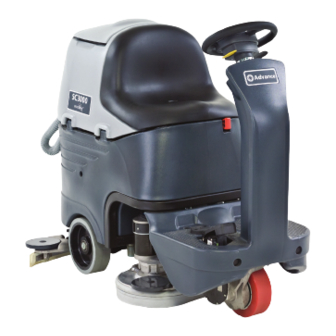
- Page 1 SC3000 26” Disc SERVICE MANUAL ENGLISH Advance models: 9087267020 - 26” Disc - EcoFlex™ + Charger 9099052000(3)2011-07...
-
Page 3: Table Of Contents
SERVICE MANUAL ENGLISH TABLE OF CONTENTS GENERAL INFORMATION .............................. 3 CONVENTIONS ....................................3 MACHINE LIFTING ..................................3 MACHINE TRANSPORTATION ............................... 3 OTHER REFERENCE MANUALS ..............................3 SAFETY ......................................3 SYMBOLS ....................................... 3 GENERAL INSTRUCTIONS ................................4 TECHNICAL DATA ................................... 6 DIMENSIONS .................................... - Page 4 ENGLISH SERVICE MANUAL PARKING BRAKE SYSTEM ............................35 ELECTROMAGNETIC BRAKE DISASSEMBLY/ASSEMBLY ....................... 35 TROUBLESHOOTING ................................... 36 WIRING DIAGRAM ..................................37 DRIVE SYSTEM ................................39 DRIVE SYSTEM MOTOR ELECTRICAL INPUT CHECK ......................39 DRIVE SYSTEM MOTOR CARBON BRUSH CHECK/REPLACEMENT ..................40 DRIVE SYSTEM MOTOR DISASSEMBLY/ASSEMBLY........................
-
Page 5: General Information
SERVICE MANUAL ENGLISH GENERAL INFORMATION GENERAL INFORMATION CONVENTIONS Forward, backward, front, rear, left or right are intended with reference to the operator’s position, that is to say in driving position. MACHINE LIFTING WARNING! Do not work under the lifted machine without supporting it with safety stands. MACHINE TRANSPORTATION WARNING! Before transporting the machine, make sure that:... -
Page 6: General Instructions
ENGLISH SERVICE MANUAL GENERAL INFORMATION GENERAL INSTRUCTIONS Specific warnings and cautions to inform about potential damages to people and machine are shown below. DANGER! – Before performing any maintenance, repair, cleaning or replacement procedure disconnect the battery connector and remove the ignition key. –... - Page 7 SERVICE MANUAL ENGLISH GENERAL INFORMATION WARNING! – Do not use the machine on incline. – Do not tilt the machine more than the angle indicated on the machine itself, in order to prevent instability. – Do not use the machine in particularly dusty areas. –...
-
Page 8: Technical Data
ENGLISH SERVICE MANUAL GENERAL INFORMATION TECHNICAL DATA General technical data Description SC3000 26” Disc Cleaning width 26 in (660 mm) Squeegee width 35 in (890 mm) Solution/clean water tank capacity 21 US gal (80 L) Solution flow da 0,26 a 0,8 US gal/min. (from 1 to 3 L/min.) Recovery tank capacity 21 US gal (80 L) Minimum/maximum solution flow (with and without EcoFlex™... - Page 9 SERVICE MANUAL ENGLISH GENERAL INFORMATION TECHNICAL DATA (Continues) Technical data for machines with brush/pad-holder deck Description SC3000 26” Disc Brush/pad diameter 13 in (330 mm) Weight without batteries and with empty tanks 385.8 lb (175 kg) Maximum weight with batteries, full tanks and operator (GVW) 983.2 lb (446 kg) Hourly efficiency [2,5 mi/h (4 km/h)] ~ 24488 ft...
-
Page 10: Dimensions
ENGLISH SERVICE MANUAL GENERAL INFORMATION DIMENSIONS SC3000 26” Disc 1360 mm (53.5 in) 890 mm (35 in) P100367 9099052000 SC3000 26” Disc... -
Page 11: Maintenance
SERVICE MANUAL ENGLISH GENERAL INFORMATION MAINTENANCE The lifespan of the machine and its maximum operating safety are ensured by correct and regular maintenance. WARNING! Read carefully the instructions in the Safety chapter before performing any maintenance procedure. The following tables provides the scheduled maintenance. The intervals shown may vary according to particular working conditions, which are to be defined by the person in charge of the maintenance. -
Page 12: Machine Nomenclature
ENGLISH SERVICE MANUAL GENERAL INFORMATION MACHINE NOMENCLATURE Throughout this Manual you will find numbers in brackets – for example: (2). These numbers refer to the components indicated in these two nomenclature pages. Refer to these pages whenever you need to identify a component mentioned in the text. Steering wheel with control panel (see the following Bumper wheel paragraph) - Page 13 SERVICE MANUAL ENGLISH GENERAL INFORMATION MACHINE NOMENCLATURE (Continues) Serial number plate/technical data/conformity certification Squeegee support wheels Solution/clean water tank Squeegee mounting handwheels Solution/clean water tank filler plug with removable filler Squeegee balance adjusting handwheel hose Vacuum system motor Recovery water drain hose Vacuum system motor filter Tank assembly stand Battery connection diagram...
- Page 14 ENGLISH SERVICE MANUAL GENERAL INFORMATION MACHINE NOMENCLATURE (Continues) Reverse gear activation/deactivation lever Brush/pad-holder deck and squeegee lifting/lowering LED Reverse gear LED indicator indicator Detergent flow control switch (*) EcoFlex™ activation/deactivation lever (*) Washing detergent flow control switch led indicator (*) EcoFlex™...
-
Page 15: Solution/Clean Water Supply System
SERVICE MANUAL ENGLISH SOLUTION/CLEAN WATER SUPPLY SYSTEM SOLUTION/CLEAN WATER SUPPLY SYSTEM SOLENOID VALVE/SOLUTION SYSTEM FILTER DISASSEMBLY/ASSEMBLY Disassembly Place the machine on a hoisting system (if available), then lift it. Otherwise, drive the machine on a level floor. Lower the brush deck. Lower and remove the squeegee from the holder. -
Page 16: Troubleshooting
ENGLISH SERVICE MANUAL SOLUTION/CLEAN WATER SUPPLY SYSTEM TROUBLESHOOTING Small amount of solution or no solution reaches the brush Possible causes: The tank filter (optional) is clogged/dirty (clean). The solution filter is clogged/dirty (clean). The solution tap is closed/semi-closed (replace). The solenoid valve (EV1) is broken or there is an open in the electrical connection (replace the solenoid valve/repair the electrical connection). -
Page 17: Ecoflex™ System
SERVICE MANUAL ENGLISH ECOFLEX™ SYSTEM ECOFLEX™ SYSTEM DETERGENT PUMP AND ONE-WAY VALVE DISASSEMBLY/ASSEMBLY Disassembly Place the machine on a hoisting system (if available), then lift it. Otherwise, drive the machine on a level floor. Lower the brush deck. Turn the ignition key to “0” and disconnect the batteries. Open the detergent tank plug (42). -
Page 18: Ecoflex™ System Disabling Procedure
ENGLISH SERVICE MANUAL ECOFLEX™ SYSTEM ECOFLEX™ SYSTEM DISABLING PROCEDURE In order to permanently disable the EcoFlex™ system, proceed as follows: Turn off the machine by turning the ignition key (58) to “0”. Lift the lever (69), then turn the ignition key (58) to “I”. Release the lever (69) at least 8 seconds after turning on the machine. -
Page 19: Brushing System
SERVICE MANUAL ENGLISH BRUSHING SYSTEM BRUSHING SYSTEM BRUSH/PAD-HOLDER DECK DISASSEMBLY/ASSEMBLY Disassembly Drive the machine on a level floor or on a lift platform to facilitate disassembly. Remove the brushes, as shown in the Operator manual. Turn the ignition key (58) on “I”. Pressing the switch (67) to lower the brush/pad deck. -
Page 20: Brush Motor Electrical Input Check
ENGLISH SERVICE MANUAL BRUSHING SYSTEM BRUSH MOTOR ELECTRICAL INPUT CHECK WARNING! This procedure must be performed by qualified personnel only. Drive the machine on a level floor. Remove the brushes, as shown in the Operator manual. Place two wooden shims (A) under the brush deck sides (B), as shown in the figure. Wooden shim thickness must be 1 in (25 mm). - Page 21 SERVICE MANUAL ENGLISH BRUSHING SYSTEM BRUSH MOTOR ELECTRICAL INPUT CHECK (Continues) S301326 SC3000 26” Disc 9099052000...
-
Page 22: Brush Motor Carbon Brush Check/Replacement
ENGLISH SERVICE MANUAL BRUSHING SYSTEM BRUSH MOTOR CARBON BRUSH CHECK/REPLACEMENT Check Remove the brush/pad-holder deck. Remove dust and dirt from the motor carbon brush support area (A). Disengage the fasteners (B) and (C), then remove the four carbon brush supports (A). If necessary, disconnect the electrical connections (D). -
Page 23: Brush Motor Disassembly/Assembly
SERVICE MANUAL ENGLISH BRUSHING SYSTEM BRUSH MOTOR DISASSEMBLY/ASSEMBLY Disassembly Remove the brush/pad-holder deck (see the procedure in the relevant paragraph). At the workbench, remove the screw (A) from the reduction unit which has to be disassembled. Remove the hub assembly (B) with a puller. Remove the screws (C). -
Page 24: Brush Deck Lifting/Lowering Actuator Disassembly/Assembly
ENGLISH SERVICE MANUAL BRUSHING SYSTEM BRUSH DECK LIFTING/LOWERING ACTUATOR DISASSEMBLY/ASSEMBLY Disassembly Lower the brush deck. Remove the brush deck (see the procedure in the relevant paragraph). Turn the ignition key to “0” and disconnect the batteries. Disconnect the actuator connector (see the function electronic board). Remove the screw (A) and recover nuts, bushings and washers. -
Page 25: Brush Deck Adjuster Spring Disassembly/Assembly
SERVICE MANUAL ENGLISH BRUSHING SYSTEM BRUSH DECK ADJUSTER SPRING DISASSEMBLY/ASSEMBLY Disassembly Drive the machine on a level floor. Remove the brush/pad-holder deck (see the procedure in the relevant paragraph). Turn the ignition key to “0” and disconnect the batteries. Remove the front fairing (see the procedure in the relevant paragraph). Place a wooden shim (A) under the deck holder assembly. -
Page 26: Brush Deck Drive Guide Disassembly/Assembly
ENGLISH SERVICE MANUAL BRUSHING SYSTEM BRUSH DECK DRIVE GUIDE DISASSEMBLY/ASSEMBLY Disassembly Drive the machine on a level floor. Remove the brush/pad-holder deck (see the procedure in the relevant paragraph) and leave the deck holder assembly lifted. Turn the ignition key to “0” and disconnect the batteries. Turn the steering wheel to accommodate the position of the drive guide (A) to be removed. -
Page 27: Troubleshooting
SERVICE MANUAL ENGLISH BRUSHING SYSTEM TROUBLESHOOTING Open circuit The fuse (F1) determines an open in the supply circuit of the brush deck motors. This system allows to prevent the circuits from being damaged under overload conditions. The open in the fuse can be caused by the following: Short circuit in the brush motor wiring harness;... -
Page 28: Wiring Diagram
ENGLISH SERVICE MANUAL BRUSHING SYSTEM WIRING DIAGRAM P100384A 9099052000 SC3000 26” Disc... -
Page 29: Recovery Water System
SERVICE MANUAL ENGLISH RECOVERY WATER SYSTEM RECOVERY WATER SYSTEM VACUUM SYSTEM MOTOR ELECTRICAL INPUT CHECK WARNING! This procedure must be performed by qualified personnel only. Apply the amperometric pliers (A) on one cable (B) of the batteries. Turn the ignition key (58) to “I”. Turn on the vacuum system by pressing the switch (63) and check that the motor electrical input is 16 - 19 A at 24 V. -
Page 30: Vacuum System Motor Carbon Brush Check/Replacement
ENGLISH SERVICE MANUAL RECOVERY WATER SYSTEM VACUUM SYSTEM MOTOR CARBON BRUSH CHECK/REPLACEMENT Remove the vacuum system motor (see the procedure in the relevant paragraph). At the workbench, remove the screws and the cover (A) from the vacuum system motor (B). Remove the screws (C). -
Page 31: Vacuum System Motor Disassembly/Assembly
SERVICE MANUAL ENGLISH RECOVERY WATER SYSTEM VACUUM SYSTEM MOTOR DISASSEMBLY/ASSEMBLY Disassembly If there is recovery water in the tank, drain it. Turn the ignition key to “0” and disconnect the batteries. Lift the recovery tank. Remove the screws (A) and recover the washers. Remove the motor cover (B). -
Page 32: Squeegee Lifting Actuator Disassembly/Assembly
ENGLISH SERVICE MANUAL RECOVERY WATER SYSTEM SQUEEGEE LIFTING ACTUATOR DISASSEMBLY/ASSEMBLY Disassembly Lower the squeegee. Turn the ignition key to “0” and disconnect the batteries. Disengage the cable grommet (A) and remove it from the squeegee. Remove the screws (B) and recover the washers. Remove the screw (C) and recover the nut. -
Page 33: Squeegee Lifting Cable Disassembly/Assembly
SERVICE MANUAL ENGLISH RECOVERY WATER SYSTEM SQUEEGEE LIFTING CABLE DISASSEMBLY/ASSEMBLY Disassembly Remove the squeegee lifting assembly (see the previous paragraph, steps 1 to 6). At the workbench, remove the screw (A) and recover the nut. Carefully remove the squeegee lifting cable (B) from the pulleys. Assembly Install the lifting cable and note the following: •... -
Page 34: Troubleshooting
ENGLISH SERVICE MANUAL RECOVERY WATER SYSTEM TROUBLESHOOTING The vacuum system motor does not turn on Possible causes: The wiring harness between function electronic board and vacuum system motor is damaged (repair). The vacuum system motor carbon brushes are worn (replace). The vacuum system motor is faulty (check the electrical input). -
Page 35: Wiring Diagram
SERVICE MANUAL ENGLISH RECOVERY WATER SYSTEM WIRING DIAGRAM P100387A SC3000 26” Disc 9099052000... - Page 36 ENGLISH SERVICE MANUAL RECOVERY WATER SYSTEM 9099052000 SC3000 26” Disc...
-
Page 37: Parking Brake System
SERVICE MANUAL ENGLISH PARKING BRAKE SYSTEM PARKING BRAKE SYSTEM ELECTROMAGNETIC BRAKE DISASSEMBLY/ASSEMBLY Disassembly Place the machine on a hoisting system (if available), then lift it. Otherwise, drive the machine on a level floor. Lower the brush deck. Turn the ignition key to “0” and disconnect the batteries. Turn the steering wheel to reach the electromagnetic brake. -
Page 38: Troubleshooting
ENGLISH SERVICE MANUAL PARKING BRAKE SYSTEM TROUBLESHOOTING The brake does not operate Possible causes: The electromagnetic brake deactivation lever is turned to unlock position (remove the shim). The braking masses are not efficient (replace the electromagnetic brake). The brake does not activate when pressing the forward/reverse gear pedal Possible causes: There is an open in wiring harness between function electronic board and electromagnetic brake (check/repair the wiring harness/electrical connections). -
Page 39: Wiring Diagram
SERVICE MANUAL ENGLISH PARKING BRAKE SYSTEM WIRING DIAGRAM P100389A SC3000 26” Disc 9099052000... - Page 40 ENGLISH SERVICE MANUAL PARKING BRAKE SYSTEM 9099052000 SC3000 26” Disc...
-
Page 41: Drive System
SERVICE MANUAL ENGLISH DRIVE SYSTEM DRIVE SYSTEM DRIVE SYSTEM MOTOR ELECTRICAL INPUT CHECK WARNING! This procedure must be performed by qualified personnel only and with the help of an assistant. Drive the machine on a level floor. Apply proper wedges to rear wheels, so that the machine cannot move when the front wheel is lifted. Slightly lift the front part of the machine and apply to the frame brackets two proper wooden shims high enough to keep the front wheel lifted for about 3/4”... -
Page 42: Drive System Motor Carbon Brush Check/Replacement
ENGLISH SERVICE MANUAL DRIVE SYSTEM DRIVE SYSTEM MOTOR CARBON BRUSH CHECK/REPLACEMENT Check and replacement Drive the machine on a level floor. Turn the ignition key to “0” and disconnect the batteries. Remove the electromagnetic brake (see the procedure in the relevant paragraph). Remove the drive system motor (see the procedure in the relevant paragraph). -
Page 43: Drive System Motor Disassembly/Assembly
SERVICE MANUAL ENGLISH DRIVE SYSTEM DRIVE SYSTEM MOTOR DISASSEMBLY/ASSEMBLY Disassembly Drive the machine on a level floor. Turn the ignition key to “0” and disconnect the batteries. Under the driving wheel assembly, disconnect the drive system motor and electromagnetic brake connections (A). Remove the electromagnetic brake (see the procedure in the relevant paragraph). - Page 44 ENGLISH SERVICE MANUAL DRIVE SYSTEM DRIVE SYSTEM MOTOR DISASSEMBLY/ASSEMBLY (Continues) P100391 9099052000 SC3000 26” Disc...
-
Page 45: Driving Wheel Disassembly/Assembly
SERVICE MANUAL ENGLISH DRIVE SYSTEM DRIVING WHEEL DISASSEMBLY/ASSEMBLY WARNING! This procedure must be performed by qualified personnel only and with the help of an assistant. Drive the machine on a level floor. Turn the ignition key to “0” and disconnect the batteries. Remove the machine foot board (see the procedure in the relevant paragraph). - Page 46 ENGLISH SERVICE MANUAL DRIVE SYSTEM DRIVING WHEEL DISASSEMBLY/ASSEMBLY (Continues) P100392 9099052000 SC3000 26” Disc...
-
Page 47: Driver's Seat Safety Microswitch Replacement
SERVICE MANUAL ENGLISH DRIVE SYSTEM DRIVER’S SEAT SAFETY MICROSWITCH REPLACEMENT Disassembly Drive the machine on a level floor. Turn the ignition key to “0” and disconnect the batteries. Lift the recovery tank assembly (19) and remove the driver’s seat mounting screws. Disconnect the microswitch connector. -
Page 48: Wiring Diagram
ENGLISH SERVICE MANUAL DRIVE SYSTEM WIRING DIAGRAM P100393A 9099052000 SC3000 26” Disc... -
Page 49: Other Systems
SERVICE MANUAL ENGLISH OTHER SYSTEMS OTHER SYSTEMS SCREW AND NUT TIGHTENING CHECK Drive the machine on a level floor with the recovery tank empty. Turn the ignition key to “0” and disconnect the batteries. Carefully lift the tank assembly. Then check: •... - Page 50 ENGLISH SERVICE MANUAL OTHER SYSTEMS FRONT FAIRING DISASSEMBLY/ASSEMBLY (Continues) P100394A 9099052000 SC3000 26” Disc...
-
Page 51: Electrical System
SERVICE MANUAL ENGLISH ELECTRICAL SYSTEM ELECTRICAL SYSTEM MACHINE WORKING HOUR CHECK Turn the ignition key (A) to “I”. In the first 2 seconds of machine operation, the display (B) shows the total number of working hours (ignition key to “I”) performed by the machine. -
Page 52: Battery Type Setting (Wet Or Gel/Agm)
ENGLISH SERVICE MANUAL ELECTRICAL SYSTEM BATTERY TYPE SETTING (WET OR GEL/AGM) Set the electronic board of the machine and the battery charger (optional) according to the type of batteries installed (WET or GEL/ AGM) as shown below: Turn the ignition key (A) to “I” and, in the very first seconds of machine operation, detect the current setting by counting the number of flashes of the battery warning lights (B), as shown in the following table: SETTING DISPLAY (E) -
Page 53: Fuse And Electromagnetic Switch Check/Replacement
SERVICE MANUAL ENGLISH ELECTRICAL SYSTEM FUSE AND ELECTROMAGNETIC SWITCH CHECK/REPLACEMENT Drive the machine on a level floor. Turn the ignition key to “0” and disconnect the batteries. Remove the screws and remove the electronic component compartment cover (43). Remove the mounting screws of the function electronic board assembly and remove it from the housing. Check/replace the following fuses: •... -
Page 54: Function Electronic Board Lay-Out And Disassembly/Assembly
ENGLISH SERVICE MANUAL ELECTRICAL SYSTEM FUNCTION ELECTRONIC BOARD LAY-OUT AND DISASSEMBLY/ASSEMBLY Disassembly Drive the machine on a level floor. Turn the ignition key to “0” and disconnect the batteries. Remove the screws and remove the electronic component compartment cover (43). Remove the mounting screws of the function electronic board assembly and carefully remove it from the housing. -
Page 55: Display Electronic Board And Dashboard Electronic Board Replacement
SERVICE MANUAL ENGLISH ELECTRICAL SYSTEM DISPLAY ELECTRONIC BOARD AND DASHBOARD ELECTRONIC BOARD REPLACEMENT Disassembly Drive the machine on a level floor. Turn the ignition key to “0” and disconnect the batteries. Unscrew the steering wheel height control lever (2) and disconnect the wiring harness connection (A). At the workbench, remove the screws (B), the cover (C) and recover the gasket (D). -
Page 56: Troubleshooting
ENGLISH SERVICE MANUAL ELECTRICAL SYSTEM TROUBLESHOOTING See the other chapters related to the use of the electrical system. Other possible causes: The batteries are discharged or the connections are not efficient (charge the batteries or clean the connections). The batteries are broken (check the battery no-load voltage). NOTE A damage to the battery charger or its connections can prevent the machine from operating properly. -
Page 57: Function Electronic Board Error Codes
SERVICE MANUAL ENGLISH ELECTRICAL SYSTEM FUNCTION ELECTRONIC BOARD ERROR CODES The function electronic board indicates a series of alarms in case of malfunction of one or more systems, and in case of abnormal conditions detected in the input signals. The alarms are shown on the display (71) (except “F6”) by 2 signs following each other: “AL” and “XX”, where XX is the alarm code (see the descriptions in the following tables). - Page 58 ENGLISH SERVICE MANUAL ELECTRICAL SYSTEM FUNCTION ELECTRONIC BOARD ERROR CODES (Continues) Drive system alarms (YELLOW LED FLASHING) Alarm Code and No. of Meaning Condition flashes Amperometric protection intervention I > rated current for t > protection time Electromagnetic brake not present Res.
-
Page 59: Black-Box: Record Of Alarms, Battery Management Parameters, Partial Hour Counter
SERVICE MANUAL ENGLISH ELECTRICAL SYSTEM BLACK-BOX: RECORD OF ALARMS, BATTERY MANAGEMENT PARAMETERS, PARTIAL HOUR COUNTER The data indicated in the following table (ALARMS, BATTERY MANAGEMENT DATA) are stored in the non-volatile memory of the electronic board and can be recalled and displayed by the external programmer (ITALSEA UNIVERSAL PROGRAMMER, NILFISK P/N 9097297000) connect to port J9. - Page 60 ENGLISH SERVICE MANUAL ELECTRICAL SYSTEM BLACK-BOX: RECORD OF ALARMS, BATTERY MANAGEMENT PARAMETERS, PARTIAL HOUR COUNTER (Continues) EXAMPLE 1: Last stored alarm: alarm G8 occurred when the machine working hours were 24h and 19m, next to last stored alarm: alarm F4 occurred when the machine working hours were 22h and 5m.
-
Page 61: Display Of Current Values Of Significant Variables, Hour Counters And Stored Alarms
SERVICE MANUAL ENGLISH ELECTRICAL SYSTEM DISPLAY OF CURRENT VALUES OF SIGNIFICANT VARIABLES, HOUR COUNTERS AND STORED ALARMS Turn the ignition switch to “0”. Open the electrical component compartment. Connect the ITALSEA programmer, NILFISK P/N 9097297000 to the function electronic board connector J9 (A). Turn the ignition switch to “I”. -
Page 62: Display And Change Of Parameters Which Can Be Set By The User
ENGLISH SERVICE MANUAL ELECTRICAL SYSTEM DISPLAY AND CHANGE OF PARAMETERS WHICH CAN BE SET BY THE USER Turn the ignition switch to “0”. Open the electrical component compartment. Connect the programmer to the function electronic board connector J9 (see figure). Turn the ignition switch to “I”. -
Page 63: Connectors
SERVICE MANUAL ENGLISH ELECTRICAL SYSTEM CONNECTORS Power connections (male RADSOK terminals Ø6mm (AMPHENOL P/N N01 060 0001 1 or equivalent)) ( ) Ref. Description Electronic board in/out V ref. I max. Connected to Electronic board power supply + 120A BAT+ Electronic board power supply - 120A BAT-... - Page 64 ENGLISH SERVICE MANUAL ELECTRICAL SYSTEM CONNECTORS (Continues) J4: MOLEX MINIFIT type, 6-ways vertical Description Electronic board in/out V ref. I max. Connected to Actuator power supply - microswitch <1A M5.m0,1,2 Return from microswitch actuator m0 <1A M5.m0 Return from microswitch actuator m1 <1A M5.m1 Return from microswitch actuator m2...
-
Page 65: Electrical Component Layout
SERVICE MANUAL ENGLISH ELECTRICAL SYSTEM ELECTRICAL COMPONENT LAYOUT 24 V battery box Flashing light (optional) Electromagnetic brake Reverse gear warning buzzer/horn Battery connector Battery charger main connector Battery charger sub-connector Brush deck connector Battery charger Function electronic board Display electronic board Dashboard instrument electronic board Brush electromagnetic switch Solenoid valve... - Page 66 ENGLISH SERVICE MANUAL ELECTRICAL SYSTEM ELECTRICAL COMPONENT LAYOUT (Continues) M1.1,2 m0-m1-m2 Front P100402A 9099052000 SC3000 26” Disc...
-
Page 67: Wiring Diagram
SERVICE MANUAL ENGLISH ELECTRICAL SYSTEM WIRING DIAGRAM Colour codes 24 V battery box Black Flashing light (optional) Blue Electromagnetic brake Brown Reverse gear warning buzzer/horn Green Battery connector Grey Battery charger main connector Orange Battery charger sub-connector Pink Brush deck connector Battery charger Violet Function electronic board... - Page 68 ENGLISH SERVICE MANUAL ELECTRICAL SYSTEM WIRING DIAGRAM (Continues) P100403A 9099052000 SC3000 26” Disc...
- Page 70 14600 21st Avenue North Plymouth, MN 55447-3408 www.advance-us.com Phone: 800-989-2235 Fax: 800-989-6566 ©2011 Nilfisk-Advance, Inc. A Nilfisk-Advance Brand...
Need help?
Do you have a question about the SC3000 26” Disc and is the answer not in the manual?
Questions and answers