Table of Contents
Advertisement
Quick Links
www.opti-ups.com
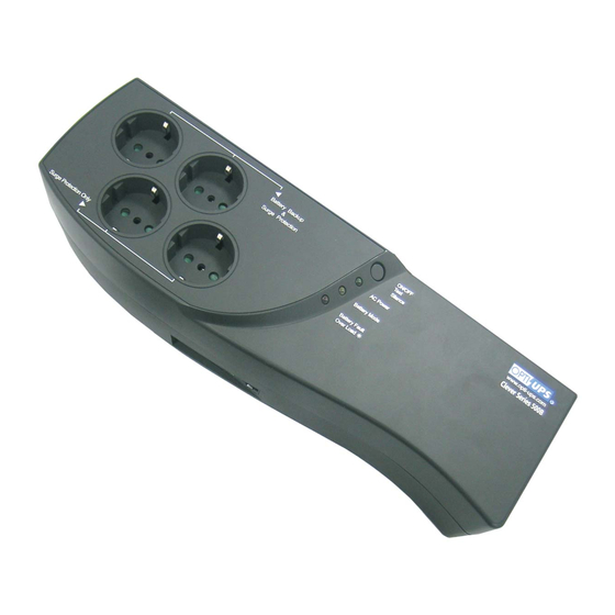
CS500B
User Manual
Data Line Surge Protection
CS500B's exclusive communication protection ports will protect
any standard modem, PBX System or 10/100 BaseT connection
ports. This communication port can accommodate either the
phone (RJ-11) or network (RJ-45) jack.
USB Port of
TEL / FAX /
Computer
Modem / LAN
LED Indicators & Alarms
Battery
Fault/
Over
Load
AC mode
Green LED ON
Red LED flashes once
Battery fault
every 0.5 sec
Overload
Red LED ON
Backup
Yellow LED flashes
mode
once every 4 sec
Yellow LED flashes
Battery low
once every 1 sec
Charger
Green LED ON
abnormal
Placement
CS500B is intended for indoor use
only; its internal components are not
sealed from the environment.
Please install CS500B in a protected
environment away from excessive heat
or excessive moisture.
Charging the UPS first
The battery is fully charged at the
factory. However, user is recommended
to charge the battery at least 4 (FOUR)
hours before using UPS, since energy
loss
may
have
occurred
during
shipping or long duration storage. To
recharge the battery, simply let UPS be
plugged into an AC outlet.
USB Communication Port
Please link CS500B USB port with computer USB
port using the USB cable which is attached inside the
box. Now, you can use the software (OPTI-SAFE
SENTINEL) to control your computer and CS500B.
Install Software
Make sure your communication cable is connected to
your UPS as shown in the left picture.
To install the software, follow the steps below.
Simply insert software CD into your computer, and
the install process will begin. If not, run Setup.exe
from the CD manually.
Wall Jack
Battery
AC mode
Backup
None
None
ON
Buzzes once every 4 sec
Buzzes once every 1 sec
Buzzes once every 0.5 sec
Connect Equipment to CS500B
Battery Backup & Surge Protection Outlets
These two outlets not only provide surge protection but also backup power for your
equipment. In case of AC failure, battery power is automatically provided to two three
outlets. Please connect your main devices to these outlets.
Surge Protection Outlets
These two outlets provide surge protection but do not provide power during AC failure.
Turn on the UPS
The UPS can be turned on after connecting to the utility power. After the UPS is turned
on, it conducts a self-test and enters normal mode. Pressing the power button for 1 second
under normal mode will also enable the self-test function. The silence function can be
enabled/disabled by pressing the power button for 1 second in backup mode. In addition,
the power button can be used as the master on/off switch for your equipment by leaving
your equipment connected to UPS and switched on. To turn off the UPS, please press
power button until buzzer stops (about 2 seconds).
Battery Replacement Procedure
Note: Follow this procedure for safe replacement of the battery. However, small sparks may occur
during the process. This is normal.
1.
Remove the two screws on the
bottom of UPS
.
4.
Connect the wires to the new battery making sure that the red wire is connected to the red battery
terminal and the black wire is connected to the black battery terminal.
1.
5. Reverse the procedure from 3 to
Circuit Breaker
The circuit breaker button is located at the side
of CS500B. It will stick out to disconnect itself
from the utility power when an overload
condition occurs. If the button sticks out,
disconnect nonessential equipment. Reset the
circuit breaker by pushing the button inward.
Circuit Breaker
2.
Pull and open the battery cover.
3.
Pull out the battery and disconnect the
two wires connecting the battery to
the UPS.
ON/OFF
Test
Silence
Advertisement
Table of Contents

Subscribe to Our Youtube Channel
Related Manuals for OPTI-UPS CS500B


Summary of Contents for OPTI-UPS CS500B
- Page 1 PBX System or 10/100 BaseT connection port using the USB cable which is attached inside the of CS500B. It will stick out to disconnect itself ports. This communication port can accommodate either the box. Now, you can use the software (OPTI-SAFE from the utility power when an overload phone (RJ-11) or network (RJ-45) jack.
-
Page 2: Specifications
For accurate warranty period and conditions, please contact local branch offices or your dealers. CS500B can be mounted to a wall surface. Please see the illustration below. Who the warranty protects: There are two key-hole slots on the bottom of the UPS.
Need help?
Do you have a question about the CS500B and is the answer not in the manual?
Questions and answers