Advertisement
Quick Links
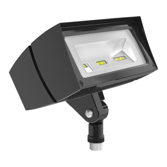
FFLED18 INSTALLATION INSTRUCTIONS
Thank you for buying RAB lighting fi xtures. Our goal is to design the best quality products to get the job done right. We'd like to hear your comments.
Call the Marketing Department at 888-RAB-1000, or email: marketing@rabweb.com
IMPORTANT
READ CAREFULLY BEFORE INSTALLING FIXTURE. RETAIN THESE INSTRUCTIONS FOR FUTURE REFERENCE.
RAB fi xtures must be wired in accordance with the National Electrical Code and all applicable local codes. Proper
grounding is required for safety. THIS PRODUCT MUST BE INSTALLED IN ACCORDANCE WITH THE APPLICABLE
INSTALLATION CODE BY A PERSON FAMILIAR WITH THE CONSTRUCTION AND OPERATION OF THE PRODUCT
AND THE HAZARDS INVOLVED.
WARNING: Make certain power is OFF before installing or maintaining fi xture. No user serviceable
parts inside.
LOCATION
1. Seal arm thread using tefl on tape or silicone sealant.
2. Secure the LED Flood to a 1/2" NPS hole in a
junction box or landscape post.
3. Plug all unused holes and seal threads with silicone.
4. The swivel arm on the LED Flood allows 140º - 150º
of vertical aiming adjustment depending on mounting
location.
WIRING
Universal voltage drivers permit operation at 120V to
277VAC, 50 or 60 Hz except fi xtures factory ordered
with a 120V photocell (/PC)
1. Connect the BLACK fi xture lead to the
(+) LINE supply lead.
2. Connect the WHITE fi xture lead to the
(-) COMMON supply lead.
3. Connect the bare copper Ground wire from fi xture
to supply ground.
GUARD or SHIELD INSTALLATION
Wire Guard and Poly Shield mount with (4) #8-32
Stainless Steel Screws. Screws are provided with
accessory. See fi gure 1 for Guard. See fi gure 2
for Shield
1. Line up guard with pre-existing, pre-drilled holes in
frame as shown, tighten screws.
Figure 1
Figure 2
GUARD & SHIELD INSTALLATION
The Wire Guard and Poly Shield can be mounted on the
same fi xture with (4) #8-32 screws as shown below.
Stainless
Steel Screws
Stainless
Steel Screws
Advertisement

Related Manuals for RAB Lighting Mini Sensor


Summary of Contents for RAB Lighting Mini Sensor
- Page 1 FFLED18 INSTALLATION INSTRUCTIONS Thank you for buying RAB lighting fi xtures. Our goal is to design the best quality products to get the job done right. We’d like to hear your comments. Call the Marketing Department at 888-RAB-1000, or email: marketing@rabweb.com IMPORTANT READ CAREFULLY BEFORE INSTALLING FIXTURE.
-
Page 2: Troubleshooting
FFLED18 INSTALLATION INSTRUCTIONS TROUBLESHOOTING CLEANING & MAINTENANCE CAUTION: Be sure fi xture temperature is cool enough to touch. Do not clean or maintain while 1. Check that the line voltage at the fi xture is correct. fi xture is energized. Refer to wiring directions. -
Page 3: Installation Manual
Mini Sensor Contents Outdoor Motion Sensor Installation Manual Specifications Switching Capacity: Built for Severe Conditions: Double weatherproofing for long life. Relay On/Off Model: 500 watts Incandescent or Photoelectric Control: 250 watts Fluorescent @ 120 volts Deactivates lights during daylight. Fully adjustable for 24 hour Hi/Lo Model: operation or custom applications. - Page 4 • Sensor functions best when movement is across its detection pattern, not towards the sensor. Molded is better! No leaky gaskets or bug hotels with Mini Sensor. The hard lens is molded as part of the case. It’s vandalproof, rainproof, bugproof and absolutely sealed.
- Page 5 Assembly and Wiring Wiring Diagrams To override 1. Screw the threaded arm of the sen- Basic Wiring Diagram sensor with a sor into the center hole of the mounting manual switch Black Black plate. Sensors can be wall or ceiling White mounted.
- Page 6 Detection Zone and and close range. Zone is vacated from approximately turns on lights automatically. It • Mini Sensor may be wall or ceiling 5 seconds to 15 minutes. Use the welcomes visitors and may deter mounted.
- Page 7 Photocell Control is turned to the be enough. while at 30 feet, several sun symbol, the lights will stay on in 3. Make sure that Mini Sensor is not Photocell steps will be necessary. low mode in low level light and night.
- Page 8 Technical Tips: Lights Turn Off Technical Tips: Lights Do Not Turn On Range appears limited Too Quickly 4. Check that movement is not direct- 1. Check that the sensor is level from 1. Check if sensor is being “tricked” 1. Check that lamps and fixtures ly towards sensor.
- Page 9 Technical Tips: Technical Tips: Lights Turn On For Unknown Reasons Lights Turn On and Off Incorrectly 5. Make sure lights are not visible 1. Lights may turn on occassionally 1. Make sure the sensor is installed from or reflecting back into sensor. on its own dedicated circuit free of during rain, snow and windstorms Check for white or reflective surfaces...
- Page 10 Limited Warranty Toll Free Technical Assistance Your Mini Sensor will be promptly If you need technical assistance, replaced or repaired, at our option, if please do the following: it proves to be defective in workman- ship or materials within 5 years of 1.
Need help?
Do you have a question about the Mini Sensor and is the answer not in the manual?
Questions and answers