Table of Contents
Advertisement
Quick Links
Advertisement
Table of Contents

Related Manuals for Digital Watchdog Vmax960-8


Summary of Contents for Digital Watchdog Vmax960-8
-
Page 2: Safety Information
1 | H.264 Digital Video Recorder Safety Information The safety information is provided for the wellness of the equipment and for the safety of the operator. Please review and observe all instructions and warnings in this manual. Note : Keep this manual handy every time you operate this equipment. Also, check with your dealer for further assistance and for the latest revision of this manual. -
Page 3: Table Of Contents
User’s Manual | 2 Contents 1 : DVR U HAPTER ANUAL ETTING TARTED 1.1 Checking Supplied Items 1.2 Connecting Peripheral Device 1.3 System Startup and Shutdown XPLANATION FOR UNCTION 2.1 Front Panel 2.2 Rear Panel 2.3 IR Remote Controller PERATION 3.1 User Log-in 3.2 Quick Startup Wizard 3.3 Live Display Mode... - Page 4 3 | H.264 Digital Video Recorder 2 : CMS C HAPTER LIENT OFTWARE ANUAL 6 CMS U UIDE 6.1 PC REQUIREMENT 6.2 INSTALL 6.3 UNINSTALL 6.4 BASIC OPERATION 6.5 CMS FUNCTIONS 6.6 CMS SETUP 3 : ACS C HAPTER LIENT OFTWARE ANUAL 7 ACS U...
- Page 5 User’s Manual | 4 6 : M HAPTER OBILE HONE OFTWARE ANUAL 10 M OBILE HONE OFTWARE UIDE 10.1 iPhone application software 10.2 Android application software 10.3 Using WAP+3G Connection DNS S PPENDIX EGISTRATION PPENDIX ETWORK ETUP FOR XTERNAL SAGE PPENDIX PECIFICATION...
- Page 6 5 | H.264 Digital Video Recorder...
-
Page 7: Dvr User Manual
User’s Manual | 6 Chapter 1 DVR U ANUAL... - Page 8 7 | Chapter 1 : DVR User Manual...
-
Page 9: Getting Started
User’s Manual | 8 ETTING TARTED 1.1 Checking Supplied Items Make sure that you have the following items supplied with your DVR. If any of these items are missing or damaged, notify your vendor immediately. Keep the packing utilities for moving or storage purposes afterwards. Items Photo Quantity... -
Page 10: Connecting Peripheral Device
9 | Chapter 1 : DVR User Manual 1.2 Connecting Peripheral Device This section describes how to connect peripheral devices efficiently to the DVR. Install the DVR on flat surface. If required, attach a rubber mount for installation. If a 19-inch rack is used with 1.5U Height case, it is recommend to install the system on a shelf and use 2.5~3U (1U=1.75 inch or 4.45 cm) space for proper ventilation. -
Page 11: System Startup And Shutdown
User’s Manual | 10 1.3 System Startup and Shutdown 1.3.1 System Startup After connecting peripheral devices such as cameras, monitors and a mouse to the DVR, power up the DVR by connecting DC12V 9A adaptor to the power jack on the rear panel. The boot log will display as shown below. Please wait until the boot process completes. - Page 12 11 | Chapter 1 : DVR User Manual 1.3.2 System Shutdown and change password Option 1. Click the Shutdown button and input password on pop-up to power off the DVR Option 2. Click the right button on the mouse and select the Shut Down to power off the DVR. It is not recommended to disconnect the power cable abruptly from the back of the DVR because it may affect the DVR and Hard Drive.
-
Page 13: Explanation For Each Function
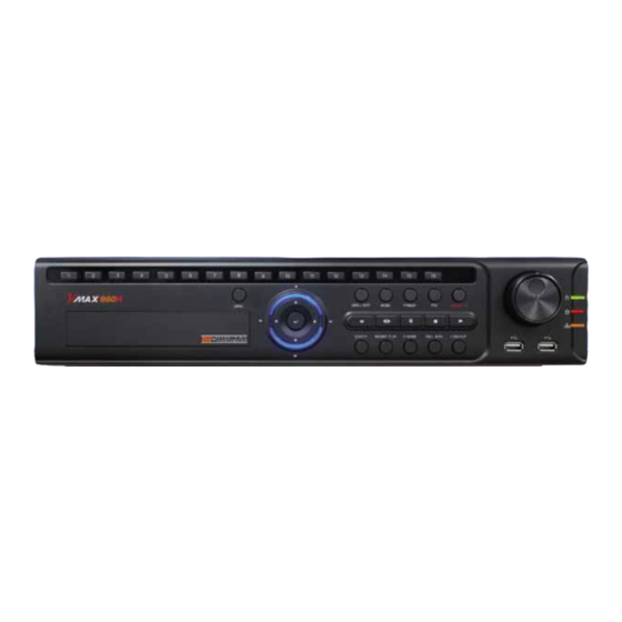
User’s Manual | 12 XPLANATION FOR UNCTION 2.1 Front Panel [8/16CH (W)428x(H)93x(D)446mm] Buttons Functions Menu / Exit Menu / Exit toggled button Mode Change screen display mode Freeze Freeze display screen on/off PTZ control on/off Instant Record Button Emergency Recording Search Go to search mode Instant Play... -
Page 14: Rear Panel
13 | Chapter 1 : DVR User Manual 2.2 Rear Panel [8CH (W)428x(H)93x(D)446mm] [16CH (W)428x(H)93x(D)446mm] Functions VIDEO-IN Camera Input from CH1 upto CH16 (Auto-detect NTSC/PAL) LOOP OUT Loops through output from CH1 upto CH16 VIDEO OUT Main output in composite SPOT OUT Programmable digital spot outputu e-SATA... -
Page 15: Ir Remote Controller
User’s Manual | 14 2.3 IR Remote Controller In order to use IR Remote Controller, the ID of the IR Remote Controller must be same as the ID of the DVR. (Default ID # for DVR and IR Remote Controller is “1”.) If you have more than two DVRs, you are able to control them individually with just one remote controller by setting up ‘Remote ID’. -
Page 16: Operation
15 | Chapter 1 : DVR User Manual PERATION 3.1 User Log-in The DVR has various setting categories. The administrator can set the system password and <User> to prevent unauthorized changes to setting values and alteration of recorded file. Enter the <Admin> or <User> password which had been set by using the virtual keyboard. 1) <LOGIN>... -
Page 17: Quick Startup Wizard
User’s Manual | 16 3.2 Quick Startup Wizard Quick Startup Wizard is specially designed to make it much easier for the major DVR settings such as Time/Date setup, Record setup, Network setup and Quick setup. When the DVR boots up, the Quick Startup Wizard operates automatically. It can be disabled by setting in the main menu. -
Page 18: Live Display Mode
17 | Chapter 1 : DVR User Manual 3.3 Live Display Mode 3.3.1 Full HD(1080p) Live Display Full HD Live Display can is available in live quad (4) mode by using its HDMI and VGA output. In playback mode, the maximum resolution is 960x480 / 960x576(NTSC/PAL). <Full HD Live Display>... -
Page 19: Channel Selection
User’s Manual | 18 3.3.3 Channel Selection Channel selction can be done by following one of the steps below: CH1~CH16 buttons loicatd on the top of the front panel. 1~16 buttons on the IR Remote Control. The display mode can be changed by pressing the ‘MODE’ button on the DVR’s front panel. The live images can be displayed in real-time in 1, 4, 9, 16 screen splits. - Page 20 19 | Chapter 1 : DVR User Manual 3.3.4 Icons The live mode display’s icons or messages will be indicated on the screen to indicate the system mode or status. Below are the icon categories that are indicated on the monitor. Icon to be shown Icon to be shown at Left-upper corner on each channel screen...
- Page 21 User’s Manual | 20 3.3.5 Pop-up Menu Right-clicking anywhere on the screen will open up the pop up sub-menu as shown below: DISPLAY- Select the display split from the available options: - 1 Screen- Single channel. Automatically displays CH1. If 1 Screen is selected again, next chronological channel will be displayed.
- Page 22 21 | Chapter 1 : DVR User Manual SHUT DOWN- Power off the DVR. LOGOUT- User logout. When a camera is disconnected, a warning sound may be generated depending on the system settings. As the Admin user, you can seup up multiple users with different levels of authorization. If a certain user is not allowed to view a certain camera in live or playback, then no image will appear on the display screen.
-
Page 23: Ptz Operation
User’s Manual | 22 3.4 PTZ Operation Before starting PTZ control, please make sure the camera you wish to control is a supported PTZ camera and is installed and configured properly. See section 4.2.6 PTZ for setup information. To enter PTZ mode, follow one of the options below: Right-click on the screen and select PTZ Control. -
Page 24: Freeze Mode
23 | Chapter 1 : DVR User Manual User can automatically switch PTZ camera positions according to defined presets by using the GUARD TOUR function. The connected PTZ camera must support touring functions. “GUARD TOUR” on the pop-up menu can be enabled only in full screen mode. -
Page 25: Call Monitor Operation
User’s Manual | 24 3.6 Call Monitor Operation Press the CALL MON button on the front panel, or click the right button on the mouse and select the CALL MONITOR in order to enter call monitor control mode. The numeric panel will pop up at the center of the screen. Click the specific channel button on the numeric panel to display full screen mode out of assigned spot out channels. - Page 26 25 | Chapter 1 : DVR User Manual In playback screen, user can make various playback modes, make an instant manual backup (archive), go to calendar search mode, change channel, and change screen modes. By clicking the left mouse button in the colored-time bar, the user can jump to a different time in the recording.
-
Page 27: Single Channel Playback In Live Mode (Cameo)
User’s Manual | 26 3.8 Single Channel Playback in Live Mode (Cameo) Single channel playback can be displayed while other channels are still in live mode. In live view mode, right-click on the channel that you want to view in playback and select Search Single Channel Search. -
Page 28: Quick Backup During Playback
27 | Chapter 1 : DVR User Manual 3.9 Quick Backup during Playback User can easily archive video while viewing the video during live or playback mode. In playback mode, press and hold the “I.BACKUP” button on the front panel to set start time for the backup video. -
Page 29: Search Recording Image
User’s Manual | 28 3.10 Search Recording Image 3.10.1 Date/Time Search To search your recorded data by date/ time, follow one of the options below: Click the quick Menu button at the left side of the menu bar, select Search Date/ Time Right-click anywhere on the screen, select Search Date/ Time... -
Page 30: Event Log
29 | Chapter 1 : DVR User Manual triggered during dwell time. The system will also send a “sensor event” message to the Pivot Client Software over the network. If “SENSOR” is disabled in the “DEVICE” menu, and recording mdoe is set to “CONT + SENS”, the system will record with continuous recording even when a sensor is triggered. -
Page 31: System Log
User’s Manual | 30 3.10.3 System Log The system log search allows you to search for any changes made to the system, quickly and easily, displaying the search results in a detailed table format. To open System Log Search, perform one of the following options: Click quick menu button, select Search System Log... -
Page 32: First Data
31 | Chapter 1 : DVR User Manual 9 numbers of log record will be shown on one page of the <System Log> and <Event Log> window. User can click the arrow icon to search the log records on another page. 3.10.4 First Data Go to the first screen of the recorded video. -
Page 33: Dst Setting
User’s Manual | 32 3.11 DST Setting DST starts at 2:00 local time on 2 Sunday of March, and ends at 2:00 DST on 1 Sunday of November. During DST (Daylight Saving Time) period, DVR time clock has to be adjusted according to regional time zone. That is, the DVR time clock will be shifted by one hour after the DST settings start, and the DVR will restore the time clock back to normal after DST finishes. -
Page 34: Screen Saver
33 | Chapter 1 : DVR User Manual When user click on such overlapped period, a message titled “Recorded video Selection” will pop up. The user can then select whether to play DST data or Non-DST data. Click OK to play DST image. Click CANCEL to play Non-DST image. -
Page 35: Setting
User’s Manual | 34 ETTING General setting structure consists of “System”, “Device”, “Record”, “Network”, “Backup,” and ‘Quick Setup” as shown <SYSTEM> <DEVICE> <RECORD> <NETWORK> <BACKUP> <Q-SETUP> Main Classification Sub Classification SYSTEM INFO USER EXPORT/IMPORT SYSTEM FACTORY DEFAULT FACE STAMP CAMERA AUDIO SENSOR DEVICE... -
Page 36: System
35 | Chapter 1 : DVR User Manual 4.1 System The system menu button is selected by clicking “TOOL” on the menu bar or clicking the right mouse button. Users can move mouse pointer from “System” through “Quick Setup” to instantly look around the sub-menus on the menu screen. - Page 37 Click “OK” to confirm. Upgrading system using Digital Watchdog’s FTP server: Select FTP in the drop-down list and type a given IP address in the Host Address (Digital Watchdog’s FTP Server IP Address: 208.179.32.42). Username and password is “none” (Default).
- Page 38 37 | Chapter 1 : DVR User Manual NTP Setup- Setup the DVR to automatically sync with a Network Time Protocol. There are two types of TIME SYNC MODE: Server Mode- The DVR is set as a Time Sync Server, which can synchronize its own time with another DVR(s) connected over the same network environment.
- Page 39 User’s Manual | 38 4.1.2 User Master user of this system is always Admin with factory default of No password. This user cannot be deleted. It is recommended that the Admin change the password for extra security. Admin can designate a new user with different permission levels by: functions, menu access, and live & playback. “Function”...
- Page 40 39 | Chapter 1 : DVR User Manual 4.1.3 Export/Import Users can copy and paste the system configuration values in this menu. “Export” allows the user to copy the settings for this system to USB memory devices. “Import” allows the user to recall the settings saved from other systems using USB memory devices.
-
Page 41: Factory Default
4.1.6 Face Stamp Set-up The Facestamp is an exclusive Digital Watchdog feature used for employee and time amangement. It is compatible only with Digital Watchdog’s VMAX960H series. If you have purchased the Facestamp hardware, follow the instructions below on setting up the Facestamp on the DVR. - Page 42 41 | Chapter 1 : DVR User Manual 4.1.7 Face Stamp User Registration Listed users can be monitored as Faces Stamp events through VMAX960H & VMAX960H Flex when listed users check in and out Face Stamp. To add, delete, or modifty Facestamp users, go to the DVR’s System Settings, Facestamp sub-menu. 1.
- Page 43 User’s Manual | 42 4.1.9 Face Stamp Search Whenever users check in our out using the Face Stamp access panel, the check in or out will be recorded as an event, and a picture of the user will be stored in the DVR. Managers then can search and review their employee’s time and attendance. To perform a local search on the DVR for all Facestamp events follow these steps: 1.
-
Page 44: Device
43 | Chapter 1 : DVR User Manual 4.2 Device There are Seven sub menus in the Device menu, such as Camera, Audio, Sensor, Motion Alarm, Extra Alarm, and PTZ. Users can easily move to the “Device” menu by selecting the icon on the top right of the menu screen. - Page 45 User’s Manual | 44 4.2.2 Audio Users can select the audio input and output during live display and match the audio input to a designated channel. (Please refer to Section 4.3.1 Camera Record). Adjust the audio volume using the volume control panel, enable or disable audio recording for each channel, and enable or disable audio during live video.
- Page 46 45 | Chapter 1 : DVR User Manual Preset- User can select the camera to move to a preset position, once the sensor is triggered. (User should setup preset position in PTZ menu 4.2.6 in advance) In addition, users can set multi-preset with a single PTZ camera. Therefore, users can cover a multi-preset zone with a single PTZ camera.
-
Page 47: Motion Alarm
User’s Manual | 46 4.2.4 Motion Alarm Select Motion alarm to record only when motion detection is triggered by DVR S/W upon user’s defined motion area. An alarm signal is sent via the selected sensor-out channel. COPY SETTINGS- Upon pressing Copy Settings button, Copy Settings popup will appear. In this popup, choose the camera the user wants to copy from at the “From”... - Page 48 47 | Chapter 1 : DVR User Manual 4.2.6 PTZ Full control of PTZ camera is available in this menu. For details, please refer to Section 3.4 PTZ Operation. Protocol- Select the proper protocol of the connected PTZ camera. Address- Set the PTZ driver address of the connected camera. Check the below items for proper P/T/Z operation.
-
Page 49: Record
User’s Manual | 48 4.3 Record Users can configure various record settings such as Continuous, Event, and Panic for each individual camera in the Record Setup Menu. Network Stream settings are independently configured from the Record settings in this menu as well. Use this setup option to ptimize the bandwidth used by the DVR by configuring the resolution, FPS, and image quality separately. - Page 50 49 | Chapter 1 : DVR User Manual Users can also configure the Network Stream settings independently from the Record settings under the “Live Stream” tab as shown below. The Live Stream menu enables users to optimize data transmitted over the network by configuring the Resolution, FPS, and Quality without affecting the Record settings.
- Page 51 User’s Manual | 50 4.3.2 Schedule You can set up the record schedule by applying a various record modes to each date and time. Simply select a record mode by mouse and drag it to the desired date and time. 4.3.3 Holiday Users can setup a specific day of a month or day of week as a holiday as shown below.
-
Page 52: Network
51 | Chapter 1 : DVR User Manual 4.4 Network 4.4.1 Network The system has built-in web server. ETHERNET - DVR network system - ETHERNET LAN port Network Type Select network connect type. Select either LAN for fixed (Static) IP or DHCP for dynamic IP. If DHCP is selected, click ‘IP DETECT’... - Page 53 User’s Manual | 52 UPnP (Universal Plug and Play) and Auto Private IP Setup (NAT Traversal) UPnP stands for Universal Plug and Play, which is a relatively new technology that indicates a universal protocol for widespread plug-and-play devices to ease the network implementation. When a PC and a DVR both installed the UPnP function, the PC can automatically recognize the DVR in the same local area network.
- Page 54 53 | Chapter 1 : DVR User Manual 4.4.2 DDNS The User has to mark the “Use DDNS” check box to use it. DDNS Server dwddns.net or dwddns2.net is the fixed domain name of DDNS server. User cannot change the DDNS name. The standard DDNS domain name is dwddns2.net, and users can use dwddns.net or dyndns.com by drop-down list.
- Page 55 User’s Manual | 54 4.4.3 Notification Remote Notify The system can notify an alarm message to the IP address of Advanced Client Software over the network. User can choose from a selection of different kinds of alarms by pressing “ADD.” Alarms can be generated by Sensor, Motion Detection, Disk Full, Admin PW Changed, Video Loss, and Power On/Off.
-
Page 56: Health Check
55 | Chapter 1 : DVR User Manual 4.4.4 Health Check The VMAX960H offers a uniquely true DVR health monitoring, with pop-up messages and e-mail notification on video loss, recording failure, and storage failure. To setup: 1. Check the box next to "Enable Health Check" 2. -
Page 57: Backup
User’s Manual | 56 4.5 Backup 4.5.1 Backup Users can archive a video clip recorded for a certain period on a selected channel or channels as shown below. Connect an appropriate USB memory device, like USB thumb drive, USB HDD, or a built-in CD or DVD burner and press “SCAN”... - Page 58 57 | Chapter 1 : DVR User Manual 4.5.2 Backup Video Retrieve There will be a single file after archiving, if “Auto Player” was selected. User can double click “BackupPlayer.exe” file to open the video data file (PSF format) in the folder. User can print out, capture a still image, zoom out, or make an ASF file format, by using the icons located on top of the player window.
-
Page 59: Quick Setup
User’s Manual | 58 4.6 Quick Setup Quick Setup helps user make simple configuration for recording resolution, entire recording speed by frame, recording mode, and recording periods. The system will put the first priority for configuration on this quick setup and will follow this rule regardless of configurations set in other menus. -
Page 60: Web Surveillance
59 | Chapter 1 : DVR User Manual URVEILLANCE The VMAX960H DVR has a built-in web server. Using an ordinary web-browser over a network, users can always stay connected to the system for live monitoring, playback, or remote configuration without installing any remote client software. 5.1 Web Login The user is required to input the correct IP address in the web browser after making the web port available in the router. -
Page 61: Web Configuration
User’s Manual | 60 5.2 Web Configuration Menu of Web Configuration Main Classification Sub Classification SYSTEM INFO USER SYSTEM DEFAULT CAMERA AUDIO DEVICE SENSOR MOTION ALARM EXTRA ALARM RECORD SETUP LIVE STREAM RECORD PANIC RECORD SCHEDULE NETWORK NETWORK DDNS NOTIFICATION QUICK SETUP QUICK SETUP After logging in with the right ID and password, users can make various configuration changes in the Web Configuration... - Page 62 61 | Chapter 1 : DVR User Manual [Record] [Network] [Quick Setup] This web CGI screen is directly supported from the built-in web server in the DVR, regardless of Internet connection. <System Reboot> enables user to reboot the system without any changes to the setup. When the network is disconnected due to abnormal operation of the system, user can use this function and try to reconnect.
-
Page 63: Web Monitoring
User’s Manual | 62 5.3 Web monitoring The first time you access your DVR via the Web viewer, you will be asked to install Active-X file before monitoring live video. Please follow the installation process to complete the Active-X installation. Without it, you will not be able to view video from any of the DVR’s channels. - Page 64 63 | Chapter 1 : DVR User Manual Title Function Connection Mode Select to view the DVR in Live or Playback Mode. Connection Option Select to Connect or Disconnect from the DVR. PTZ control options, including: virtual direction arrows, zoom and focus, and preset.
- Page 65 User’s Manual | 64 User can monitor live video in 1, 4, 9 or 16 screen modes. If user wants to see single channel in full screen, double-click on the live video screen. User can change to single mode by clicking the mode icon located at the bottom left. The image resolution in “Live monitoring”...
-
Page 66: Web Playback
65 | Chapter 1 : DVR User Manual 5.4 Web Playback Users can remotely playback the DVR images by clicking “SEARCH” button in the middle of bottom window. In order to connect to DVR, the user has to click “ Connect ” button which is located at the top left corner. Playback Time Select the date and time on Time Search, located at the middle of left side of window, and click button. - Page 67 User’s Manual | 66 Chapter 2 CMS C LIENT OFTWARE ANUAL...
- Page 68 67 | Chapter 2 : CMS Client Software User Manual...
-
Page 69: Pc Requirement
User’s Manual | 68 6 CMS U UIDE 6.1 PC REQUIREMENT Recommended PC Requirement Windows XP, Vista, 7 Pentium Dual core 1.8Ghz or higher 1024X768, 256MB supporting DirectX 20MB for installation, 10GB for Remote Backup Minimum PC Requirement Windows XP, Vista Pentium 4, 2Ghz 1024X768, 64MB 24bit color graphic card 20MB Free Space... - Page 70 69 | Chapter 2 : CMS Client Software User Manual Press to move to the next screen. Press to move to the next screen. Select what Icons and shortcuts you wish to install on your desktop. Press to move to the next screen.
-
Page 71: Uninstall
User’s Manual | 70 Select to begin installation. When the installation is complete, the below message will appear. Select whether you want to launch the software and select “finish”. 6.3 UNINSTALL To uninstall CMS, press UNINSTALL CMS from the Start Menu of your PC. A window will appear in Windows7 or Windows Vista. -
Page 72: Basic Operation
71 | Chapter 2 : CMS Client Software User Manual When the process is complete, the below message will appear. 6.4 BASIC OPERATION Click on the CMS icon on the Desktop or click START on Windows PC and go to the CMS Folder. -
Page 73: Screen Layout
User’s Manual | 72 6.4.1 LOG IN The default ID is Administrator, and there is no default password. The administrator account has the highest level of authority on the CMS. 6.4.2 SCREEN LAYOUT... - Page 74 73 | Chapter 2 : CMS Client Software User Manual Item Description Main Toolbar The Main Toolbar has three (3) selectable tabs named "Main", "Export" and (Setup Tab) "Setup". In the Setup tab, there are CMS setup and Remote setup. Main Toolbar In the Export tab, users can save JPEG, AVI and Print images of selected (Export Tab)
- Page 75 User’s Manual | 74 6.4.4 MAIN TOOLBAR (EXPORT) Item Description Image Capture an image of the selected (focused) channel. Movie Save the selected channel in ASF format movie file. Print Print the selected channel. 6.4.5 MAIN TOOLBAR (MAIN) Item Description Live Connect to the selected site in Live mode.
-
Page 76: Site List
75 | Chapter 2 : CMS Client Software User Manual 6.4.6 SITE LIST The Site List displays all of the DEVICES that are currently setup for remote connection with the CMS application. To select and view a desired camera or device, simply drag it from the site list panel onto the viewing area. Then, select the options Live or Search ( If a DEVICE site is dragged onto the viewable area, then the selected DEVICE or all cameras from the DEVICE will be displayed. - Page 77 User’s Manual | 76 Button Description 8 directional arrows allow the user to move the PTZ camera. The PTZ Camera is Navigation moved when one of these arrows are pressed to the direction desired, and stops the movement if the mouse button is released. Zoom Zoom In and Zoom Out.
- Page 78 77 | Chapter 2 : CMS Client Software User Manual Click the time or move the time bar to the time you want to playback in the search panel. For a more detailed search as seen below, double-click the time that you want to jump. Detailed search is available on a 6 minute basis as shown below.
-
Page 79: Event Search
User’s Manual | 78 6.4.10 DISPLAY In live mode, the text LIVE will be displayed in white, and the channel will be bordered in blue. In search mode, the text SEARCH will be displayed in red, and the channel will be bordered in red. A selected channel will be bordered in yellow. - Page 80 79 | Chapter 2 : CMS Client Software User Manual 6.4.12 INFORMATION The current date/time, site name, IP address, ID, channel and Live/Search status will be shown for a selected channel. 6.4.13 FAVORITE Cameras currently displayed on the screen can be added, deleted and edited as a favorite site group.
-
Page 81: Cms Functions
User’s Manual | 80 6.5 CMS FUNCTIONS 6.5.1 EVENT SEARCH When you right click on a site in the site list, a quick access menu will appear. Select EVENT SEARCH to run Event Search. Item Description The information of the DEVICE you are connected to will be filled out System Connection Info automatically. -
Page 82: Remote Backup
81 | Chapter 2 : CMS Client Software User Manual 6.5.2 REMOTE BACKUP When you right click on a site in the site list, the quick access menu will appear. Select REMOTE BACKUP to run Remote Backup. Item Description The information of the DEVICE you are connected to will be filled out System Connection Info automatically. -
Page 83: Firmware Upgrade
User’s Manual | 82 6.5.3 FIRMWARE UPGRADE When you right click on a site in the site list, the quick access menu will appear. Select FIRMWARE UPGRADE to run Firmware Upgrade. Description Item DEVICE Connection Info Input the information of DEVICE you are connected to. Firmware File Directory Select the firmware file directory to upgrade. - Page 84 83 | Chapter 2 : CMS Client Software User Manual 6.5.4 MULTI MONITOR Click MULTI MONITOR in the Main Toolbar to run the Multi Monitor function. When you select MULTI MONITOR, you will see an additional window with the same split display as the main window. This setup is useful if your monitor center has more than one monitor screen.
-
Page 85: Thumbnail Search
User’s Manual | 84 6.5.6 THUMBNAIL SEARCH Click THUMBNAIL in the main toolbar to run the Thumbnail Search. This feature is available only in Search mode. First, select a channel and click THUMBNAIL. The Thumbnail Search Pop-up window will come up. Item Description Date... - Page 86 85 | Chapter 2 : CMS Client Software User Manual 6.5.7 BOOKMARK Click icon in the bottom right corner under the video display screen to bookmark a selected one channel search data. Once the selected search data is bookmarked, the bookmark data is listed with an image in the bookmark list as shown below. Select a bookmark list and click search or double click it to search the bookmarked data.
-
Page 87: Cms Setup
User’s Manual | 86 6.5.9 DIGITAL ZOOM IN/OUT In Live/Search mode, digital zoom can be activated in a single full screen mode by using the mouse wheel. Scroll up the mouse wheel, to zoom in. Scroll down the mouse wheel to zoom out on selected channel. 6.6 CMS SETUP Options for DEVICE Registration, Network, User, Display, Event and other options. - Page 88 87 | Chapter 2 : CMS Client Software User Manual Item Description Name The name of the site. The site’s IP Address. Search Search all DEVICE sites in the same local network. (UPnP function) Port Port of the site. (Default: 9010) Web port Web Port of the site.
-
Page 89: Adding Ip Cameras
4. Select which camera you want to add and click ok. Review any of the network settings if necessary and click ok to add the camera. 5. If you are adding a Digital Watchdog MEGApix camera manually under ONVIF: a. Enter the IP address as follows: rtsp://ipaddress:554/h264 (for example: rtsp://72.243.193.200:554/h264) b. - Page 90 89 | Chapter 2 : CMS Client Software User Manual 6.6.4 NETWORK Enables users to setup RECONNECT and AUTO CONNECT to the network. Enable Reconnect: When the network is unstable or disconnected, it will try to reconnect periodically. When the network gets stable again, it’s reconnected.
- Page 91 User’s Manual | 90 6.6.6 DISPLAY Options for OSD setting. Users can modify what information will be displayed on the video screens. Title: Turn on/off the DEVICE title and channel number. Date/Time: Turn on/off the Date/Time of the site. DEVICE Name: Turn on/off the name of the site. Time Format Sync: Synchronize the DEVICE time format to CMS.
- Page 92 91 | Chapter 2 : CMS Client Software User Manual 6.6.2 MISC. Setup the Recording Directory, Language, Auto Upgrade, and Auto Login. Item Description Recording Directory Decide the recording directory to save images. Language Select a desired language. In order to have Auto Upgrade, input FTP information. Once the FTP setup is FTP Information done, CMS will detect the latest firmware is in the FTP and start upgrading automatically.
- Page 93 92 | H.264 Digital Video Recorder Chapter 3 ACS C LIENT OFTWARE ANUAL...
- Page 94 93 | Chapter 3 : ACS Client Software User Manual...
-
Page 95: System Requirement
User’s Manual | 94 7 ACS U UIDE 7.1 System Requirement Recommended System Requirement WindowXP, Vista Pentium 4, 2Ghz 1024*768, 64MB 24bit color graphic card 20MB Free space Minimum System Requirement. WindowXP, Vista Intel Core i5 cpu 2.80GHz ATI Radeon HD 512 20MB Free space 7.2 Install Run Advanced Client SoftwareSetup.exe on the included CD. - Page 96 95 | Chapter 3 : ACS Client Software User Manual Select what Icons and shortcuts you wish to install on your desktop. Press to move to the next screen Select to begin installation. When the installation is complete, the below message will appear. Select whether you want to launch the software and select “finish”.
-
Page 97: Uninstall
User’s Manual | 96 7.3 Uninstall To uninstall ACS, press UNINSTALL ACS from the Start Menu of your PC. A window will appear in Windows7 or Windows Vista. Press YES to begin the process. When the process is complete, the below message will appear. 7.4 Basic Operation Click on the ACS icon on the Desktop , or click START on Windows PC and go to the ACS Folder. - Page 98 97 | Chapter 3 : ACS Client Software User Manual 7.4.1 Log In The default ID is Administrator, and there is no default password. The administrator account has the highest level of authority on the ACS. 7.4.2 Screen Layout Description Item Toolbar ACS Setting, Live, Search, Disconnect, Image/ Video Export, Screen Mode, Remote Setup...
-
Page 99: Tool Bar
User’s Manual | 98 7.4.3 Tool Bar Icons Description ACS Setup Option setup for Advanced Client Software Live Connect to a DVR in Live mode Search Connect to DVR in Playback mode Disconnect Disconnect from a selected channel Disconnect All Disconnect from all channels in the display area Image Export a selected image. -
Page 100: Ptz Control Panel
99 | Chapter 3 : ACS Client Software User Manual 7.4.5 PTZ control Panel PTZ camera control is only available in Live mode. Button Description Navigation Key 8 directional arrows to move the PTZ camera. Zoom Optical Zoom. Focus Manually adjust the focus of the PTZ camera. Control the PTZ camera’s movement, Zoom and Focus with the mouse on the channel’s Virtual PTZ screen directly. - Page 101 User’s Manual | 100 7.4.7 Search Panel The Search Panel is only available in search mode. The Search panel displays the record information for each channel from a date selected in the calendar panel. Each color represents a different recording mode: No Record White Continuous (Yellow Color)
- Page 102 101 | Chapter 3 : ACS Client Software User Manual 7.4.9 Additional Control Options (Audio On/Off): Turn On or Off for Audio channel. Two-way Audio : Two-Audio between ACS and DVR. Relay: Turn On or Off for Relay. When options are not properly setup on the DVR side, these buttons will be disabled. 7.4.10 Event List Panel Event List Panel will display all evets related to the DVR currently connected.
-
Page 103: Advanced Operation
User’s Manual | 102 7.5 Advanced Operation 7.5.1 Event Search Right-click on a site in the site list to view the quick access menu. Select EVENT SEARCH to run Event Search. Description Function System Connection Info Input the information of Device and click ‘connect’. Right after connecting to Device, event information will be downloaded Event Download Status automatically. - Page 104 103 | Chapter 3 : ACS Client Software User Manual 7.5.2 Remote Backup Right-click on a site in the site list to view the quick access menu. Select REMOTE BACKUP to run Remote Backup. Description Function System Connection Info Input the information of Device and press ‘Connect’ Enter the recording directory to backup.
- Page 105 User’s Manual | 104 7.5.3 Firmware Upgrade Right-click on a site in the site list to view the quick access menu. Select FIRMWARE UPGRADE to run Firmware Upgrade. Firmware Upgrade allows you to update the DVR’s firmwqare remotely. Description Function DEVICE Connection Info Input the information of Device and click ‘connect’.
-
Page 106: Acs Setup
105 | Chapter 3 : ACS Client Software User Manual 7.6 ACS Setup The ACS Setup menu allows you to adjust the software’s settings such as: Device Registration, Network, User, Display, Event and other options. 7.6.1 DVR Registration Add, Modify, Import, Export or Remove DVRs from the site List. 1. - Page 107 User’s Manual | 106 7.6.2 User User authority can be changed by the Administratoruser only. “admin” is the built-in account for administrating the DVR and ACS program. (default password for the admin user is no password). To edit a user’s presmissions, check the box next to the desired user and select ‘EDIT’. The User seupt page will appear.
- Page 108 107 | Chapter 3 : ACS Client Software User Manual 7.6.3 Display The Display setup menu allows you to modify the OSD as it appears on the ACS. Using the check boxes, select which information will be displayed on the video displayed on the ACS software: - Title: Show/ Hide the Camera’s title and channel number.
- Page 109 User’s Manual | 108 7.6.5 Misc. Setup the Recording Directory, Language, Auto Upgrade, and Auto Login options. Function Description Select the recording directory to save images (saved as .jpg) and video clips (saved Recording Directory as .ASF or .MP4). Language Select a desired language from the drop-down options.
- Page 110 109 | Chapter 3 : ACS Client Software User Manual...
- Page 111 User’s Manual | 110 Chapter 4 MAC ACS C LIENT OFTWARE ANUAL...
- Page 112 111 | Chapter 4 : MAC ACS Client Software User Manual...
-
Page 113: System Requirement
User’s Manual | 112 8 MAC ACS U UIDE 8.1 System Requirement Recommended System Requirement Mac OS X 10.6(snow leopard) Built-in Intel CPU MAC Recommended More than 128MB Recommended More than 1GB 20MB Free Space Minimum System Requirement. Mac OS X 10.5( Leopard) Built-in Intel CPU MAC 64MB 512MB... -
Page 114: Basic Operation
113 | Chapter 4 : MAC ACS Client Software User Manual Select the directory where you would like the ACS software to be installed to. Press the [Continue] button to move to the next screen. Press the [Install] button to Install MAC ACS. Enter the password and Click [OK] to begin installation. - Page 115 User’s Manual | 114 8.3.1 Screen Layout Description Item Main Toolbar Device Management, Connect & Disconnect, Print Image, Export Image or Video, and Dicpaly Options. DVR List Panel Registered DVR Site List. Possible to connect by Dragging Live/Search Click Live or Search mode to connect the panel PTZ Panel PTZ Camera Control in Live mode Calendar Panel...
- Page 116 115 | Chapter 4 : MAC ACS Client Software User Manual 8.3.2 Main Toolbar Button Description Site Manager Register or Delete DVRs Connect Connect to a selected site from the DVR list panel (Select Live/ Search to set the connection mode) Disconnect Disconnect a selected channel Disconnect All...
-
Page 117: Ptz Panel
User’s Manual | 116 8.3.4 PTZ Panel PTZ camera controls in Live Mode. PTZ Camera can control if the channel is activated on PTZ operation. Description Button Navigation Key PTZ camera can be moved in 8 directions. Zoom Optical Zoom In and Out. Focus Adjust the focus of PTZ camera. -
Page 118: Search Panel
117 | Chapter 4 : MAC ACS Client Software User Manual 8.3.6 Search Panel The Search panel is enabled only in Search mode. - The Search panel shows the record information for each channel. - Each color represents a different recording mode: No Record Background Color Continuous (Yellow Color) - Page 119 User’s Manual | 118 8.3.8 Site Manager Add, Modify, or Remove DVR site information. Press add a DVR entry. The system will fill out the information automatically.
- Page 120 119 | Chapter 4 : MAC ACS Client Software User Manual To change the default values, double-click on the item. For example, double-click “ New Site “ to change the name. After all the necessary modifications have been made, press the button.
- Page 121 User’s Manual | 120 Chapter 5 FACESTAMP S OFTWARE ANUAL...
- Page 122 121 | Chapter5 : Facestamp Software User Manual...
-
Page 123: Face Stamp Software Set-Up
User’s Manual | 122 9 FACE STAMP S OFTWARE Independent Face Stamp SW is supplied in the DVR’s accessory CD to manage the face stamp events search, various reports, user management and work hour calculation. 9.1 Face Stamp Software Set-up 9.1.1 System Connection Info In order to operate this S/W after installation, access the target VMAX960H or VMAX960H Flex. - Page 124 123 | Chapter5 : Facestamp Software User Manual 9.1.3 Employee List Use the FaceStamp remote client software to add and edit your employee database. Import your own employee list. To do so: 1. Export current database as an excel file. 2.
- Page 125 User’s Manual | 124 9.1.5 Calendar Search 1. To search FaceStamp Events, click ‘Search’, set ID or Name, and the desired date. Then click ‘OK’. 2. FaceStamp events will be displayed in list form. 3. Click to view the video recording. 4.
- Page 126 125 | Chapter5 : Facestamp Software User Manual 9.1.7 Daily & Weekly Report 1. Select employees to include in the report. 2. Select report type: a. Daily- include working hours calculated for a single working day. b. Weekly- include working hours calculated for a single working week. c.
- Page 127 User’s Manual | 126 9.1.9 Print Report Printed report include employee's picture as well as all clock in and out events. Report will show all recorded FaceStamp events and calculated total working hours.
- Page 128 127 | Chapter5 : Facestamp Software User Manual...
- Page 129 User’s Manual | 128 Chapter 6 OBILE HONE OFTWARE ANUAL...
- Page 130 129 | Chapter 6 : Mobile Phone Software User Manual...
- Page 131 User’s Manual | 130 10 M OBILE HONE OFTWARE UIDE 10.1 iPhone application software...
- Page 132 131 | Chapter 6 : Mobile Phone Software User Manual...
- Page 133 User’s Manual | 132...
- Page 134 133 | Chapter 6 : Mobile Phone Software User Manual...
- Page 135 User’s Manual | 134...
- Page 136 135 | Chapter 6 : Mobile Phone Software User Manual...
- Page 137 User’s Manual | 136...
- Page 138 137 | Chapter 6 : Mobile Phone Software User Manual...
- Page 139 User’s Manual | 138...
- Page 140 139 | Chapter 6 : Mobile Phone Software User Manual...
- Page 141 User’s Manual | 140 10.2 Android application software...
- Page 142 141 | Chapter 6 : Mobile Phone Software User Manual...
- Page 143 User’s Manual | 142...
- Page 144 143 | Chapter 6 : Mobile Phone Software User Manual...
- Page 145 User’s Manual | 144...
- Page 146 145 | Chapter 6 : Mobile Phone Software User Manual...
- Page 147 User’s Manual | 146...
- Page 148 147 | Chapter 6 : Mobile Phone Software User Manual...
- Page 149 User’s Manual | 148...
- Page 150 149 | Chapter 6 : Mobile Phone Software User Manual...
- Page 151 User’s Manual | 150 10.3 Using WAP+3G Connection...
- Page 152 151 | Chapter 6 : Mobile Phone Software User Manual...
- Page 153 User’s Manual | 152 DNS S PPENDIX EGISTRATION 1) Go to www.dyndns.com 2) Log in to the Site after registration 3) Click “ Add Hostname“ button on “Host Services” 4) Enter the IP address and Host name on the blank 5) Click “NEXT”...
- Page 154 153 | Appendix : DynDNS Site Registration 7) Confirm the domain name and IP address 8) Check the connection status It may take a little time to be completely done for DNS deployment after changed sub domain. Please recheck DVR’s IP address registered in the My Service Menu, if you can’t access DVR using dyndns. If you are using dyndns to change the IP address for the DVR to the update request, dyndns update by the circumstances that may be late.
- Page 155 User’s Manual | 154 PPENDIX ETWORK ETUP FOR XTERNAL SAGE Please note: The following information are general guidelines. These may vary by networkand router specifications. Contact your installer or ISP for additional information. If you are not connecting to your DVR from within the same network, you will have to perform port forwarding on your router to be able to access the DVR externally, via the internet.
- Page 156 155 | Appendix : Specification PPENDIX PECIFICATION MODEL Vmax960-8 Vmax960-16 Photo Compression Algorithm H.264 HDD Interface 4EA X SATA I / II / III Embedded Linux Input 8 BNC / 16 BNC Video Looping 8 or 16 x Loop out ports (BNC)
- Page 157 User’s Manual | 156 MODEL Vmax960-8 Vmax960-16 240/192 fps @ 960*480(576), 480/400 fps @480*240(288) Video Dual-Stream (Local Recording & Network Transmission) Network Function Transmission Live Monitoring, Remote Playback and File Backup (Triplex-on-Remote) Remote & E-Mail Notification with JPEG, Remote System Reboot by IE...
Need help?
Do you have a question about the Vmax960-8 and is the answer not in the manual?
Questions and answers