
Subscribe to Our Youtube Channel
Related Manuals for OKIDATA DOC-IT3000


Summary of Contents for OKIDATA DOC-IT3000
- Page 1 Thank You for purchasing this Factory Service Manual on EBAY from PCTECHINFO! Click Here for more Factory Service Manuals for other Computer and Printer / Copier Manufacturers from PCTECHINFO!
- Page 2 OKIDATA Service Training Manual. 09/17/97 Note: This Adobe Acrobat version of the Okidata Service Training Manual was built with the pictures rendered at 300 dpi, which is ideal for printing, but does not view on most displays well.
-
Page 3: Table Of Contents
Table of Contents Page Service Guide DOC-IT3000/4000 0 About This Manual Front Cover Manual Revision & Copyright Information 1 Product Specifications 1.0 General Description 1.1 General Specifications 1.2 DOC-IT Controller Specifications 1.3 Printer Specifications 1.4 Facsimile Specifications 1.5 Scanner Specifications 1.6 Copier Specifications... - Page 4 Table of Contents Page ..2.2.09 Main Control Board ..Video Interface ..Second Tray Interface ..Block Diagram of Serial Interface ..2.2.10 Power Supply Unit ..High-Voltage Generation ..RESET Control ..Power Supply Control Signals 2.3 DOC-IT Controller ..2.3.01 Doc-It Controller Block Diagram ..2.3.02 Doc-It Host Communication Controller ..2.3.03 Doc-It Integrated Peripheral Controller 2.4 Mechanical Operation ..2.4.02 Electrostatic Printing - Overview...
- Page 5 Table of Contents Page ....Flowchart, Page 4 ....Flowchart, Page 5 ....Flowchart, Page 7 ....Flowchart, Pages 8 and 9 ..3.2.01 Preliminary Items ..3.2.02 Ozone Filter ..3.2.03 Transfer Charger Assembly ..3.2.04 LED Head ..3.2.05 Operator Panel Assembly ..3.2.06 Upper Cover ..3.2.07 Stacker Open and Scanner Open Lever Assemblies ..3.2.08 Automatic Document Feed (ADF) Unit ..3.2.09 Mini-Pitch Belt (ADF) ..3.2.10 ADF Gears...
- Page 6 Table of Contents Page ..3.2.40 Upper Unit ..3.2.41 Cover Open Switch Actuator ..3.2.42 Paper Eject Sensor Levers B and C ..3.2.43 Fusing Unit ..3.2.44 Metal Pressure Roller Assembly ..3.2.45 Resist Sensor Lever and Toner Sensor Lever ..3.2.46 Lock Lever Assembly ..3.2.47 LED Head Holder ..3.2.48 LED Holder Ground Plate ..3.2.49 Back-up Roller Assembly...
- Page 7 Table of Contents Page ..Print Start Position Adjustment ..Drum Counter Reset ..Scan Start Position Adjustment ..Software Version ..Time to Quiet ..Save Configuration Setting ..Restoring Factory Defaults ..3.3.03 Service Mode ..Chart of Service Mode Adjustments and Service Checks ..Automatic Document Feeder (ADF) Paper Feed Counter ..Drum Counter ..Fuser Counter ..Total Printed Page Counter...
- Page 8 Table of Contents Page ..RAP#10 - Scanned Image (Dark Backgrond Density) Page 1 ..RAP#11 - Blank Paper is Output Page 1 ..RAP#12 - Scanned Image (Blank paper is Output) Page 1 ..RAP#13 - Vertical Black Stripes on the Output Page 1 ..RAP#14 - Printed Scanned Images with Vertical Black Stripes ..RAP#15 - Repetitive Spaced Marks on printed Output...
- Page 9 Table of Contents Page ..A.2.09 Power Connector Board (LLIE) ..A.2.11 Power Supply Assembly ..A.2.12 DOC-IT Controller Board (PPB) ..A.2.10 Second Tray Connection Board (LLIG) B Illustrated Parts Listing General Information ..B.1.02 Definition of Terms ..B.1.03 Parts Ordering Information B.2 Charts ..Pictorial Overview ..B.2.01 Cabinet Assembly ..B.2.02 Cabinet Assembly...
-
Page 10: About This Manual
Second Edition June, 1993 Written and produced by the Okidata® Technical Training Group Okidata is a registered trademark of Oki Electric Industry Company, Ltd.; marque deposee de Oki Electric Industry Company, Ltd.; Marca Registrada, Oki Electric Industry Company, Ltd. DOC-IT is a trademark of Oki Electric Industry Company, Ltd. -
Page 11: Product Specifications
Users can access and manage all scanning, printing and faxing functions via DOC-IT Manager. Copyright 1997, Okidata, Division of OKI America, Inc. All rights reserved. See the OKIDATA Business Partner Exchange (BPX) for any updates to this material. (http://bpx.okidata.com) -
Page 12: General Specifications
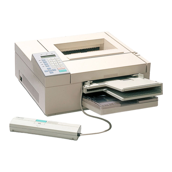
Page: 4 Service Guide DOC-IT3000/4000 Chapter 1 Product Specifications 1.1 GENERAL SPECIFICATIONS 1.1.01 Physical Dimensions · Width - 17.75 inches (Approximately 450mm) · Depth - 16.9 inches (Approximately 430mm ) · Height - 7.1 inches (Approximately 180mm) · Weight - 36 lbs. (Approximately 15kg) 1.1.02 Ambient Temperature and Relative Humidity (RH) - Page 13 Note: Documents must be placed face up on the Automatic Document Feeder (ADF) Tray. Copyright 1997, Okidata, Division of OKI America, Inc. All rights reserved. See the OKIDATA Business Partner Exchange (BPX) for any updates to this material. (http://bpx.okidata.com)
-
Page 14: Doc-It Controller Specifications
1.2.05 DOC-IT Interface · Video Interface Printer Scanner Copier · Asynchronous Serial Interface (9600 bps) Facsimile Copyright 1997, Okidata, Division of OKI America, Inc. All rights reserved. See the OKIDATA Business Partner Exchange (BPX) for any updates to this material. (http://bpx.okidata.com) -
Page 15: Printer Specifications
Page: 6 Service Guide DOC-IT3000/4000 Chapter 1 Product Specifications 1.3 PRINTER SPECIFICATIONS 1.3.01 Print Method · Exposure Method - Stationary LED Head · Development Agent - Dry Toner · Fusing Method - Heat/Pressure Rollers 1.3.02 Printer Emulations Emulation DOC-IT 3000 DOC-IT 4000 PCL 4.5 (HP IIP) - Page 16 · Second Cassette (Requires the installation of an optional Second Paper Feed Unit) - 200 sheets Copyright 1997, Okidata, Division of OKI America, Inc. All rights reserved. See the OKIDATA Business Partner Exchange (BPX) for any updates to this material. (http://bpx.okidata.com)
-
Page 17: Facsimile Specifications
Page: 7 Service Guide DOC-IT3000/4000 Chapter 1 Product Specifications 1.4 FACSIMILE SPECIFICATIONS 1.4.01 Compatibility · CCITT Group 3 ONLY 1.4.02 Telephone Line Requirement · PSTN (Public Switched Telephone Network) 1.4.03 Communication Mode · Half Duplex 1.4.04 Protocol · CCITT Rec.T.30 1.4.05 Coding Schemes... - Page 18 · Gray Scale with Bayer Dither · Gray Scale with Vertical Line Dither 1.4.12 Ringer Equivalence Number · 0.68 Copyright 1997, Okidata, Division of OKI America, Inc. All rights reserved. See the OKIDATA Business Partner Exchange (BPX) for any updates to this material. (http://bpx.okidata.com)
-
Page 19: Scanner Specifications
Page: 8 Service Guide DOC-IT3000/4000 Chapter 1 Product Specifications 1.5 SCANNER SPECIFICATIONS 1.5.01 Scanning Device · 4,096 bit Charge Coupled Device (CCD) 1.5.02 Scanning Method · Automatic Document Feeder (ADF) · Handheld 1.5.03 Scanning Speed · ADF: 4.4 seconds for a letter size sheet 1.5.04 Effective Reading Width... - Page 20 - IMG: Digital Research (GEM) Image File - BMP: WINDOWS Image File - TIF: 16 Level Gray Scale Copyright 1997, Okidata, Division of OKI America, Inc. All rights reserved. See the OKIDATA Business Partner Exchange (BPX) for any updates to this material. (http://bpx.okidata.com)
-
Page 21: Copier Specifications
· DOC-IT 3000 - 300 dots per inch · DOC-IT 4000 - 400 dots per inch Copyright 1997, Okidata, Division of OKI America, Inc. All rights reserved. See the OKIDATA Business Partner Exchange (BPX) for any updates to this material. (http://bpx.okidata.com) -
Page 22: Options
It must be purchased separately. 1.7.04 Printer Emulations · Refer to Section 1.3.02 for available emulations Copyright 1997, Okidata, Division of OKI America, Inc. All rights reserved. See the OKIDATA Business Partner Exchange (BPX) for any updates to this material. (http://bpx.okidata.com) -
Page 23: Consumables
- LED Lens Cleaner Pad · Image Drum Cartridge Kit - Image Drum - Ozone Filter Copyright 1997, Okidata, Division of OKI America, Inc. All rights reserved. See the OKIDATA Business Partner Exchange (BPX) for any updates to this material. (http://bpx.okidata.com) -
Page 24: Reliability Data
1.9.07 Mean Time Between Failure (MTBF) · Approximately 17,250 hours 1.9.08 Mean Time To Repair (MTTR) · Approximately 30 minutes Copyright 1997, Okidata, Division of OKI America, Inc. All rights reserved. See the OKIDATA Business Partner Exchange (BPX) for any updates to this material. (http://bpx.okidata.com) -
Page 25: Agency Approvals
· Electro-Magnetic Interference (EMI) - FCC Part 15, Class B · Communication - FCC Part 68 Copyright 1997, Okidata, Division of OKI America, Inc. All rights reserved. See the OKIDATA Business Partner Exchange (BPX) for any updates to this material. (http://bpx.okidata.com) -
Page 26: Principles Of Operation
Page: 14 Service Guide DOC-IT3000/4000 Chapter 2 Principles of Operation 2.1 ELECTRICAL PRINCIPLES OF OPERATION {doclinks} Copyright 1997, Okidata, Division of OKI America, Inc. All rights reserved. See the OKIDATA Business Partner Exchange (BPX) for any updates to this material. (http://bpx.okidata.com) -
Page 27: Main Control Board
Page: 15 Service Guide DOC-IT3000/4000 Chapter 2 Principles of Operation 2.1.01 Main Control Board The main control board controls reception of the data through a host I/F, processes command analysis, controls the scanner unit, outputs data, and controls the operation panel. - Page 28 Copyright 1997, Okidata, Division of OKI America, Inc. All rights reserved. See the OKIDATA Business Partner Exchange (BPX) for any updates to this material. (http://bpx.okidata.com)
- Page 29 Controller has been programmed so that proper processing is selected when a signal is input according to an internal table of the CPU. Copyright 1997, Okidata, Division of OKI America, Inc. All rights reserved. See the OKIDATA Business Partner Exchange (BPX) for any updates to this material. (http://bpx.okidata.com)
- Page 30 Memory Map (on Master CPU Side) The memory layout of the Doc-It Engine is shown below. Copyright 1997, Okidata, Division of OKI America, Inc. All rights reserved. See the OKIDATA Business Partner Exchange (BPX) for any updates to this material. (http://bpx.okidata.com)
-
Page 31: Address Decoder
MA7 and high-order addresses MA8 through MA15 output from the CPU 80C154 using 74S138. Copyright 1997, Okidata, Division of OKI America, Inc. All rights reserved. See the OKIDATA Business Partner Exchange (BPX) for any updates to this material. (http://bpx.okidata.com) -
Page 32: Program Rom
Chapter 2 Principles of Operation Program ROM The standard capacity of the program ROM is 64K bytes. Copyright 1997, Okidata, Division of OKI America, Inc. All rights reserved. See the OKIDATA Business Partner Exchange (BPX) for any updates to this material. (http://bpx.okidata.com) -
Page 33: Ram
- The memory capacity of the RAM 6264 is 8K bytes. The RAM 6264 is selected by decoding high-order addresses A13 through A15 output from the CPU 80C154 using an address decoder. The RAM address space is 0000 to 1FFF. Copyright 1997, Okidata, Division of OKI America, Inc. All rights reserved. See the OKIDATA Business... - Page 34 Partner Exchange (BPX) for any updates to this material. (http://bpx.okidata.com)
-
Page 35: Write 1 Waveforms (Oe Clock)
Page: 21 Service Guide DOC-IT3000/4000 Chapter 2 Principles of Operation WRITE 1 Waveforms (OE Clock) Copyright 1997, Okidata, Division of OKI America, Inc. All rights reserved. See the OKIDATA Business Partner Exchange (BPX) for any updates to this material. (http://bpx.okidata.com) -
Page 36: Image Control Lsi
- Processing speed is more than approximately 200ns per pixel. - +5vdc single power supply Copyright 1997, Okidata, Division of OKI America, Inc. All rights reserved. See the OKIDATA Business Partner Exchange (BPX) for any updates to this material. (http://bpx.okidata.com) -
Page 37: Memory Configuration
· Line buffer for brightness compensation (8-bit, 2-line) · Clear (RESET) timing chart Copyright 1997, Okidata, Division of OKI America, Inc. All rights reserved. See the OKIDATA Business Partner Exchange (BPX) for any updates to this material. (http://bpx.okidata.com) -
Page 38: External Ram Access
Page: 24 Service Guide DOC-IT3000/4000 Chapter 2 Principles of Operation External RAM Access Copyright 1997, Okidata, Division of OKI America, Inc. All rights reserved. See the OKIDATA Business Partner Exchange (BPX) for any updates to this material. (http://bpx.okidata.com) -
Page 39: Scanner Control Lsi
- Generates two interrupt signals (INT0 and INT1) to CPU. · Input/output circuit · Watchdog timer · CPU interface block Copyright 1997, Okidata, Division of OKI America, Inc. All rights reserved. See the OKIDATA Business Partner Exchange (BPX) for any updates to this material. (http://bpx.okidata.com) -
Page 40: Line Memory Read/Write Waveforms
Page: 26 Service Guide DOC-IT3000/4000 Chapter 2 Principles of Operation Line Memory Read/Write Waveforms... - Page 42 Copyright 1997, Okidata, Division of OKI America, Inc. All rights reserved. See the OKIDATA Business Partner Exchange (BPX) for any updates to this material. (http://bpx.okidata.com)
-
Page 43: Peripheral Interface Controller
The information of sensor conditions on ADF, signals of print control CPU, and signals for A/D converter circuit are input and output. Copyright 1997, Okidata, Division of OKI America, Inc. All rights reserved. See the OKIDATA Business Partner Exchange (BPX) for any updates to this material. (http://bpx.okidata.com) -
Page 44: Operator Panel
- LCD display (16 characters x 2 lines) - LEDs - Operation key switches - Buzzer Copyright 1997, Okidata, Division of OKI America, Inc. All rights reserved. See the OKIDATA Business Partner Exchange (BPX) for any updates to this material. (http://bpx.okidata.com) -
Page 45: Serial Video Interface
Service Guide DOC-IT3000/4000 Chapter 2 Principles of Operation Serial Video Interface · Electrical Condition of DPS Interface Copyright 1997, Okidata, Division of OKI America, Inc. All rights reserved. See the OKIDATA Business Partner Exchange (BPX) for any updates to this material. (http://bpx.okidata.com) -
Page 46: Image Sensor Control Board
· LED ON/OFF control · Start switch detection · Supply of CLK SH signal to image sensor Copyright 1997, Okidata, Division of OKI America, Inc. All rights reserved. See the OKIDATA Business Partner Exchange (BPX) for any updates to this material. (http://bpx.okidata.com) - Page 47 · Main Control Board - Video interfaces (MSM75V039-PPB interface) - Second tray interface (MSM75V039) (OPTION) Copyright 1997, Okidata, Division of OKI America, Inc. All rights reserved. See the OKIDATA Business Partner Exchange (BPX) for any updates to this material. (http://bpx.okidata.com)
-
Page 48: Printer Unit Block Diagram
Page: 32 Service Guide DOC-IT3000/4000 Chapter 2 Principles of Operation Printer Unit Block Diagram Copyright 1997, Okidata, Division of OKI America, Inc. All rights reserved. See the OKIDATA Business Partner Exchange (BPX) for any updates to this material. (http://bpx.okidata.com) -
Page 49: Printer Control Board
Page: 33 Service Guide DOC-IT3000/4000 Chapter 2 Principles of Operation 2.2.02 Printer Control Board The Printer Control Board is composed of an MPU80C154, MSM75V039, ROM and EEPROM. · MPU80C154 - 8-bit CPU - Internal RAM: 128 bytes - I/O ports: 32... - Page 50 - LSYNC period set circuit - The LSYNC period set circuit sets the time of one LSYNC period corresponding to one line. - The time of the LSYNC period is usually set when the power of the Doc-It Engine is turned on and when the vertical resolution setting and print speed setting are altered.
- Page 51 Copyright 1997, Okidata, Division of OKI America, Inc. All rights reserved. See the OKIDATA Business Partner Exchange (BPX) for any updates to this material. (http://bpx.okidata.com)
-
Page 52: Fuser Unit
Page: 34 Service Guide DOC-IT3000/4000 Chapter 2 Principles of Operation 2.2.03 Fuser Unit The fuser unit heater is controlled by a thermistor, a comparator, an LSI, and a CPU to keep the heat roller surface temperature within a predetermined range (about 180 degrees centigrade). - Page 53 3,4 ) The CPU, on detection of a fuser alarm, comes to a halt after printing the current page. Copyright 1997, Okidata, Division of OKI America, Inc. All rights reserved. See the OKIDATA Business Partner Exchange (BPX) for any updates to this material. (http://bpx.okidata.com)
-
Page 54: Main Motor
Page: 35 Service Guide DOC-IT3000/4000 Chapter 2 Principles of Operation 2.2.04 Main Motor This pulse motor is driven by the motor drive IC(M54646). It is two-phase excited and bipolar-driven according to the DM-PH0 and DM-PH1 signals generated from the LSI. The level of the input voltage to the VR1 and VR2 terminals is compared with that of the voltage drop across R35, R36, R94 and R95 fed back to pins 1 and 28. - Page 55 Copyright 1997, Okidata, Division of OKI America, Inc. All rights reserved. See the OKIDATA Business Partner Exchange (BPX) for any updates to this material. (http://bpx.okidata.com)
-
Page 56: Led Array
Page: 36 Service Guide DOC-IT3000/4000 Chapter 2 Principles of Operation 2.2.05 LED Array Data on the 2,560 LEDs (300 dpi), 3,456 (400 dpi) in the LED head is set in the shift register by the HD CLK signal. After the 2,560-bit data is thus set in the shift register, it is subsequently loaded in the latch circuit by the HD LD signal. - Page 57 Copyright 1997, Okidata, Division of OKI America, Inc. All rights reserved. See the OKIDATA Business Partner Exchange (BPX) for any updates to this material. (http://bpx.okidata.com)
-
Page 58: Sensor And Switch Control
· Inlet sensor · Outlet sensor · Paper tray identification switch · Paper end sensor Copyright 1997, Okidata, Division of OKI America, Inc. All rights reserved. See the OKIDATA Business Partner Exchange (BPX) for any updates to this material. (http://bpx.okidata.com) -
Page 59: Resist Motor
This pulse motor is driven clockwise or counterclockwise. It is four-phase excited and unipolar-driven according to the RM-01, RM-02, and RM ON-P signals generated from the LSI. Copyright 1997, Okidata, Division of OKI America, Inc. All rights reserved. See the OKIDATA Business Partner Exchange (BPX) for any updates to this material. (http://bpx.okidata.com) -
Page 60: Fan
6. The fan is driven 1 minute after the heater has stopped. The fan speed is reduced if the next PRINT signal is not received during 1 minute. Copyright 1997, Okidata, Division of OKI America, Inc. All rights reserved. See the OKIDATA Business Partner Exchange (BPX) for any updates to this material. (http://bpx.okidata.com) -
Page 61: Main Control Board
This LSI (MSM75V039) has a one-byte send buffer and one-byte receive buffer as the interface with a main CPU and supervises MREQ-P and SREQ-P signals mutually for communication. Copyright 1997, Okidata, Division of OKI America, Inc. All rights reserved. See the OKIDATA Business Partner Exchange (BPX) for any updates to this material. (http://bpx.okidata.com) -
Page 62: Video Interface
LSYNC, generated from the print LSI, is a line synchronizing signal. It is generated for each dot line. Copyright 1997, Okidata, Division of OKI America, Inc. All rights reserved. See the OKIDATA Business Partner Exchange (BPX) for any updates to this material. (http://bpx.okidata.com) -
Page 63: Second Tray Interface
The second tray interface consists of an 8-bit shift register, 2-bit mode register, 8-clock counter, and its related circuit. This interface is used to input or output serial data. Copyright 1997, Okidata, Division of OKI America, Inc. All rights reserved. See the OKIDATA Business Partner Exchange (BPX) for any updates to this material. (http://bpx.okidata.com) -
Page 64: Block Diagram Of Serial Interface
The output signal at the OPSC pin is then kept high. Copyright 1997, Okidata, Division of OKI America, Inc. All rights reserved. See the OKIDATA Business Partner Exchange (BPX) for any updates to this material. (http://bpx.okidata.com) -
Page 65: Power Supply Unit
+38 vdc Motor and fan drive voltage, and high-voltage source voltage · High voltages +5 Kvdc Charge voltage (transfer) -6 Kvdc Charge voltage (charging) Copyright 1997, Okidata, Division of OKI America, Inc. All rights reserved. See the OKIDATA Business Partner Exchange (BPX) for any updates to this material. (http://bpx.okidata.com) -
Page 66: High-Voltage Generation
(LLBB-PCB). It is kept at about -700 vdc during charging. Copyright 1997, Okidata, Division of OKI America, Inc. All rights reserved. See the OKIDATA Business Partner Exchange (BPX) for any updates to this material. (http://bpx.okidata.com) -
Page 67: Reset Control
It turns on +5 vdc after generating a reset signal. Copyright 1997, Okidata, Division of OKI America, Inc. All rights reserved. See the OKIDATA Business Partner Exchange (BPX) for any updates to this material. (http://bpx.okidata.com) -
Page 68: Power Supply Control Signals
Page: 47 Service Guide DOC-IT3000/4000 Chapter 2 Principles of Operation Power Supply Control Signals Copyright 1997, Okidata, Division of OKI America, Inc. All rights reserved. See the OKIDATA Business Partner Exchange (BPX) for any updates to this material. (http://bpx.okidata.com) -
Page 69: Doc-It Controller
This flexibility allows easy updates to software (firmware), printer emulation code, and fonts. Copyright 1997, Okidata, Division of OKI America, Inc. All rights reserved. See the OKIDATA Business Partner Exchange (BPX) for any updates to this material. (http://bpx.okidata.com) -
Page 70: Doc-It Controller Block Diagram
Page: 49 Service Guide DOC-IT3000/4000 Chapter 2 Principles of Operation 2.3.01 Doc-It Controller Block Diagram The Doc-It Controller has five major functional blocks. They are as follows. · 80960KB Processor - The 80960KB operating at 16MHz or 20MHz is a 32 bit processor designed for imbedded applications. - Page 71 (PSTN) through the Data Access Arrangement (DAA). The DAA controls hook switch, sends out dial pulses and detects rings. Copyright 1997, Okidata, Division of OKI America, Inc. All rights reserved. See the OKIDATA Business Partner Exchange (BPX) for any updates to this material. (http://bpx.okidata.com)
-
Page 72: Doc-It Host Communication Controller
Page: 50 Service Guide DOC-IT3000/4000 Chapter 2 Principles of Operation 2.3.02 Doc-It Host Communication Controller The Host Communications Controller (HCC) is an Oki proprietary ASIC which handles the communications between the PC host and the i80960 processor. The key features are listed below. - Page 73 mode the address of the local bus memory is the result of offset address (programmed in the Doc-It Controller Extended Memory Configuration Register plus the Extended Memory Starting Address bits of the Extended Memory Configuration Register 1. This mode of operation is supported via the Developers Toolkit software.
- Page 74 Copyright 1997, Okidata, Division of OKI America, Inc. All rights reserved. See the OKIDATA Business Partner Exchange (BPX) for any updates to this material. (http://bpx.okidata.com)
-
Page 75: Doc-It Integrated Peripheral Controller
Page: 51 Service Guide DOC-IT3000/4000 Chapter 2 Principles of Operation 2.3.03 Doc-It Integrated Peripheral Controller The IPC (Integrated Peripheral Controller) is the Oki proprietary ASIC which serves as the control center of the Doc-It Controller. It is a highly integrated scan, print, FAX and copy control unit. The IPC is programmed by either the i960 CPU or the PC-AT (via the HCC ASIC). - Page 76 - (address range 8000 0000 to 87FF FFFF) · Slow I/O bus cycle - (address range 1000 0000 to 7FFF FFFF and 8800 0000 to EFFF FFFF) The bus handshake control logic controls all the bus traffic and provides the request signals for the memory interface, DMA controller, Doc-It Engine interface and DAA interface.
- Page 77 request has the highest priority of all requests for memory. The duration of refresh is programmable. In order to achieve zero wait state timing under a variety of system speeds, there are two sets of CAS timing control logic (16 and 25MHz). One wait state is required for DRAM writes at 25MHz. All reads at any system speed and writes below 25MHz can operate at 0 wait states, assuming the 64 bit (odd/even, MDO[31:0] and MDE[31:0]) double banking path is chosen.
- Page 78 · Control of the optional monitor speaker , to monitor the modem tones and voice chip tones which are transmitted or received on the subscriber line. Copyright 1997, Okidata, Division of OKI America, Inc. All rights reserved. See the OKIDATA Business Partner Exchange (BPX) for any updates to this material. (http://bpx.okidata.com)
-
Page 79: Mechanical Operation
The electrophotographic technology used in this printer is similar to that embodied in general copying machines. The technology comprises the following processes. Copyright 1997, Okidata, Division of OKI America, Inc. All rights reserved. See the OKIDATA Business Partner Exchange (BPX) for any updates to this material. (http://bpx.okidata.com) -
Page 80: Electrostatic Printing - Overview
Fusing - The toner image transferred to the paper is fused under heat and pressure. Copyright 1997, Okidata, Division of OKI America, Inc. All rights reserved. See the OKIDATA Business Partner Exchange (BPX) for any updates to this material. (http://bpx.okidata.com) - Page 81 The following page shows the layout of the printing process hardware. Copyright 1997, Okidata, Division of OKI America, Inc. All rights reserved. See the OKIDATA Business Partner Exchange (BPX) for any updates to this material. (http://bpx.okidata.com)
- Page 82 Turning the resist motor in the (b) direction drives the feed roller in the (B) direction. Copyright 1997, Okidata, Division of OKI America, Inc. All rights reserved. See the OKIDATA Business Partner Exchange (BPX) for any updates to this material. (http://bpx.okidata.com)
- Page 83 (The skew in the paper can thus be corrected). Copyright 1997, Okidata, Division of OKI America, Inc. All rights reserved. See the OKIDATA Business Partner Exchange (BPX) for any updates to this material. (http://bpx.okidata.com)
- Page 84 Chapter 2 Principles of Operation Feeding After the end of hopping, the feed roller turns to advance the paper. Copyright 1997, Okidata, Division of OKI America, Inc. All rights reserved. See the OKIDATA Business Partner Exchange (BPX) for any updates to this material. (http://bpx.okidata.com)
- Page 85 To prevent this, a fan motor removes ozone around the charge wire. Copyright 1997, Okidata, Division of OKI America, Inc. All rights reserved. See the OKIDATA Business Partner Exchange (BPX) for any updates to this material. (http://bpx.okidata.com)
- Page 86 Page: 59 Service Guide DOC-IT3000/4000 Chapter 2 Principles of Operation Exposure Light emitted from the LED head is radiated to the image drum surface charged with negative charges. The surface potential falls on the irradiated part of the image drum surface, thereby forming a latent image associated with the image signal.
- Page 87 The radiated part of the image drum surface is kept at about -100vdc. Copyright 1997, Okidata, Division of OKI America, Inc. All rights reserved. See the OKIDATA Business Partner Exchange (BPX) for any updates to this material. (http://bpx.okidata.com)
- Page 88 Page: 60 Service Guide DOC-IT3000/4000 Chapter 2 Principles of Operation Developing Toner is attracted to the latent image on the image drum surface to convert it into a visible toner image. Developing takes place at the contact between the image drum and the developing roller.
- Page 89 (as shown below). -500vdc is supplied to the toner supply roller, -400vdc to the developing roller. Copyright 1997, Okidata, Division of OKI America, Inc. All rights reserved. See the OKIDATA Business Partner Exchange (BPX) for any updates to this material. (http://bpx.okidata.com)
- Page 90 Toner charged negative that is attracted to the image drum surface is transferred to the paper by the positive charge on it. Copyright 1997, Okidata, Division of OKI America, Inc. All rights reserved. See the OKIDATA Business Partner Exchange (BPX) for any updates to this material. (http://bpx.okidata.com)
- Page 91 The toner thus scraped off is returned from the toner recovery unit to the developer station by the toner recycling unit for reuse. Copyright 1997, Okidata, Division of OKI America, Inc. All rights reserved. See the OKIDATA Business Partner Exchange (BPX) for any updates to this material. (http://bpx.okidata.com)
- Page 92 The heater roller is held under a pressure of 3kg from the pressure spring on each side. Copyright 1997, Okidata, Division of OKI America, Inc. All rights reserved. See the OKIDATA Business Partner Exchange (BPX) for any updates to this material. (http://bpx.okidata.com)
-
Page 93: Paper Ejection
Once paper leaves the fuser unit, it is ejected from the Doc-it by the paper eject roller. The paper can be ejected with the printed side up or down. Copyright 1997, Okidata, Division of OKI America, Inc. All rights reserved. See the OKIDATA Business Partner Exchange (BPX) for any updates to this material. (http://bpx.okidata.com) -
Page 94: Toner Recycling
Toner recovered by the cleaning blade is collected in the toner recovery tank before it is moved to the toner cartridge by the toner recycling unit for reuse. Copyright 1997, Okidata, Division of OKI America, Inc. All rights reserved. See the OKIDATA Business Partner Exchange (BPX) for any updates to this material. (http://bpx.okidata.com) -
Page 95: Adf Hopping And Feeding
Page: 66 Service Guide DOC-IT3000/4000 Chapter 2 Principles of Operation 2.4.04 ADF Hopping and Feeding Hopping and feeding are accomplished by a single motor as shown below. · Hopping Hopping turns the hopping roller to advance the paper until the inlet sensor turns on. - Page 96 Copyright 1997, Okidata, Division of OKI America, Inc. All rights reserved. See the OKIDATA Business Partner Exchange (BPX) for any updates to this material. (http://bpx.okidata.com)
-
Page 97: Sensors And Switches
Page: 67 Service Guide DOC-IT3000/4000 Chapter 2 Principles of Operation 2.4.05 Sensors and Switches Inlet Sensor (Photosensor) Outlet Sensor (Photosensor) Paper Tray Identification Switch... - Page 98 Paper End Sensor (Photosensor) Cover Open Switch...
- Page 99 Copyright 1997, Okidata, Division of OKI America, Inc. All rights reserved. See the OKIDATA Business Partner Exchange (BPX) for any updates to this material. (http://bpx.okidata.com)
-
Page 100: Alarm Detection
If the leading part of the paper does not reach the outlet sensor within a predetermined period of time after the timing sensor is on, a feed jam error is established. Copyright 1997, Okidata, Division of OKI America, Inc. All rights reserved. See the OKIDATA Business Partner Exchange (BPX) for any updates to this material. (http://bpx.okidata.com) -
Page 101: Software Configuration
- DOS 3.3 or above - At least 10 Mbytes of disk space - Mouse Copyright 1997, Okidata, Division of OKI America, Inc. All rights reserved. See the OKIDATA Business Partner Exchange (BPX) for any updates to this material. (http://bpx.okidata.com) -
Page 102: File Descriptions
Page: 70 Service Guide DOC-IT3000/4000 Chapter 2 Principles of Operation 2.5.03 File Descriptions The following table describes the main files that are included with the Doc-It Manager software. File Description BDDP.COM Memory resident program (TSR) which installs itself at system boot time and handles communications between the PC and the Doc-It Controller board. - Page 103 Holds outgoing FAX - Those that have been sent or will be sent. DOCIT/IMAGE Holds image files - supports file formats. TIFF FAX and OKI Copyright 1997, Okidata, Division of OKI America, Inc. All rights reserved. See the OKIDATA Business Partner Exchange (BPX) for any updates to this material. (http://bpx.okidata.com)
-
Page 104: Software Power-Up Sequence
See Section 4 ( ) for more information regarding possible error messages from the POWERON.EXE program . Copyright 1997, Okidata, Division of OKI America, Inc. All rights reserved. See the OKIDATA Business Partner Exchange (BPX) for any updates to this material. (http://bpx.okidata.com) -
Page 105: Software Functional Components
Page: 72 Service Guide DOC-IT3000/4000 Chapter 2 Principles of Operation 2.5.05 Software Functional Components Multi-Tasking Kernel The heart of the DOC-IT 3000/4000 system is the Multi-Tasking Kernel (MTK). This kernel permits multiple system functions to run concurrently, providing both a hardware and software interface as well as services to the Doc-It control modules. - Page 106 Task App to Copy Scan to RX FAX RX Fax Execute Print Doc-It to HD to Print from from file from d Later or buffer scanner App to ----- Print Copy ----- Scan to ----- Doc-It RX FAX ----- to HD RX FAX ----- to Print...
- Page 107 Copyright 1997, Okidata, Division of OKI America, Inc. All rights reserved. See the OKIDATA Business Partner Exchange (BPX) for any updates to this material. (http://bpx.okidata.com)
- Page 108 Page: 73 Service Guide DOC-IT3000/4000 Chapter 2 Principles of Operation Kernel Primitives The kernel primitives fall into the following categories: · Kernel Initialization which establishes the kernel operating environment. · Task Management with primitives to create, manage, and schedule tasks in a multi-tasking environment.
- Page 109 module on the Controller. The communications between the PC and the Controller is achieved by using a Page Frame technique which is used by Expanded Memory Manager (EMM) implementations. By using this technique, any segment of the controllers memory can be mapped and accessed directly from the PC host side.
- Page 110 Controller memory. Copyright 1997, Okidata, Division of OKI America, Inc. All rights reserved. See the OKIDATA Business Partner Exchange (BPX) for any updates to this material. (http://bpx.okidata.com)
-
Page 111: Maintenance & Disassembly
The Doc-It 3000/4000 is a xerographic device. Cleaning procedures must be performed correctly if high print quality is to be achieved. Copyright 1997, Okidata, Division of OKI America, Inc. All rights reserved. See the OKIDATA Business Partner Exchange (BPX) for any updates to this material. (http://bpx.okidata.com) -
Page 112: Maintenance Precautions
Page: 75 Service Guide DOC-IT3000/4000 Chapter 3 Maintenance & Disassembly 3.1.02 Maintenance Precautions · Do not disassemble the Doc-It 3000/4000 if it is operating normally. · Before starting disassembly and reassembly, always turn the AC power switch OFF and pull out the AC plug. - Page 113 Copyright 1997, Okidata, Division of OKI America, Inc. All rights reserved. See the OKIDATA Business Partner Exchange (BPX) for any updates to this material. (http://bpx.okidata.com)
-
Page 114: Maintenance Tools
· Needle Nose Pliers (4 Inch) · Feeler Gauge (capable of measuring .04 to .05 inches) · Digital Multimeter Copyright 1997, Okidata, Division of OKI America, Inc. All rights reserved. See the OKIDATA Business Partner Exchange (BPX) for any updates to this material. (http://bpx.okidata.com) -
Page 115: Disassembly/Assembly Procedures
This section contains the disassembly procedures. Only the removal procedures are explained here. Reverse the procedure for the installation. At the bottom of each procedure is a listing of Okidata part numbers, item descriptions, and cross-references to Appendix B. Items included in the Recommended Spare Parts List are designated RSPL. - Page 116 7. To replace the engine controller board, you would perform the following procedures: 3.2.01, 3.2.05, 3.2.06, 3.2.23, and 3.2.29. Copyright 1997, Okidata, Division of OKI America, Inc. All rights reserved. See the OKIDATA Business Partner Exchange (BPX) for any updates to this material. (http://bpx.okidata.com)
- Page 117 Page: 78 Service Guide DOC-IT3000/4000 Chapter 3 Maintenance & Disassembly Flowchart Index Procedure Flowchart Procedure Flowchart Number Page Number Page 3.2.01 3.2.38 3.2.02 3.2.39 3.2.03 3.2.40 3.2.04 3.2.41 3.2.05 3.2.42 3.2.06 3.2.43 3.2.07 3.2.44 3.2.08 3.2.45 3.2.09 3.2.46 3.2.10 3.2.47 3.2.11...
- Page 118 3.2.26 3.2.63 3.2.27 3.2.64 3.2.28 3.2.65 3.2.29 3.2.30 3.2.31 3.2.32 3.2.33 3.2.34 3.2.35 3.2.36 3.2.37 Copyright 1997, Okidata, Division of OKI America, Inc. All rights reserved. See the OKIDATA Business Partner Exchange (BPX) for any updates to this material. (http://bpx.okidata.com)
- Page 119 Page: 79 Service Guide DOC-IT3000/4000 Chapter 3 Maintenance & Disassembly...
- Page 120 Copyright 1997, Okidata, Division of OKI America, Inc. All rights reserved. See the OKIDATA Business Partner Exchange (BPX) for any updates to this material. (http://bpx.okidata.com)
- Page 121 Page: 80 Service Guide DOC-IT3000/4000 Chapter 3 Maintenance & Disassembly...
- Page 122 Copyright 1997, Okidata, Division of OKI America, Inc. All rights reserved. See the OKIDATA Business Partner Exchange (BPX) for any updates to this material. (http://bpx.okidata.com)
- Page 123 Page: 81 Service Guide DOC-IT3000/4000 Chapter 3 Maintenance & Disassembly...
- Page 124 Copyright 1997, Okidata, Division of OKI America, Inc. All rights reserved. See the OKIDATA Business Partner Exchange (BPX) for any updates to this material. (http://bpx.okidata.com)
- Page 125 Page: 82 Service Guide DOC-IT3000/4000 Chapter 3 Maintenance & Disassembly...
- Page 126 Copyright 1997, Okidata, Division of OKI America, Inc. All rights reserved. See the OKIDATA Business Partner Exchange (BPX) for any updates to this material. (http://bpx.okidata.com)
- Page 127 Page: 83 Service Guide DOC-IT3000/4000 Chapter 3 Maintenance & Disassembly...
- Page 128 Copyright 1997, Okidata, Division of OKI America, Inc. All rights reserved. See the OKIDATA Business Partner Exchange (BPX) for any updates to this material. (http://bpx.okidata.com)
- Page 129 Page: 84 Service Guide DOC-IT3000/4000 Chapter 3 Maintenance & Disassembly...
- Page 130 Copyright 1997, Okidata, Division of OKI America, Inc. All rights reserved. See the OKIDATA Business Partner Exchange (BPX) for any updates to this material. (http://bpx.okidata.com)
- Page 131 Page: 85 Service Guide DOC-IT3000/4000 Chapter 3 Maintenance & Disassembly Page 8 Page 9 Copyright 1997, Okidata, Division of OKI America, Inc. All rights reserved. See the OKIDATA Business Partner Exchange (BPX) for any updates to this material. (http://bpx.okidata.com)
-
Page 132: Preliminary Items
Page: 86 Service Guide DOC-IT3000/4000 Chapter 3 Maintenance & Disassembly 3.2.01 Preliminary Items · Turn the power switch (1) OFF. · Detach the AC power cord (2). · Detach the interface cable (3). · Detach the phone cord. (Not shown) ·... - Page 133 Copyright 1997, Okidata, Division of OKI America, Inc. All rights reserved. See the OKIDATA Business Partner Exchange (BPX) for any updates to this material. (http://bpx.okidata.com)
-
Page 134: Ozone Filter
Page: 87 Service Guide DOC-IT3000/4000 Chapter 3 Maintenance & Disassembly 3.2.02 Ozone Filter Note: A replacement ozone filter is provided with the image drum cartridge kit. The filter should be replaced when the image drum cartridge is replaced. · Using a screwdriver, insert the blade under the lower portion of the fan cover (1) and twist the screwdriver to remove the fan cover. - Page 135 Copyright 1997, Okidata, Division of OKI America, Inc. All rights reserved. See the OKIDATA Business Partner Exchange (BPX) for any updates to this material. (http://bpx.okidata.com)
-
Page 136: Transfer Charger Assembly
Page: 88 Service Guide DOC-IT3000/4000 Chapter 3 Maintenance & Disassembly 3.2.03 Transfer Charger Assembly Note: Make sure the image drum cartridge is removed before performing this procedure. The image drum cartridge must be protected from light when it is not installed. - Page 137 Copyright 1997, Okidata, Division of OKI America, Inc. All rights reserved. See the OKIDATA Business Partner Exchange (BPX) for any updates to this material. (http://bpx.okidata.com)
-
Page 138: Led Head
Page: 89 Service Guide DOC-IT3000/4000 Chapter 3 Maintenance & Disassembly 3.2.04 LED Head · Open the stacker cover. · Push the two blue lock levers (1) toward the rear of the printer and open the LED holder (2). · Squeeze the LED head (3) and the LED holder together. This eases the tension on the springs (4). - Page 139 Copyright 1997, Okidata, Division of OKI America, Inc. All rights reserved. See the OKIDATA Business Partner Exchange (BPX) for any updates to this material. (http://bpx.okidata.com)
-
Page 140: Operator Panel Assembly
Page: 90 Service Guide DOC-IT3000/4000 Chapter 3 Maintenance & Disassembly 3.2.05 Operator Panel Assembly · Press at A and lift the operator panel assembly (1). · Turn the assembly over. · Detach the cable (2) from connector CN1. · Remove the assembly. - Page 141 Copyright 1997, Okidata, Division of OKI America, Inc. All rights reserved. See the OKIDATA Business Partner Exchange (BPX) for any updates to this material. (http://bpx.okidata.com)
-
Page 142: Upper Cover
Page: 91 Service Guide DOC-IT3000/4000 Chapter 3 Maintenance & Disassembly 3.2.06 Upper Cover · Press at B and open the scanner cover (1). · Press the scanner eject lever (2) back and lift out the handheld scanner unit (3), working the scanner cable (4) free of the guides ·... - Page 143 Copyright 1997, Okidata, Division of OKI America, Inc. All rights reserved. See the OKIDATA Business Partner Exchange (BPX) for any updates to this material. (http://bpx.okidata.com)
-
Page 144: Stacker Open And Scanner Open Lever Assemblies
· Remove the screw, metal plate, and bracket with spring. · Remove the screw, bracket, and scanner cover lever. Note: The metal springs and rollers are located at the rear of the cover. Copyright 1997, Okidata, Division of OKI America, Inc. All rights reserved. See the OKIDATA Business... - Page 145 Partner Exchange (BPX) for any updates to this material. (http://bpx.okidata.com)
-
Page 146: Automatic Document Feed (Adf) Unit
CAUTION: The ADF Unit Assembly is an RSPL item. Okidata DOES NOT recommend disassembling this unit. The parts, boards and sensors contained in the ADF Unit Assembly are not available as spare parts. Refer to Section 3.3 of this Service Handbook for adjustment and counter information B.2.11... - Page 147 Copyright 1997, Okidata, Division of OKI America, Inc. All rights reserved. See the OKIDATA Business Partner Exchange (BPX) for any updates to this material. (http://bpx.okidata.com)
-
Page 148: Mini-Pitch Belt (Adf)
Page: 94 Service Guide DOC-IT3000/4000 Chapter 3 Maintenance & Disassembly 3.2.09 Mini-Pitch Belt (ADF) · Remove the preliminary items. · Remove the upper cover. · Remove the ADF unit. · Remove mini-pitch belt (1). P/N 51304601 Mini-Pitch Belt (ADF) RSPL... - Page 149 Copyright 1997, Okidata, Division of OKI America, Inc. All rights reserved. See the OKIDATA Business Partner Exchange (BPX) for any updates to this material. (http://bpx.okidata.com)
-
Page 150: Adf Gears
Page: 95 Service Guide DOC-IT3000/4000 Chapter 3 Maintenance & Disassembly 3.2.10 ADF Gears · Remove the three E-clips (1). · Remove the support plate (2). · Remove the cutter gear (3), the idle gear (4), the one-way clutch gear (5), and the reduction gear (6). - Page 151 Copyright 1997, Okidata, Division of OKI America, Inc. All rights reserved. See the OKIDATA Business Partner Exchange (BPX) for any updates to this material. (http://bpx.okidata.com)
-
Page 152: Adf Pulse Motor
Page: 96 Service Guide DOC-IT3000/4000 Chapter 3 Maintenance & Disassembly 3.2.11 ADF Pulse Motor · Press the tab (1) away from the bracket (2). · Pull the bracket towards you, and turn it to work the motor (3) and bracket free. - Page 153 Copyright 1997, Okidata, Division of OKI America, Inc. All rights reserved. See the OKIDATA Business Partner Exchange (BPX) for any updates to this material. (http://bpx.okidata.com)
-
Page 154: Adf Hopping Roller Assembly
Page: 97 Service Guide DOC-IT3000/4000 Chapter 3 Maintenance & Disassembly 3.2.12 ADF Hopping Roller Assembly · Use a needle nose pliers to separate the claws and release the hopping roller shaft assembly (1). · Push the shaft to free one end from the ADF frame. - Page 155 Copyright 1997, Okidata, Division of OKI America, Inc. All rights reserved. See the OKIDATA Business Partner Exchange (BPX) for any updates to this material. (http://bpx.okidata.com)
-
Page 156: Adf Paper Set And Conveyor Frame Cover Support
Page: 98 Service Guide DOC-IT3000/4000 Chapter 3 Maintenance & Disassembly 3.2.13 ADF Paper Set and Conveyor Frame Cover Support Plates · Use a straight slot screwdriver and press the black tab to release the right side of the ADF paper set plate (1). - Page 157 Copyright 1997, Okidata, Division of OKI America, Inc. All rights reserved. See the OKIDATA Business Partner Exchange (BPX) for any updates to this material. (http://bpx.okidata.com)
-
Page 158: Brake Roller Assembly
Page: 99 Service Guide DOC-IT3000/4000 Chapter 3 Maintenance & Disassembly 3.2.14 Brake Roller Assembly · Remove the left scanner hopper spring (1) and left scanner hopper (2). · Remove the right scanner hopper spring (3) and right scanner hopper (4). - Page 159 Copyright 1997, Okidata, Division of OKI America, Inc. All rights reserved. See the OKIDATA Business Partner Exchange (BPX) for any updates to this material. (http://bpx.okidata.com)
-
Page 160: Inlet And Paper Sensor Levers
Page: 100 Service Guide DOC-IT3000/4000 Chapter 3 Maintenance & Disassembly 3.2.15 Inlet and Paper Sensor Levers · Remove the inlet sensor lever (1). This lever has a solid block at the end. · Remove the paper sensor lever (2). This lever has a cut out at the end. - Page 161 Copyright 1997, Okidata, Division of OKI America, Inc. All rights reserved. See the OKIDATA Business Partner Exchange (BPX) for any updates to this material. (http://bpx.okidata.com)
-
Page 162: Spax Board (Ps1 And Ps2 Sensors)
Page: 101 Service Guide DOC-IT3000/4000 Chapter 3 Maintenance & Disassembly 3.2.16 SPAX Board (PS1 and PS2 Sensors) Note: These two parts of the SPAX board contain the PS1 and PS2 sensors and connectors CN1, CN2, and CN5. · Remove the screw (1). - Page 163 Copyright 1997, Okidata, Division of OKI America, Inc. All rights reserved. See the OKIDATA Business Partner Exchange (BPX) for any updates to this material. (http://bpx.okidata.com)
-
Page 164: Adf Pulleys
Page: 102 Service Guide DOC-IT3000/4000 Chapter 3 Maintenance & Disassembly 3.2.17 ADF Pulleys · Remove the three E-clips (1). · Remove the three pulleys (2). Note the position of the flange (3). Be careful not to lose pins (4) on the exit roller (5), the white roller (6), and the resist roller (7). - Page 165 Copyright 1997, Okidata, Division of OKI America, Inc. All rights reserved. See the OKIDATA Business Partner Exchange (BPX) for any updates to this material. (http://bpx.okidata.com)
-
Page 166: Adf Lower Base And Sequential Guide Assemblies
Page: 103 Service Guide DOC-IT3000/4000 Chapter 3 Maintenance & Disassembly 3.2.18 ADF Lower Base and Sequential Guide Assemblies Note The sequential guide assembly may be removed when the ADF unit has been removed. · Remove the sequential guide assembly (1) and wire spring (2). - Page 167 Copyright 1997, Okidata, Division of OKI America, Inc. All rights reserved. See the OKIDATA Business Partner Exchange (BPX) for any updates to this material. (http://bpx.okidata.com)
-
Page 168: Adf Left Side Frame
Page: 104 Service Guide DOC-IT3000/4000 Chapter 3 Maintenance & Disassembly 3.2.19 ADF Left Side Frame · Remove the screw (1). · Remove the ADF left side frame (2). P/N N/A Side Frame (Left) B.2.11 P/N N/A Screw B.2.11... - Page 169 Copyright 1997, Okidata, Division of OKI America, Inc. All rights reserved. See the OKIDATA Business Partner Exchange (BPX) for any updates to this material. (http://bpx.okidata.com)
-
Page 170: Adf White, Exit, And Resist Rollers
Page: 105 Service Guide DOC-IT3000/4000 Chapter 3 Maintenance & Disassembly 3.2.20 ADF White, Exit, and Resist Rollers · Carefully work the white roller (1) free and remove it. · Carefully work the exit roller (2) free and remove it. · Carefully work the resist roller (3) free and remove it. - Page 171 Copyright 1997, Okidata, Division of OKI America, Inc. All rights reserved. See the OKIDATA Business Partner Exchange (BPX) for any updates to this material. (http://bpx.okidata.com)
-
Page 172: Timing Sensor Lever Assembly
Page: 106 Service Guide DOC-IT3000/4000 Chapter 3 Maintenance & Disassembly 3.2.21 Timing Sensor Lever Assembly · Remove the screw (1). · Remove the timing sensor lever assembly (2). · Detach connector CN6 (3) from the board. · Remove the board (4). This board contains connector CN6 and sensor PS5. - Page 173 Copyright 1997, Okidata, Division of OKI America, Inc. All rights reserved. See the OKIDATA Business Partner Exchange (BPX) for any updates to this material. (http://bpx.okidata.com)
-
Page 174: Spax Board (Ps3 And Ps4 Sensors)
Page: 107 Service Guide DOC-IT3000/4000 Chapter 3 Maintenance & Disassembly 3.2.22 SPAX Board (PS3 and PS4 Sensors) · Carefully work the cable (1) free of the guides. · Use a needle nose pliers to release the two claws, located on the ADF right side frame (2). - Page 175 Copyright 1997, Okidata, Division of OKI America, Inc. All rights reserved. See the OKIDATA Business Partner Exchange (BPX) for any updates to this material. (http://bpx.okidata.com)
-
Page 176: Main Controller Board (Spsx)
Page: 108 Service Guide DOC-IT3000/4000 Chapter 3 Maintenance & Disassembly 3.2.23 Main Controller Board (SPSX) · Remove the upper cover. · Remove the four screws (1). · Remove shield cover (2). · Remove the five screws (3). · Disconnect connectors J3 (4), J4 (5), and J5 (6). - Page 177 Copyright 1997, Okidata, Division of OKI America, Inc. All rights reserved. See the OKIDATA Business Partner Exchange (BPX) for any updates to this material. (http://bpx.okidata.com)
-
Page 178: Paper Supply Unit
Page: 109 Service Guide DOC-IT3000/4000 Chapter 3 Maintenance & Disassembly 3.2.24 Paper Supply Unit · Remove the preliminary items. · Remove the upper cover. · Press the lock lever backward and raise the upper unit. · Disconnect the cable from connector J5 (1) on the engine controller circuit board. - Page 179 Copyright 1997, Okidata, Division of OKI America, Inc. All rights reserved. See the OKIDATA Business Partner Exchange (BPX) for any updates to this material. (http://bpx.okidata.com)
-
Page 180: Pulse (Resist) Motor
· Detach the resist motor (4) from the motor bracket (5). P/N 56507401 Motor: Pulse (Resist) RSPL B.2.10 P/N 53335002 Motor Bracket B.2.10 Copyright 1997, Okidata, Division of OKI America, Inc. All rights reserved. See the OKIDATA Business Partner Exchange (BPX) for any updates to this material. (http://bpx.okidata.com) -
Page 181: Engine Connector Board, Llcc-2
Page: 111 Service Guide DOC-IT3000/4000 Chapter 3 Maintenance & Disassembly 3.2.26 Engine Connector Board, LLCC-2 · Remove the screw (1) and ground plate (2). · Remove the two mounting screws (3). · On the paper supply unit, press the pointed end of the nylon latch (4) to push out the head ·... - Page 182 Copyright 1997, Okidata, Division of OKI America, Inc. All rights reserved. See the OKIDATA Business Partner Exchange (BPX) for any updates to this material. (http://bpx.okidata.com)
-
Page 183: Hopping Roller A
Page: 112 Service Guide DOC-IT3000/4000 Chapter 3 Maintenance & Disassembly 3.2.27 Hopping Roller A · Remove the two screws (1) and slide the upper plate assembly (2) until the claws (3) are unlocked. · Remove the upper plate assembly. · Push the paper lever (4) down. - Page 184 Copyright 1997, Okidata, Division of OKI America, Inc. All rights reserved. See the OKIDATA Business Partner Exchange (BPX) for any updates to this material. (http://bpx.okidata.com)
-
Page 185: Separator
Page: 113 Service Guide DOC-IT3000/4000 Chapter 3 Maintenance & Disassembly 3.2.28 Separator · Hold the separator (1) down and remove the escape lever (2) from the pins on the paper supply unit. Be careful not to lose the separator spring (3). - Page 186 Copyright 1997, Okidata, Division of OKI America, Inc. All rights reserved. See the OKIDATA Business Partner Exchange (BPX) for any updates to this material. (http://bpx.okidata.com)
-
Page 187: Engine Controller Board (Sppy)
Page: 114 Service Guide DOC-IT3000/4000 Chapter 3 Maintenance & Disassembly 3.2.29 Engine Controller Board (SPPY) · Disconnect the cables from the connectors J1 - DC fan (1), J2 - fuser thermistor (2), and - paper supply unit (3). · Open the LED holder to allow access to the engine board mounting screw (4) and remove the mounting screw. - Page 188 Copyright 1997, Okidata, Division of OKI America, Inc. All rights reserved. See the OKIDATA Business Partner Exchange (BPX) for any updates to this material. (http://bpx.okidata.com)
-
Page 189: Lower Pcb Shield
· Remove the four mounting screws (1). Screw 1A has a larger washer than the others. · Remove the lower PCB shield (2). P/N N/A Lower PCB Shield B.2.08 Copyright 1997, Okidata, Division of OKI America, Inc. All rights reserved. See the OKIDATA Business Partner Exchange (BPX) for any updates to this material. (http://bpx.okidata.com) -
Page 190: Main Motor
P/N 56507701 Motor: Pulse (Main) RSPL B.2.06 P/N 53329301 Motor Bracket B.2.06 P/N 55044701 PCB: LLIE (Power Connection) RSPL B.2.08 P/N 53335601 Reinforcement Plate B.2.07 Copyright 1997, Okidata, Division of OKI America, Inc. All rights reserved. See the OKIDATA Business... - Page 191 Partner Exchange (BPX) for any updates to this material. (http://bpx.okidata.com)
-
Page 192: Idle Gear A, Idle Gear B, And Speed Reduction Gear
B.2.06 P/N 51218701 Gear: Speed Reduction RSPL B.2.06 P/N 51225701 Gear: Idle "A" RSPL B.2.06 Copyright 1997, Okidata, Division of OKI America, Inc. All rights reserved. See the OKIDATA Business Partner Exchange (BPX) for any updates to this material. (http://bpx.okidata.com) -
Page 193: Dc Fan Assembly
· Disconnect the cable (1) to connector J1. · Remove the DC fan assembly (2). P/N 56508501 Fan: DC (Assembly) RSPL B.2.06 Copyright 1997, Okidata, Division of OKI America, Inc. All rights reserved. See the OKIDATA Business Partner Exchange (BPX) for any updates to this material. (http://bpx.okidata.com) -
Page 194: Cover Open Microswitch Assembly
· Detach connector CN2 (2) from the power supply board. · Remove the microswitch assembly (3). P/N 55050701 Microswitch: RSPL B.2.08 Cover Open (Assembly) Copyright 1997, Okidata, Division of OKI America, Inc. All rights reserved. See the OKIDATA Business Partner Exchange (BPX) for any updates to this material. (http://bpx.okidata.com) -
Page 195: High Voltage Power Board
Page: 120 Service Guide DOC-IT3000/4000 Chapter 3 Maintenance & Disassembly 3.2.35 High Voltage Power Board · Disconnect the two high-voltage cables (1). Note: When installing, the cables are keyed for correct placement. The larger connector is to the front of the printer . - Page 196 Copyright 1997, Okidata, Division of OKI America, Inc. All rights reserved. See the OKIDATA Business Partner Exchange (BPX) for any updates to this material. (http://bpx.okidata.com)
-
Page 197: Power Supply Unit
Page: 121 Service Guide DOC-IT3000/4000 Chapter 3 Maintenance & Disassembly 3.2.36 Power Supply Unit · Remove the upper cover, main controller pcb, engine controller pcb, paper supply unit, motor assembly, DC fan assembly. · Disconnect the two high-voltage cables (1). - Page 198 Copyright 1997, Okidata, Division of OKI America, Inc. All rights reserved. See the OKIDATA Business Partner Exchange (BPX) for any updates to this material. (http://bpx.okidata.com)
-
Page 199: High Voltage Connector
Page: 122 Service Guide DOC-IT3000/4000 Chapter 3 Maintenance & Disassembly 3.2.37 High Voltage Connector · Working from the bottom of the unit, release the claw of the high voltage connector (1). · Set the unit down. · Use a straight-slot screwdriver and work the high voltage connector free. - Page 200 Copyright 1997, Okidata, Division of OKI America, Inc. All rights reserved. See the OKIDATA Business Partner Exchange (BPX) for any updates to this material. (http://bpx.okidata.com)
-
Page 201: Exit Roller Assembly
Page: 123 Service Guide DOC-IT3000/4000 Chapter 3 Maintenance & Disassembly 3.2.38 Exit Roller Assembly · Place the face-up stacker assembly, located at the rear of the printer, down. · Press the lock lever and raise the upper unit. · Remove the mounting screw (1). - Page 202 Copyright 1997, Okidata, Division of OKI America, Inc. All rights reserved. See the OKIDATA Business Partner Exchange (BPX) for any updates to this material. (http://bpx.okidata.com)
-
Page 203: Paper Eject Sensor Lever And Rollers
Page: 124 Service Guide DOC-IT3000/4000 Chapter 3 Maintenance & Disassembly 3.2.39 Paper Eject Sensor Lever and Rollers · Turn the paper eject roller assembly over and remove the paper eject sensor lever (1). · Remove the E-clip (2) and remove the paper eject idle gear (3) from the sheet guide (4). - Page 204 Copyright 1997, Okidata, Division of OKI America, Inc. All rights reserved. See the OKIDATA Business Partner Exchange (BPX) for any updates to this material. (http://bpx.okidata.com)
-
Page 205: Upper Unit
Page: 125 Service Guide DOC-IT3000/4000 Chapter 3 Maintenance & Disassembly 3.2.40 Upper Unit · Remove the screw (1) and detach the ground cable (2). This is only found on the 200 volt units. · Press the lock lever backwards and raise the upper unit (3). - Page 206 Copyright 1997, Okidata, Division of OKI America, Inc. All rights reserved. See the OKIDATA Business Partner Exchange (BPX) for any updates to this material. (http://bpx.okidata.com)
-
Page 207: Cover Open Switch Actuator
· Using a small screwdriver, push the actuator (1) from the bottom until it is released from the upper unit. · Remove the actuator. P/N 50312501 Actuator B.2.03 Copyright 1997, Okidata, Division of OKI America, Inc. All rights reserved. See the OKIDATA Business Partner Exchange (BPX) for any updates to this material. (http://bpx.okidata.com) -
Page 208: Paper Eject Sensor Levers B And C
P/N 53527801 Paper Eject Sensor Lever B B.2.03 P/N 53527901 Paper Eject Sensor Lever C B.2.03 Copyright 1997, Okidata, Division of OKI America, Inc. All rights reserved. See the OKIDATA Business Partner Exchange (BPX) for any updates to this material. (http://bpx.okidata.com) -
Page 209: Fusing Unit
Page: 128 Service Guide DOC-IT3000/4000 Chapter 3 Maintenance & Disassembly 3.2.43 Fusing Unit WARNING: Allow the printer to cool before servicing the fusing unit. Note: The message "Fuser Life" will be displayed by the operator panel after 180,000 pages have been fused. - Page 210 Copyright 1997, Okidata, Division of OKI America, Inc. All rights reserved. See the OKIDATA Business Partner Exchange (BPX) for any updates to this material. (http://bpx.okidata.com)
-
Page 211: Metal Pressure Roller Assembly
P/N 53334302 Pressure Roller B.2.04 P/N 51605802 Bearing B.2.04 P/N 50914501 Pressure Spring B.2.04 P/N 51222701 Pressure Roller Gear B.2.04 P/N 50606208 Knock Pin B.2.04 Copyright 1997, Okidata, Division of OKI America, Inc. All rights reserved. See the OKIDATA Business... - Page 212 Partner Exchange (BPX) for any updates to this material. (http://bpx.okidata.com)
-
Page 213: Resist Sensor Lever And Toner Sensor Lever
P/N 53503001 Sensor Lever (Resist) B.2.03 P/N 50606001 Rivet B.2.03 P/N 53527701 Sensor Lever (Toner) B.2.03 Copyright 1997, Okidata, Division of OKI America, Inc. All rights reserved. See the OKIDATA Business Partner Exchange (BPX) for any updates to this material. (http://bpx.okidata.com) -
Page 214: Lock Lever Assembly
Page: 131 Service Guide DOC-IT3000/4000 Chapter 3 Maintenance & Disassembly 3.2.46 Lock Lever Assembly · Press the lock lever and raise the upper unit. · Detach the pressure springs (1) from the left (2) and right (3) lock levers. · Detach the claw of the left lock lever from the lock lever shaft (4). - Page 215 Copyright 1997, Okidata, Division of OKI America, Inc. All rights reserved. See the OKIDATA Business Partner Exchange (BPX) for any updates to this material. (http://bpx.okidata.com)
-
Page 216: Led Head Holder
LED Holder B.2.05 P/N 53058901 Support Plate (Left) B.2.03 P/N 53058201 Ground Plate (Image Drum) B.2.03 Copyright 1997, Okidata, Division of OKI America, Inc. All rights reserved. See the OKIDATA Business Partner Exchange (BPX) for any updates to this material. (http://bpx.okidata.com) -
Page 217: Led Holder Ground Plate
Page: 133 Service Guide DOC-IT3000/4000 Chapter 3 Maintenance & Disassembly 3.2.48 LED Holder Ground Plate · Press the release switches (1) and open the LED holder (2). CAUTION: DO NOT REMOVE THE RELEASE KNOBS AND SPRINGS (3). · Use a small straight slot screwdriver to pry the ground plate (4) free. - Page 218 Copyright 1997, Okidata, Division of OKI America, Inc. All rights reserved. See the OKIDATA Business Partner Exchange (BPX) for any updates to this material. (http://bpx.okidata.com)
-
Page 219: Back-Up Roller Assembly
Page: 134 Service Guide DOC-IT3000/4000 Chapter 3 Maintenance & Disassembly 3.2.49 Back-up Roller Assembly · Remove the two mounting screws (1). · Remove the sheet guide (2) and fusing guide (3). Note: You may have to use a straight slot screwdriver to detach the guides. - Page 220 Copyright 1997, Okidata, Division of OKI America, Inc. All rights reserved. See the OKIDATA Business Partner Exchange (BPX) for any updates to this material. (http://bpx.okidata.com)
-
Page 221: Idle Gear And Post
The cutout (3) on the post should be positioned to the left side of the printer and on the when installing. P/N 53329501 Post RSPL B.2.06 P/N 51218601 Gear: Idle (Base) RSPL B.2.06 Copyright 1997, Okidata, Division of OKI America, Inc. All rights reserved. See the OKIDATA Business Partner Exchange (BPX) for any updates to this material. (http://bpx.okidata.com) -
Page 222: Registration Roller Assembly
Page: 136 Service Guide DOC-IT3000/4000 Chapter 3 Maintenance & Disassembly 3.2.51 Registration Roller Assembly · Push the lock lever towards the rear of the unit and raise the upper unit. · Working from underneath the unit and using a standard screwdriver, release the claws from both sides of the registration roller assembly (2). - Page 223 Copyright 1997, Okidata, Division of OKI America, Inc. All rights reserved. See the OKIDATA Business Partner Exchange (BPX) for any updates to this material. (http://bpx.okidata.com)
-
Page 224: Scanner Unit Assembly
Page: 137 Service Guide DOC-IT3000/4000 Chapter 3 Maintenance & Disassembly 3.2.52 Scanner Unit Assembly · Remove the upper cover. · Remove the front reinforcing panel. · Remove the shield plate. · Remove the screw (1). · Remove the cable clamp (2). - Page 225 Copyright 1997, Okidata, Division of OKI America, Inc. All rights reserved. See the OKIDATA Business Partner Exchange (BPX) for any updates to this material. (http://bpx.okidata.com)
-
Page 226: Scanner Upper Case
B.2.13 P/N 53063901 Cover: Upper (Scanner) RSPL B.2.13 P/N 56109701 Button: Start (Scanner) RSPL B.2.13 Copyright 1997, Okidata, Division of OKI America, Inc. All rights reserved. See the OKIDATA Business Partner Exchange (BPX) for any updates to this material. (http://bpx.okidata.com) -
Page 227: Scanner Cable
· Detach the scanner cable (3) from connector CN2 (4) of the SPHY board (5). P/N 56625701 Cable: Scanner RSPL B.2.01/13 Copyright 1997, Okidata, Division of OKI America, Inc. All rights reserved. See the OKIDATA Business Partner Exchange (BPX) for any updates to this material. (http://bpx.okidata.com) -
Page 228: Scanner Board (Sphy)
P/N N/A Gear Assembly B.2.13 P/N 50093701 Image Sensor B.2.13 P/N N/A Main Roller B.2.13 Copyright 1997, Okidata, Division of OKI America, Inc. All rights reserved. See the OKIDATA Business Partner Exchange (BPX) for any updates to this material. (http://bpx.okidata.com) -
Page 229: Base Frame
The connector cap (2) may be accessed from the underneath the printer. No other disassembly procedures are required to access this part. P/N 53057801 Frame: Base RSPL B.2.06 Copyright 1997, Okidata, Division of OKI America, Inc. All rights reserved. See the OKIDATA Business Partner Exchange (BPX) for any updates to this material. (http://bpx.okidata.com) -
Page 230: Memory Expansion Board (Doc-It Controller)
Page: 142 Service Guide DOC-IT3000/4000 Chapter 3 Maintenance & Disassembly 3.2.57 Memory Expansion Board (DOC-IT Controller) Note: Two memory expansion boards (SIMM) are available for the DOC-IT controller board. One board has one megabyte of RAM. The other has 2 megabyte of RAM. The boards may be installed in either of the two available sockets. - Page 231 Copyright 1997, Okidata, Division of OKI America, Inc. All rights reserved. See the OKIDATA Business Partner Exchange (BPX) for any updates to this material. (http://bpx.okidata.com)
-
Page 232: Second Paper Feed Unit (Option)
Page: 143 Service Guide DOC-IT3000/4000 Chapter 3 Maintenance & Disassembly 3.2.58 Second Paper Feed Unit (Option) · Lift the DOC-IT from the second paper feed unit (1). Installation When installing the optional second paper feed unit, your must remove the connector cap. The cap is accessed from the bottom of the DOC-IT. - Page 233 Copyright 1997, Okidata, Division of OKI America, Inc. All rights reserved. See the OKIDATA Business Partner Exchange (BPX) for any updates to this material. (http://bpx.okidata.com)
-
Page 234: Second Paper Feed Unit Boards And Connectors
Page: 144 Service Guide DOC-IT3000/4000 Chapter 3 Maintenance & Disassembly 3.2.59 Second Paper Feed Unit Boards and Connectors · Squeeze the clamps on the ends of the connector (1) and lift to remove it. · Remove the eight screws (2). - Page 235 Copyright 1997, Okidata, Division of OKI America, Inc. All rights reserved. See the OKIDATA Business Partner Exchange (BPX) for any updates to this material. (http://bpx.okidata.com)
-
Page 236: Second Paper Supply Unit (Option)
· Remove the second paper supply unit (4). P/N 50063501 Unit: Second Paper Tray B.2.17 P/N 53059501 Front Panel (R) B.2.17 Copyright 1997, Okidata, Division of OKI America, Inc. All rights reserved. See the OKIDATA Business Partner Exchange (BPX) for any updates to this material. (http://bpx.okidata.com) -
Page 237: Cassette Spring (Second Paper Supply Unit)
(3) pushed up. After the cassette spring is installed, press the cassette set lever down. P/N N/A Cassette Spring B.2.17 Copyright 1997, Okidata, Division of OKI America, Inc. All rights reserved. See the OKIDATA Business Partner Exchange (BPX) for any updates to this material. (http://bpx.okidata.com) -
Page 238: Resist Motor (Second Paper Supply Unit)
P/N N/A Resist Motor (Second Tray) B.2.17 Copyright 1997, Okidata, Division of OKI America, Inc. All rights reserved. See the OKIDATA Business Partner Exchange (BPX) for any updates to this material. (http://bpx.okidata.com) -
Page 239: Second Paper Supply Unit Control Board, Llfc
· Remove the second paper supply unit control board (2) from the guides (3). P/N 55051401 PCB: LLFC (2nd Tray Controller) Option RSPL B.2.17 Copyright 1997, Okidata, Division of OKI America, Inc. All rights reserved. See the OKIDATA Business Partner Exchange (BPX) for any updates to this material. (http://bpx.okidata.com) -
Page 240: Second Paper Supply Unit Hopping Roller
Page: 149 Service Guide DOC-IT3000/4000 Chapter 3 Maintenance & Disassembly 3.2.64 Second Paper Supply Unit Hopping Roller · Slide the hopping roller shaft (1) to the left to unlock it. · Remove the hopping gear pin (2) and the E-clip (3). - Page 241 Copyright 1997, Okidata, Division of OKI America, Inc. All rights reserved. See the OKIDATA Business Partner Exchange (BPX) for any updates to this material. (http://bpx.okidata.com)
-
Page 242: Second Paper Supply Unit Separator
· Hold the separator (5) down and remove the escape lever (6). Then remove the separator. Be careful not to lose the separator spring (7). Copyright 1997, Okidata, Division of OKI America, Inc. All rights reserved. See the OKIDATA Business Partner Exchange (BPX) for any updates to this material. (http://bpx.okidata.com) -
Page 243: Adjustments And Service Settings
Page: 151 Service Guide DOC-IT3000/4000 Chapter 3 Maintenance & Disassembly 3.3 ADJUSTMENTS AND SERVICE SETTINGS This section contains the procedures for checking and resetting counters and performing adjustments and service settings on the Doc-It 3000/4000. These procedures may be required when replacing either consumables or parts. - Page 244 When the Automatic Document Feeder (ADF) is replaced, perform the following. · ADF Paper Feed Counter Reset · ADF Slip Adjustment Copyright 1997, Okidata, Division of OKI America, Inc. All rights reserved. See the OKIDATA Business Partner Exchange (BPX) for any updates to this material. (http://bpx.okidata.com)
-
Page 245: Chart 3.3A Adjustments, Modes, And Service Checks Listed
Page: 152 Service Guide DOC-IT3000/4000 Chapter 3 Maintenance & Disassembly Chart 3.3A Adjustments, Modes, and Service Checks Listed by Adjustment Adjustment Mode View View Clear View Modif Only Only y Only Clear Modif Automatic Service Document Feeder (ADF) P a p e r... - Page 246 Toner Counter Service Total Pri n ted Service Page Counter Total Scanned Service Document Counter Copyright 1997, Okidata, Division of OKI America, Inc. All rights reserved. See the OKIDATA Business Partner Exchange (BPX) for any updates to this material. (http://bpx.okidata.com)
-
Page 247: Chart 3.3B Adjustments, Modes, And Service Checks Listed
Page: 153 Service Guide DOC-IT3000/4000 Chapter 3 Maintenance & Disassembly Chart 3.3B Adjustments, Modes, and Service Checks Listed by Mode Mode Adjustment View View Clear View Modify Only Only Only Clear Modify Administration Buzzer Level Administration Drum Counter Administration Engine Version... - Page 248 Service Toner Counter Service Total Printed Page Counter Service Tot a l Scanned Document Counter Copyright 1997, Okidata, Division of OKI America, Inc. All rights reserved. See the OKIDATA Business Partner Exchange (BPX) for any updates to this material. (http://bpx.okidata.com)
-
Page 249: Maintenance Mode
Note: If an error message appears, please refer to Section 4 of this Service Handbook Copyright 1997, Okidata, Division of OKI America, Inc. All rights reserved. See the OKIDATA Business Partner Exchange (BPX) for any updates to this material. (http://bpx.okidata.com) -
Page 250: Chart Of Maintenance Mode Adjustments And Service
LED Head Type Selection (300/400) Maintenance LED Head Drive Time Setting Maintenance Scanner Shading Adjustment Copyright 1997, Okidata, Division of OKI America, Inc. All rights reserved. See the OKIDATA Business Partner Exchange (BPX) for any updates to this material. (http://bpx.okidata.com) -
Page 251: Led Head Type Selection And Drive Time Setting
Page: 156 Service Guide DOC-IT3000/4000 Chapter 3 Maintenance & Disassembly LED Head Type Selection and Drive Time Setting This procedure is performed when a new LED head is installed as a replacement for an old LED head, and the two heads have different resolutions and/or ratings. - Page 252 If you do not power off the unit, the message WARMING UP will be displayed on the operator panel. The message will remain until the unit is powered off, then on. Copyright 1997, Okidata, Division of OKI America, Inc. All rights reserved. See the OKIDATA Business Partner Exchange (BPX) for any updates to this material. (http://bpx.okidata.com)
-
Page 253: Adf Slip Adjustment
ADF unit. This adjustment prevents the elongation of a read image. If this adjustment is not performed, the ADF roller may slip during document feeding. Okidata recommends performing this procedure every 75,000 pages (use the Total Printer Page Count) or if scanned images are elongate. - Page 254 Copyright 1997, Okidata, Division of OKI America, Inc. All rights reserved. See the OKIDATA Business Partner Exchange (BPX) for any updates to this material. (http://bpx.okidata.com)
-
Page 255: Scanner Shading Adjustment
Page: 158 Service Guide DOC-IT3000/4000 Chapter 3 Maintenance & Disassembly Scanner Shading Adjustment This procedure is performed when a new scanner unit is installed as a replacement for an old scanner unit. This adjustment occurs in two steps: the white shading adjustment and the black shading adjustment. - Page 256 The message will remain until the unit is powered off, then on. Copyright 1997, Okidata, Division of OKI America, Inc. All rights reserved. See the OKIDATA Business Partner Exchange (BPX) for any updates to this material. (http://bpx.okidata.com)
-
Page 257: Administration Mode
· Exit the Administration Mode by pressing any of the four mode keys (Printer, FAX, Scanner, or Copier). Copyright 1997, Okidata, Division of OKI America, Inc. All rights reserved. See the OKIDATA Business Partner Exchange (BPX) for any updates to this material. (http://bpx.okidata.com) -
Page 258: Chart Of Administration Mode Adjustments And Service
Scan Start Position <R>Adjustment Administration Software Version Administration Time to Quiet Administration Save Configuration Administration Restore Defaults Copyright 1997, Okidata, Division of OKI America, Inc. All rights reserved. See the OKIDATA Business Partner Exchange (BPX) for any updates to this material. (http://bpx.okidata.com) -
Page 259: Buzzer Level
Administration Mode or the change will not be saved when the Doc-It controller initializes. Copyright 1997, Okidata, Division of OKI America, Inc. All rights reserved. See the OKIDATA Business Partner Exchange (BPX) for any updates to this material. (http://bpx.okidata.com) -
Page 260: Engine Version
· Exit the Administration Mode by pressing any of the four mode keys (Printer, FAX, Scanner, or Copier). Copyright 1997, Okidata, Division of OKI America, Inc. All rights reserved. See the OKIDATA Business Partner Exchange (BPX) for any updates to this material. (http://bpx.okidata.com) -
Page 261: Keyclick Length
SAVE CONFIGURATION must be specified in the Administration Mode or the change will not be saved when the Doc-It controller initializes. Copyright 1997, Okidata, Division of OKI America, Inc. All rights reserved. See the OKIDATA Business Partner Exchange (BPX) for any updates to this material. (http://bpx.okidata.com) -
Page 262: Print Darkness Control
Doc-It controller initializes. When printing envelopes, the darkness control may require adjustment for the best print quality. Copyright 1997, Okidata, Division of OKI America, Inc. All rights reserved. See the OKIDATA Business Partner Exchange (BPX) for any updates to this material. (http://bpx.okidata.com) -
Page 263: Print Start Position Adjustment
Administration Mode or the change will not be saved when the Doc-It controller initializes. Copyright 1997, Okidata, Division of OKI America, Inc. All rights reserved. See the OKIDATA Business Partner Exchange (BPX) for any updates to this material. (http://bpx.okidata.com) -
Page 264: Drum Counter Reset
· Exit the Administration Mode by pressing any of the four mode keys (Printer, FAX, Scanner, or Copier). Copyright 1997, Okidata, Division of OKI America, Inc. All rights reserved. See the OKIDATA Business Partner Exchange (BPX) for any updates to this material. (http://bpx.okidata.com) -
Page 265: Scan Start Position Adjustment
Administration Mode or the change will not be saved when the Doc-It controller initializes. Copyright 1997, Okidata, Division of OKI America, Inc. All rights reserved. See the OKIDATA Business Partner Exchange (BPX) for any updates to this material. (http://bpx.okidata.com) -
Page 266: Software Version
· Exit the Administration Mode by pressing any of the four mode keys (Printer, FAX, Scanner, or Copier). Copyright 1997, Okidata, Division of OKI America, Inc. All rights reserved. See the OKIDATA Business Partner Exchange (BPX) for any updates to this material. (http://bpx.okidata.com) -
Page 267: Time To Quiet
Administration Mode or the change will not be saved when the Doc-It controller initializes. Copyright 1997, Okidata, Division of OKI America, Inc. All rights reserved. See the OKIDATA Business Partner Exchange (BPX) for any updates to this material. (http://bpx.okidata.com) -
Page 268: Save Configuration Setting
Administration Mode or changes made using Administration Mode will not be saved when the Doc-It controller initializes. Copyright 1997, Okidata, Division of OKI America, Inc. All rights reserved. See the OKIDATA Business Partner Exchange (BPX) for any updates to this material. (http://bpx.okidata.com) -
Page 269: Restoring Factory Defaults
· Exit the Administration Mode by pressing any of the four mode keys (Printer, FAX, Scanner, or Copier). Copyright 1997, Okidata, Division of OKI America, Inc. All rights reserved. See the OKIDATA Business Partner Exchange (BPX) for any updates to this material. (http://bpx.okidata.com) -
Page 270: Service Mode
· Exit the Administration Mode by pressing any of the four mode keys (Printer, FAX, Scanner, or Copier). Copyright 1997, Okidata, Division of OKI America, Inc. All rights reserved. See the OKIDATA Business Partner Exchange (BPX) for any updates to this material. (http://bpx.okidata.com) -
Page 271: Chart Of Service Mode Adjustments And Service Checks
Fuser Counter Service Toner Counter Service Total Printed Page Counter Service Total Scanned Document Counter Copyright 1997, Okidata, Division of OKI America, Inc. All rights reserved. See the OKIDATA Business Partner Exchange (BPX) for any updates to this material. (http://bpx.okidata.com) -
Page 272: Automatic Document Feeder (Adf) Paper Feed Counter
· Exit the Administration Mode by pressing any of the four mode keys (Printer, FAX, Scanner, or Copier). Copyright 1997, Okidata, Division of OKI America, Inc. All rights reserved. See the OKIDATA Business Partner Exchange (BPX) for any updates to this material. (http://bpx.okidata.com) -
Page 273: Drum Counter
Page: 175 Service Guide DOC-IT3000/4000 Chapter 3 Maintenance & Disassembly Drum Counter The drum counter is NOT an actual count of the pages printed by an image drum. The count is a combination of the main motor revolution time and the number of printed sheets. Thus, the type of printing being performed becomes a factor in determining drum life. - Page 274 Copier). Copyright 1997, Okidata, Division of OKI America, Inc. All rights reserved. See the OKIDATA Business Partner Exchange (BPX) for any updates to this material. (http://bpx.okidata.com)
-
Page 275: Fuser Counter
· Exit the Administration Mode by pressing any of the four mode keys (Printer, FAX, Scanner, or Copier). Copyright 1997, Okidata, Division of OKI America, Inc. All rights reserved. See the OKIDATA Business Partner Exchange (BPX) for any updates to this material. (http://bpx.okidata.com) -
Page 276: Total Printed Page Counter
· Exit the Administration Mode by pressing any of the four mode keys (Printer, FAX, Scanner, or Copier). Copyright 1997, Okidata, Division of OKI America, Inc. All rights reserved. See the OKIDATA Business Partner Exchange (BPX) for any updates to this material. (http://bpx.okidata.com) -
Page 277: Scan Counter
· Exit the Administration Mode by pressing any of the four mode keys (Printer, FAX, Scanner, or Copier). Copyright 1997, Okidata, Division of OKI America, Inc. All rights reserved. See the OKIDATA Business Partner Exchange (BPX) for any updates to this material. (http://bpx.okidata.com) -
Page 278: Toner Counter
Page: 179 Service Guide DOC-IT3000/4000 Chapter 3 Maintenance & Disassembly Toner Counter Note: The Service Mode should not be accessed by end users. The toner page counter is the accumulated total of the actual number of sheets printed by the DOC-IT. - Page 279 Copyright 1997, Okidata, Division of OKI America, Inc. All rights reserved. See the OKIDATA Business Partner Exchange (BPX) for any updates to this material. (http://bpx.okidata.com)
-
Page 280: Cleaning
3.4 Cleaning The following sections describe the cleaning process for many of the DOC-IT components. Copyright 1997, Okidata, Division of OKI America, Inc. All rights reserved. See the OKIDATA Business Partner Exchange (BPX) for any updates to this material. (http://bpx.okidata.com) -
Page 281: Static Charger
Page: 181 Service Guide DOC-IT3000/4000 Chapter 3 Maintenance & Disassembly 3.4.02 Static Charger Clean the static charger when vertical black lines, vertical black stripes, or toner blotching are present on printer output. · Power the printer. · Press the OPEN switch raise the stacker cover. - Page 282 Copyright 1997, Okidata, Division of OKI America, Inc. All rights reserved. See the OKIDATA Business Partner Exchange (BPX) for any updates to this material. (http://bpx.okidata.com)
-
Page 283: Transfer Charger
Do not press strongly when wiping or you will break the wire. · Return the wire cleaner to its storage clip. Copyright 1997, Okidata, Division of OKI America, Inc. All rights reserved. See the OKIDATA Business Partner Exchange (BPX) for any updates to this material. (http://bpx.okidata.com) -
Page 284: Led Lens Array
Page: 183 Service Guide DOC-IT3000/4000 Chapter 3 Maintenance & Disassembly 3.4.04 LED Lens Array Clean the LED lens array when vertical white lines or stripes (voids and/or light printing) are present on printer output. · Use the LED lens cleaner provided in the image drum kit. - Page 285 Copyright 1997, Okidata, Division of OKI America, Inc. All rights reserved. See the OKIDATA Business Partner Exchange (BPX) for any updates to this material. (http://bpx.okidata.com)
-
Page 286: Hopping Roller
If you remove the paper tray, you can access the hopping roller for cleaning. Remember to clean the hopping roller on the second paper supply, if installed. Copyright 1997, Okidata, Division of OKI America, Inc. All rights reserved. See the OKIDATA Business Partner Exchange (BPX) for any updates to this material. (http://bpx.okidata.com) -
Page 287: Resist Roller
Service Guide DOC-IT3000/4000 Chapter 3 Maintenance & Disassembly 3.4.06 Resist Roller · Clean with ethyl alcohol. Copyright 1997, Okidata, Division of OKI America, Inc. All rights reserved. See the OKIDATA Business Partner Exchange (BPX) for any updates to this material. (http://bpx.okidata.com) -
Page 288: Back-Up Roller
Service Guide DOC-IT3000/4000 Chapter 3 Maintenance & Disassembly 3.4.07 Back-up Roller · Clean with ethyl alcohol. Copyright 1997, Okidata, Division of OKI America, Inc. All rights reserved. See the OKIDATA Business Partner Exchange (BPX) for any updates to this material. (http://bpx.okidata.com) -
Page 289: Printer Unit
Copyright 1997, Okidata, Division of OKI America, Inc. All rights reserved. See the OKIDATA Business Partner Exchange (BPX) for any updates to this material. (http://bpx.okidata.com) -
Page 290: Covers
· Clean as needed. · Use a soft, clean cloth and a general purpose cleaner. Copyright 1997, Okidata, Division of OKI America, Inc. All rights reserved. See the OKIDATA Business Partner Exchange (BPX) for any updates to this material. (http://bpx.okidata.com) -
Page 291: Scanner Glass
· Use a clean, lint-free cloth and a general purpose cleaner to clean the scanner glass. Copyright 1997, Okidata, Division of OKI America, Inc. All rights reserved. See the OKIDATA Business Partner Exchange (BPX) for any updates to this material. (http://bpx.okidata.com) -
Page 292: Adf White Roller
Service Guide DOC-IT3000/4000 Chapter 3 Maintenance & Disassembly 3.4.11 ADF White Roller · Clean with ethyl alcohol. Copyright 1997, Okidata, Division of OKI America, Inc. All rights reserved. See the OKIDATA Business Partner Exchange (BPX) for any updates to this material. (http://bpx.okidata.com) -
Page 293: Adf Resist Rollers
Service Guide DOC-IT3000/4000 Chapter 3 Maintenance & Disassembly 3.4.12 ADF Resist Rollers · Clean with ethyl alcohol. Copyright 1997, Okidata, Division of OKI America, Inc. All rights reserved. See the OKIDATA Business Partner Exchange (BPX) for any updates to this material. (http://bpx.okidata.com) -
Page 294: Adf Hopping Roller
Service Guide DOC-IT3000/4000 Chapter 3 Maintenance & Disassembly 3.4.13 ADF Hopping Roller · Clean with ethyl alcohol. Copyright 1997, Okidata, Division of OKI America, Inc. All rights reserved. See the OKIDATA Business Partner Exchange (BPX) for any updates to this material. (http://bpx.okidata.com) -
Page 295: Lubrication
Place a small amount of silicon oil on the gears of the main motor. Do NOT allow lubricant to contact the surface of any rollers or paper guides. Copyright 1997, Okidata, Division of OKI America, Inc. All rights reserved. See the OKIDATA Business Partner Exchange (BPX) for any updates to this material. (http://bpx.okidata.com) -
Page 296: Failure & Repair Analysis
Technical Training Group, via OKIDATAs Electronic Bulletin Board Service, OKILINK II. Copyright 1997, Okidata, Division of OKI America, Inc. All rights reserved. See the OKIDATA Business Partner Exchange (BPX) for any updates to this material. (http://bpx.okidata.com) -
Page 297: Okilink
- 8 data bits - No Parity - 1 Stop Bit · Asynchronous Modem (up to 9600 bps) Copyright 1997, Okidata, Division of OKI America, Inc. All rights reserved. See the OKIDATA Business Partner Exchange (BPX) for any updates to this material. (http://bpx.okidata.com) -
Page 298: Troubleshooting Procedures - Using The Raps
FLOWCHART. · If the RAPs do not lead you to the solution of a problem, complete a RAP Problem Report (from Appendix C of this Service Handbook) and return it to the Okidata Technical Training Group. Copyright 1997, Okidata, Division of OKI America, Inc. All rights reserved. See the OKIDATA Business... - Page 299 Page: 197 Service Guide DOC-IT3000/4000 Chapter 4 Failure & Repair Analysis "START HERE" Flowchart START Power ON the Doc-It. Identify the Error Type 1. Operator panel LEDs are not lit Refer to RAP 21. 2. Doc-It does not initialize Refer to RAP 24.
- Page 300 Refer to RAP 12. Vertical Black Stripes Refer to RAP 14. White Vertical Stripes Refer to RAP 19. Copyright 1997, Okidata, Division of OKI America, Inc. All rights reserved. See the OKIDATA Business Partner Exchange (BPX) for any updates to this material. (http://bpx.okidata.com)
-
Page 301: Rap Index
Page: 198 Service Guide DOC-IT3000/4000 Chapter 4 Failure & Repair Analysis 4.2.03 RAP Index RAP # Problem Description Page Number Paper Feed Error 4-15 Paper Jam Error 4-19 Paper Size Error 4-25 Fuser Unit Error 4-29 Engine Error 4-35 ADF Jam Error... - Page 302 Facsimile Transmit Error 4-88 Facsimile Receive Error 4-90 Doc-It Does Not Initialize 4-92 Black Output Copyright 1997, Okidata, Division of OKI America, Inc. All rights reserved. See the OKIDATA Business Partner Exchange (BPX) for any updates to this material. (http://bpx.okidata.com)
-
Page 303: Rap#1 - Paper Feed Error
Page: 199 Service Guide DOC-IT3000/4000 Chapter 4 Failure & Repair Analysis RAP#1 - Paper Feed Error RAP 01: Paper Feed Jam Alarm START JAM ALARM is displayed on the operation panel. Does a jam alarm occur as soon as the power is turned on? YES Go to A. - Page 304 YES End of procedure. NO Contact Technical Support. Copyright 1997, Okidata, Division of OKI America, Inc. All rights reserved. See the OKIDATA Business Partner Exchange (BPX) for any updates to this material. (http://bpx.okidata.com)
-
Page 305: Rap#2 - Paper Jam Error
4. Paper path Has the problem been resolved? YES End of procedure. NO Contact Technical Support. Copyright 1997, Okidata, Division of OKI America, Inc. All rights reserved. See the OKIDATA Business Partner Exchange (BPX) for any updates to this material. (http://bpx.okidata.com) -
Page 306: Rap#3 - Paper Size Error
NO Replace the engine control board. Has the problem been resolved? NO Contact Technical Support. YES End of Procedure. Copyright 1997, Okidata, Division of OKI America, Inc. All rights reserved. See the OKIDATA Business Partner Exchange (BPX) for any updates to this material. (http://bpx.okidata.com) -
Page 307: Rap#4 - Fuser Unit Error
NO Replace the engine control board. Has the problem been resolved? YES End of procedure. NO Contact Technical Support. Copyright 1997, Okidata, Division of OKI America, Inc. All rights reserved. See the OKIDATA Business Partner Exchange (BPX) for any updates to this material. (http://bpx.okidata.com) -
Page 308: Rap#5 - Engine Error
NO Replace the DC fan assembly. Has the problem been resolved? YES End of procedure. NO Contact Technical Support. Copyright 1997, Okidata, Division of OKI America, Inc. All rights reserved. See the OKIDATA Business Partner Exchange (BPX) for any updates to this material. (http://bpx.okidata.com) -
Page 309: Rap#6 - Adf Jam Error
NO Replace the main control board. Has the problem been resolved? YES End of procedure. NO Contact Technical Support. Copyright 1997, Okidata, Division of OKI America, Inc. All rights reserved. See the OKIDATA Business Partner Exchange (BPX) for any updates to this material. (http://bpx.okidata.com) -
Page 310: Rap#7 - Image Light Or Blurred
NO Clean the LED head. Has the problem been resolved? YES End of procedure. NO Contact Technical Support. Copyright 1997, Okidata, Division of OKI America, Inc. All rights reserved. See the OKIDATA Business Partner Exchange (BPX) for any updates to this material. (http://bpx.okidata.com) -
Page 311: Rap#8 - Scanned Images Light Or Blurred
3. Power Supply Unit Has the problem been resolved? YES End of procedure. NO Contact Technical Support. Copyright 1997, Okidata, Division of OKI America, Inc. All rights reserved. See the OKIDATA Business Partner Exchange (BPX) for any updates to this material. (http://bpx.okidata.com) -
Page 312: Rap#9 - Dark Background Density
3. Engine control board Is the problem resolved? YES End of procedure. NO Contact Technical Support. Copyright 1997, Okidata, Division of OKI America, Inc. All rights reserved. See the OKIDATA Business Partner Exchange (BPX) for any updates to this material. (http://bpx.okidata.com) -
Page 313: Rap#10 - Scanned Image (Dark Backgrond Density)
4. Main control board Has the problem been resolved? YES End of procedure. NO Contact Technical Support. Copyright 1997, Okidata, Division of OKI America, Inc. All rights reserved. See the OKIDATA Business Partner Exchange (BPX) for any updates to this material. (http://bpx.okidata.com) -
Page 314: Rap 11: Blank Paper Is Output
NO Replace the Doc-It control. Has the problem been resolved? YES End of procedure. NO Contact Technical Support. Copyright 1997, Okidata, Division of OKI America, Inc. All rights reserved. See the OKIDATA Business Partner Exchange (BPX) for any updates to this material. (http://bpx.okidata.com) -
Page 315: Rap#12 - Scanned Image (Blank Paper Is Output)
NO Replace the main control board. Has the problem been resolved? YES End of procedure. NO Contact Technical Support. Copyright 1997, Okidata, Division of OKI America, Inc. All rights reserved. See the OKIDATA Business Partner Exchange (BPX) for any updates to this material. (http://bpx.okidata.com) -
Page 316: Rap#13 - Vertical Black Stripes On The Output
NO Replace the engine control board. Has the problem been resolved? YES End of procedure. NO Contact Technical Support. Copyright 1997, Okidata, Division of OKI America, Inc. All rights reserved. See the OKIDATA Business Partner Exchange (BPX) for any updates to this material. (http://bpx.okidata.com) -
Page 317: Rap#14 - Printed Scanned Images With Vertical Black
3. Doc-It control board Has the problem been resolved? YES End of procedure. NO Contact Technical Support. Copyright 1997, Okidata, Division of OKI America, Inc. All rights reserved. See the OKIDATA Business Partner Exchange (BPX) for any updates to this material. (http://bpx.okidata.com) -
Page 318: Rap#15 - Repetitive Spaced Marks On Printed Output
4.75 120.65 Dirty or defective Clean / replace the hopping roller. hopping roller. Copyright 1997, Okidata, Division of OKI America, Inc. All rights reserved. See the OKIDATA Business Partner Exchange (BPX) for any updates to this material. (http://bpx.okidata.com) -
Page 319: Rap#16 - Print Missing From Output
NO Clean the LED head. Has the problem been resolved? YES End of procedure. NO Contact Technical Support. Copyright 1997, Okidata, Division of OKI America, Inc. All rights reserved. See the OKIDATA Business Partner Exchange (BPX) for any updates to this material. (http://bpx.okidata.com) -
Page 320: Rap#17 - Poor Fusing
NO Replace the engine control board. Has the problem been resolved? YES End of procedure. NO Contact Technical Support. Copyright 1997, Okidata, Division of OKI America, Inc. All rights reserved. See the OKIDATA Business Partner Exchange (BPX) for any updates to this material. (http://bpx.okidata.com) -
Page 321: Rap#18 - White Vertical Stripes On Printed Output
4. Main control board Has the problem been resolved? YES End of procedure. NO Contact Technical Support. Copyright 1997, Okidata, Division of OKI America, Inc. All rights reserved. See the OKIDATA Business Partner Exchange (BPX) for any updates to this material. (http://bpx.okidata.com) - Page 322 NO Replace the Doc-It control. Has the problem been resolved? YES End of procedure. NO Contact Technical Support. Copyright 1997, Okidata, Division of OKI America, Inc. All rights reserved. See the OKIDATA Business Partner Exchange (BPX) for any updates to this material. (http://bpx.okidata.com)
-
Page 323: Rap#20 - 2Nd Paper Tray Cannot Be Selected
NO Replace the engine control board. Has the problem been resolved? YES End of procedure. NO Contact Technical Support. Copyright 1997, Okidata, Division of OKI America, Inc. All rights reserved. See the OKIDATA Business Partner Exchange (BPX) for any updates to this material. (http://bpx.okidata.com) -
Page 324: Rap#21 - No Operation Panel Functions
2. Engine control board Has the problem been resolved? YES End of procedure. NO Contact Technical Support. Copyright 1997, Okidata, Division of OKI America, Inc. All rights reserved. See the OKIDATA Business Partner Exchange (BPX) for any updates to this material. (http://bpx.okidata.com) -
Page 325: Rap#22 - Facsimile Transmit Error
NO Check that the system default settings in the administration menu have (enable fax transmit) selected. Has the problem been resolved? YES End of procedure. NO Contact Technical Support. Copyright 1997, Okidata, Division of OKI America, Inc. All rights reserved. See the OKIDATA Business Partner Exchange (BPX) for any updates to this material. (http://bpx.okidata.com) -
Page 326: Rap#23 - Facsimile Receive Error
Has the problem been resolved? YES End of procedure. NO Check your software error codes. Refer to Section 4.6 of the Service Handbook. Copyright 1997, Okidata, Division of OKI America, Inc. All rights reserved. See the OKIDATA Business Partner Exchange (BPX) for any updates to this material. (http://bpx.okidata.com) -
Page 327: Rap#24 - Doc-It Does Not Initialize
NO Replace the Doc-It control board. Has the problem been resolved? YES End of procedure. NO Contact Technical Support. Copyright 1997, Okidata, Division of OKI America, Inc. All rights reserved. See the OKIDATA Business Partner Exchange (BPX) for any updates to this material. (http://bpx.okidata.com) -
Page 328: Rap 25: Black Page Is Output
Section 3.3 of this Service Handbook. Is the problem resolved? YES End of procedure NO Contact Technical Support Copyright 1997, Okidata, Division of OKI America, Inc. All rights reserved. See the OKIDATA Business Partner Exchange (BPX) for any updates to this material. (http://bpx.okidata.com) -
Page 329: Lcd Error Messages
Some recommended actions may refer you to a specific RAP. Copyright 1997, Okidata, Division of OKI America, Inc. All rights reserved. See the OKIDATA Business Partner Exchange (BPX) for any updates to this material. (http://bpx.okidata.com) -
Page 330: Index To Tables
Doc-It Engine Error Messages 4-101 POWERON.EXE - Operational Error Messages 4-102 POWERON.EXE - Diagnostic Error Messages 4-103 Copyright 1997, Okidata, Division of OKI America, Inc. All rights reserved. See the OKIDATA Business Partner Exchange (BPX) for any updates to this material. (http://bpx.okidata.com) -
Page 331: Immediate Error Message Displayed
INT-1 IPT error IPT Present when no Replace the (SPSX) IPT factor exists main control board Copyright 1997, Okidata, Division of OKI America, Inc. All rights reserved. See the OKIDATA Business Partner Exchange (BPX) for any updates to this material. (http://bpx.okidata.com) -
Page 332: Maintenance Mode Error Messages
Scan take-off error Verify that the Scanner is seated firmly Replace the SPSX Replace the ADF Unit Copyright 1997, Okidata, Division of OKI America, Inc. All rights reserved. See the OKIDATA Business Partner Exchange (BPX) for any updates to this material. (http://bpx.okidata.com) -
Page 333: Doc-It Engine Error Messages
No. EC CPU Paper out tray 2 error Replace the paper the (SPPY) Engine control ERROR board Copyright 1997, Okidata, Division of OKI America, Inc. All rights reserved. See the OKIDATA Business Partner Exchange (BPX) for any updates to this material. (http://bpx.okidata.com) -
Page 334: Poweron.exe - Operational Error Messages
Page: 229 Service Guide DOC-IT3000/4000 Chapter 4 Failure & Repair Analysis 4.3.06 POWERON.EXE - Operational Error Messages MESSAGE FAILURE CAUSE RECOMMENDED INDICATION DESCRIPTION ACTION Could not open the The program could not The Doc-It Close a few of the DDP.CFG file... - Page 335 SIMM or replace does not match that of the POWERON Doc-It controller board configuration setup .EXE program Copyright 1997, Okidata, Division of OKI America, Inc. All rights reserved. See the OKIDATA Business Partner Exchange (BPX) for any updates to this material. (http://bpx.okidata.com)
-
Page 336: Poweron.exe - Diagnostic Error Messages
Page: 230 Service Guide DOC-IT3000/4000 Chapter 4 Failure & Repair Analysis 4.3.07 POWERON.EXE - Diagnostic Error Messages MESSAGE FAILURE CAUSE RECOMMENDED INDICATION DESCRIPTION ACTION Doc-It Power On Test: DDPWRON.OUT File not in the Check to make sure could not load the... - Page 337 Defective Doc-It Replace the Doc-It failed section has failed controller board controller board on the controller Copyright 1997, Okidata, Division of OKI America, Inc. All rights reserved. See the OKIDATA Business Partner Exchange (BPX) for any updates to this material. (http://bpx.okidata.com)
-
Page 338: Doc-It Controller - Diagnostic Tests
· Test the memory and report any failures detected. · Run hardware diagnostic tests. · Download and run the Doc-It control modules. Copyright 1997, Okidata, Division of OKI America, Inc. All rights reserved. See the OKIDATA Business Partner Exchange (BPX) for any updates to this material. (http://bpx.okidata.com) -
Page 339: Confidence Test
PC screen. If all of the circuits pass the test, you will see "controller confidence test completed" on the PC screen Copyright 1997, Okidata, Division of OKI America, Inc. All rights reserved. See the OKIDATA Business Partner Exchange (BPX) for any updates to this material. (http://bpx.okidata.com) -
Page 340: Using The Poweron Test With /T And /D Commands
/t /d mode is an aid in isolating problems. · These commands must be separated by a space. Copyright 1997, Okidata, Division of OKI America, Inc. All rights reserved. See the OKIDATA Business Partner Exchange (BPX) for any updates to this material. (http://bpx.okidata.com) -
Page 341: Memory Test
CONFIG.EXE program. During this test you are given, port availability and downloading information. The Doc-It Controller Board downloads specified program modules to the Doc-It Engine. Copyright 1997, Okidata, Division of OKI America, Inc. All rights reserved. See the OKIDATA Business... - Page 342 Partner Exchange (BPX) for any updates to this material. (http://bpx.okidata.com)
-
Page 343: Controller Board Test
Page: 235 Service Guide DOC-IT3000/4000 Chapter 4 Failure & Repair Analysis 4.4.05 Controller Board Test · The Controller Board Test is performed by the i960 microprocessor. The primary function of this test is to verify that the Doc-It Controller can access the onboard memory. If a failure occurs during this test and you receive a memory bank error, you should replace that bank (if that bank is replacable). - Page 344 Copyright 1997, Okidata, Division of OKI America, Inc. All rights reserved. See the OKIDATA Business Partner Exchange (BPX) for any updates to this material. (http://bpx.okidata.com)
-
Page 345: Maintenance Mode
The purpose of these tests is to assist you in troubleshooting the Doc-It Controller Board. Copyright 1997, Okidata, Division of OKI America, Inc. All rights reserved. See the OKIDATA Business Partner Exchange (BPX) for any updates to this material. (http://bpx.okidata.com) -
Page 346: Maintenance Mode Selection
Page: 237 Service Guide DOC-IT3000/4000 Chapter 4 Failure & Repair Analysis 4.5.02 Maintenance Mode Selection The following charts show how to perform the indicated test in the maintenance mode. - Page 347 Copyright 1997, Okidata, Division of OKI America, Inc. All rights reserved. See the OKIDATA Business Partner Exchange (BPX) for any updates to this material. (http://bpx.okidata.com)
- Page 348 · Test Points · Firmware Where an item is not applicable, the word NONE will be listed. Copyright 1997, Okidata, Division of OKI America, Inc. All rights reserved. See the OKIDATA Business Partner Exchange (BPX) for any updates to this material. (http://bpx.okidata.com)
-
Page 349: Index To Charts
Page: 239 Service Guide DOC-IT3000/4000 Chapter A Reference Charts A.2 INDEX TO CHARTS Description Board Section Designation Main Controller Board w/o ROM SPSX A.2.01 Engine Controller Board w/o ROM SPPY A.2.02 Operator Panel Board RCDP A.2.03 Engine Connection Board LLCC-2 A.2.04... - Page 350 Copyright 1997, Okidata, Division of OKI America, Inc. All rights reserved. See the OKIDATA Business Partner Exchange (BPX) for any updates to this material. (http://bpx.okidata.com)
-
Page 351: Main Controller Board (Spsx) W/O Rom
Page: 240 Service Guide DOC-IT3000/4000 Chapter A Reference Charts A.2.01 Main Controller Board (SPSX) w/o ROM Switches · NONE Sensors · NONE Jumpers · NONE Fuses · F1: soldered - 1 amp (protects +38vdc circuit) Test Points · +5vdc : (J5, Pin A4) ·... - Page 353 Copyright 1997, Okidata, Division of OKI America, Inc. All rights reserved. See the OKIDATA Business Partner Exchange (BPX) for any updates to this material. (http://bpx.okidata.com)
-
Page 354: Engine Controller Board (Sppy) W/O Rom
Page: 241 Service Guide DOC-IT3000/4000 Chapter A Reference Charts A.2.02 Engine Controller Board (SPPY) w/o ROM Switches · NONE Sensors · PS1: Paper Exit Sensor · PS2: Registration Sensor · PT1: Toner End Sensor Jumpers · NONE Fuses · NONE Test Points ·... - Page 355 Copyright 1997, Okidata, Division of OKI America, Inc. All rights reserved. See the OKIDATA Business Partner Exchange (BPX) for any updates to this material. (http://bpx.okidata.com)
-
Page 356: Operation Panel Board (Rcdp)
Page: 242 Service Guide DOC-IT3000/4000 Chapter A Reference Charts A.2.03 Operation Panel Board (RCDP) Switches · SW1 through SW26: Function Keys Sensors · NONE Jumpers · NONE Fuses · NONE Test Points · +5vdc: (CN1, Pins 1 and 2) · GROUND: (CN1, Pin 3) Firmware ·... - Page 357 Copyright 1997, Okidata, Division of OKI America, Inc. All rights reserved. See the OKIDATA Business Partner Exchange (BPX) for any updates to this material. (http://bpx.okidata.com)
-
Page 358: Engine Connection Board (Llcc-2)
Page: 243 Service Guide DOC-IT3000/4000 Chapter A Reference Charts A.2.04 Engine Connection Board (LLCC-2) Switches · SW1, SW2, SW3: Tray Identification Switches Sensors · SEN1: Paper-End Sensor Jumpers · NONE Fuses · NONE Test Points · NONE Firmware · NONE... - Page 359 Copyright 1997, Okidata, Division of OKI America, Inc. All rights reserved. See the OKIDATA Business Partner Exchange (BPX) for any updates to this material. (http://bpx.okidata.com)
-
Page 360: Scanner Board (Sphy)
Page: 244 Service Guide DOC-IT3000/4000 Chapter A Reference Charts A.2.05 Scanner Board (SPHY) Switches · SW1: Scan Select Switch Sensors · PS1: Hand Scan Timing Sensor Jumpers · NONE Fuses · NONE Test Points · +12vdc: (CN2, Pin B1) · -12vdc: (CN2, Pin A1) ·... - Page 362 Copyright 1997, Okidata, Division of OKI America, Inc. All rights reserved. See the OKIDATA Business Partner Exchange (BPX) for any updates to this material. (http://bpx.okidata.com)
-
Page 363: Adf Sensor Board (Spax)
Page: 245 Service Guide DOC-IT3000/4000 Chapter A Reference Charts A.2.06 ADF Sensor Board (SPAX) Switches · NONE Sensors · PS1: Paper In - 1 · PS2: Paper Set · PS3: Scanner Set · PS4: Paper Out · PS5: Paper In - 2 Jumpers ·... - Page 364 Copyright 1997, Okidata, Division of OKI America, Inc. All rights reserved. See the OKIDATA Business Partner Exchange (BPX) for any updates to this material. (http://bpx.okidata.com)
-
Page 365: Second Tray Controller Board (Llfc)
· SEN1: Paper-end Sensor (2nd Tray) Jumpers · NONE Fuses · F1: soldered - 1 amp (protects +38 vdc circuit) Test Points · NONE Firmware · NONE Copyright 1997, Okidata, Division of OKI America, Inc. All rights reserved. See the OKIDATA Business... - Page 366 Partner Exchange (BPX) for any updates to this material. (http://bpx.okidata.com)
-
Page 367: Second Tray Connection Board (Llif)
Page: 247 Service Guide DOC-IT3000/4000 Chapter A Reference Charts A.2.08 Second Tray Connection Board (LLIF) Switches · NONE Sensors · NONE Jumpers · NONE Fuses · NONE Test Points · NONE Firmware · NONE... - Page 368 Copyright 1997, Okidata, Division of OKI America, Inc. All rights reserved. See the OKIDATA Business Partner Exchange (BPX) for any updates to this material. (http://bpx.okidata.com)
-
Page 369: Power Connector Board (Llie)
Chapter A Reference Charts A.2.09 Power Connector Board (LLIE) Switches · NONE Sensors · NONE Jumpers · NONE Fuses NONE Test Points · NONE Firmware · NONE Copyright 1997, Okidata, Division of OKI America, Inc. All rights reserved. See the OKIDATA Business... - Page 370 Partner Exchange (BPX) for any updates to this material. (http://bpx.okidata.com)
-
Page 371: Power Supply Assembly
Page: 249 Service Guide DOC-IT3000/4000 Chapter A Reference Charts A.2.11 Power Supply Assembly Switches · SW1: AC Power Switch · SW2: Cover Open Switch Sensors · NONE Jumpers · NONE Fuses · F1: 250V/8A (AC line fuse) · F2: 125V/5A (Protects +5vdc circuit) ·... - Page 372 Copyright 1997, Okidata, Division of OKI America, Inc. All rights reserved. See the OKIDATA Business Partner Exchange (BPX) for any updates to this material. (http://bpx.okidata.com)
-
Page 373: Doc-It Controller Board (Ppb)
Page: 250 Service Guide DOC-IT3000/4000 Chapter A Reference Charts A.2.12 DOC-IT Controller Board (PPB) Switches · NONE Sensors · NONE Jumpers · IRQ Select See illustration for settings · OkiSelect See illustration for settings Fuses · NONE Test Points · NONE Firmware ·... - Page 374 Copyright 1997, Okidata, Division of OKI America, Inc. All rights reserved. See the OKIDATA Business Partner Exchange (BPX) for any updates to this material. (http://bpx.okidata.com)
-
Page 375: Second Tray Connection Board (Llig)
Page: 251 Service Guide DOC-IT3000/4000 Chapter A Reference Charts A.2.10 Second Tray Connection Board (LLIG) Switches · NONE Sensors · NONE Jumpers · NONE Fuses · NONE Test Points · NONE Firmware · NONE... - Page 377 Copyright 1997, Okidata, Division of OKI America, Inc. All rights reserved. See the OKIDATA Business Partner Exchange (BPX) for any updates to this material. (http://bpx.okidata.com)
-
Page 378: B Illustrated Parts Listing
Refer to Section 4 of this Service Handbook for information on accessing OKILINK II (). Copyright 1997, Okidata, Division of OKI America, Inc. All rights reserved. See the OKIDATA Business Partner Exchange (BPX) for any updates to this material. (http://bpx.okidata.com) -
Page 379: Definition Of Terms
Okidata does not recommend stocking this item. This item should be purchased on an Required Basis only. The availability of this item is not guaranteed by Okidata. Copyright 1997, Okidata, Division of OKI America, Inc. All rights reserved. See the OKIDATA Business Partner Exchange (BPX) for any updates to this material. (http://bpx.okidata.com) -
Page 380: Parts Ordering Information
Repair Depot for your area. Please refer to the Training Guide for information on contacting your depot. Copyright 1997, Okidata, Division of OKI America, Inc. All rights reserved. See the OKIDATA Business Partner Exchange (BPX) for any updates to this material. (http://bpx.okidata.com) -
Page 381: Charts
Page: 255 Service Guide DOC-IT3000/4000 Chapter B Illustrated Parts Listing B.2 CHARTS Below is an index to the illustrated parts breakdown charts. Description Section Cabinet Assembly B.2.01 Cabinet Assembly B.2.02 Upper Unit B.2.03 Upper Unit B.2.04 Upper Unit B.2.05 Lower Unit B.2.06... - Page 382 Options B.2.16 Second Tray Unit B.2.17 Second Tray Unit Packing Materials B.2.18 Copyright 1997, Okidata, Division of OKI America, Inc. All rights reserved. See the OKIDATA Business Partner Exchange (BPX) for any updates to this material. (http://bpx.okidata.com)
- Page 383 Page: 256 Service Guide DOC-IT3000/4000 Chapter B Illustrated Parts Listing Copyright 1997, Okidata, Division of OKI America, Inc. All rights reserved. See the OKIDATA Business...
- Page 384 Partner Exchange (BPX) for any updates to this material. (http://bpx.okidata.com)
- Page 385 Page: 257 Service Guide DOC-IT3000/4000 Chapter B Illustrated Parts Listing B.2.01 Cabinet Assembly Item Okidata Description Comments Disassembly<R P/N<R>Oki-J <R>Refer to >Procedure B.1.02 56609701<R>3Y Cord: AC 120v RSPL 3.2.01 S4011-1026P1 50090101 Tray: Scanner Paper RSPL 3.2.01 3PA4076-3600G 50089501 N/A Paper Cassette (Letter) 3.2.01...
- Page 386 21025501 N/A PCB: DOC-IT 4000 RSPL 3.2.57 Controller Assembly 50213602 Unit: Lower RSPL 3.2.01 1YX4083-2002G 50213701 Upper Unit 120 VAC 300 DPI 3.2.40 1YX4083-2060G Upper Unit 120 VAC 400 DPI 3.2.40 1YX4083-2060G 50066601 Stacker: Face-up (Assembly) RSPL 3.2.01 2PA4083-2055G 50706901 Clamp: Ground (Scanner 3.2.52 4PP4076-3637P...
- Page 387 Copyright 1997, Okidata, Division of OKI America, Inc. All rights reserved. See the OKIDATA Business Partner Exchange (BPX) for any updates to this material. (http://bpx.okidata.com)
- Page 388 Page: 258 Service Guide DOC-IT3000/4000 Chapter B Illustrated Parts Listing B.2.02 Cabinet Assembly Item Okidata P/N Oki-J Description Comments Refer to Disassembly B.1.02 Procedure 53064001 Cover: Upper RSPL Incl. 2 7 and 3.2.06 2PA4094-5551G1 Assembly without logo N/A N/A Filter Cover 3.2.02...
- Page 389 Copyright 1997, Okidata, Division of OKI America, Inc. All rights reserved. See the OKIDATA Business Partner Exchange (BPX) for any updates to this material. (http://bpx.okidata.com)
- Page 390 Page: 259 Service Guide DOC-IT3000/4000 Chapter B Illustrated Parts Listing B.2.03 Upper Unit...
- Page 391 Item Okidata P/N Oki-J Description Comments Refer to Disassembly B.1.02 Procedure 56109802 N/A Image Drum Consumable Refer to 3.2.01 Cartridge B.2.15 52105602 N/A Toner Cartridge Consumable Refer to 3.2.01 B.2.15 53528001 Transfer Wire 3.2.03 4PP4083-2757G1 Cleaner 53500901 Fuser Pad Consumable Refer to 3.2.43...
- Page 392 Copyright 1997, Okidata, Division of OKI America, Inc. All rights reserved. See the OKIDATA Business Partner Exchange (BPX) for any updates to this material. (http://bpx.okidata.com)
- Page 393 Page: 260 Service Guide DOC-IT3000/4000 Chapter B Illustrated Parts Listing B.2.04 Upper Unit...
- Page 394 4PP4083-2072P1 51222701 Pressure Rol l e r 3.2.44 4PP4083-2819P1 Gear 50606208 Knock Pin 3.2.44 NK1-6-8-SUS Copyright 1997, Okidata, Division of OKI America, Inc. All rights reserved. See the OKIDATA Business Partner Exchange (BPX) for any updates to this material. (http://bpx.okidata.com)
- Page 395 Page: 261 Service Guide DOC-IT3000/4000 Chapter B Illustrated Parts Listing B.2.05 Upper Unit...
- Page 396 51901301 Knob (Left) 3.2.48 3PP4083-2594P1 51901401 Knob (Right) 3.2.48 3PP4083-2595P1 50918301 Pressure Spring 3.2.48 4PP4083-2596P1 Copyright 1997, Okidata, Division of OKI America, Inc. All rights reserved. See the OKIDATA Business Partner Exchange (BPX) for any updates to this material. (http://bpx.okidata.com)
-
Page 397: B.2.06 Lower Unit
Page: 262 Service Guide DOC-IT3000/4000 Chapter B Illustrated Parts Listing B.2.06 Lower Unit Item Okidata P/N Oki-J Description Comments Refer to Disassembly B.1.02 Procedure 50213602 Unit: Lower RSPL Inc. 1 5 13 - 3.2.01 1YX4083-2002G2 53057801 Frame: Base RSPL 3.2.56... - Page 398 51218701 Gear: Speed RSPL 3.2.32 3PP4083-2044P1 Reduction 51225701 Gear: Idle "A" RSPL 3.2.32 4PP4083-2593P1 56725901 Connector: High RSPL 3.2.37 3PB4083-2108P1 Voltage 50087401 Charger: Transfer RSPL 3.2.03 3PA4083-3143G1 (Assembly) 53329501 Post RSPL 3.2.50 4PP4083-2046P1 51218601 Gear: Idle (Base) RSPL 3.2.50 4PP4083-2045P1 N/A N/A 3.2.58...
- Page 399 Copyright 1997, Okidata, Division of OKI America, Inc. All rights reserved. See the OKIDATA Business Partner Exchange (BPX) for any updates to this material. (http://bpx.okidata.com)
- Page 400 Page: 263 Service Guide DOC-IT3000/4000 Chapter B Illustrated Parts Listing B.2.07 Lower Unit...
- Page 401 3.2.49 4PP4083-2023P1 Roller 50066501 Roller: Exit RSPL 3.2.38 2YX4083-2026G1 (Assembly) 53335601 Reinforcement Plate 3.2.31 4PP4083-3041P1 Copyright 1997, Okidata, Division of OKI America, Inc. All rights reserved. See the OKIDATA Business Partner Exchange (BPX) for any updates to this material. (http://bpx.okidata.com)
- Page 402 Page: 264 Service Guide DOC-IT3000/4000 Chapter B Illustrated Parts Listing B.2.08 Lower Unit Item Okidata P/N Oki-J Description Comments Disassembly Refer to Procedure B.1.02 N/A N/A Upper PCB Shield 3.2.23...
- Page 403 Ground Plate 3.2.36 3PP4076-3649P1 53502301 AC Cover 3.2.36 4PP4083-2103P1 53057901 Contact Plate AC 3.2.36 4PP4083-2048P1 Copyright 1997, Okidata, Division of OKI America, Inc. All rights reserved. See the OKIDATA Business Partner Exchange (BPX) for any updates to this material. (http://bpx.okidata.com)
-
Page 404: B.2.09 Paper Exit Assembly
Page: 265 Service Guide DOC-IT3000/4000 Chapter B Illustrated Parts Listing B.2.09 Paper Exit Assembly Item Okidata P/N Oki-J Description Comments Refer to Disassembly B.1.02 Procedure 50066501 Roller: Exit RSPL Includes items 3.2.38 2YX4083-2026G1 (Assembly) 1- 8... - Page 405 Idle Gear (Paper 3.2.39 4PP4083-2344P1 Eject) 53528201 Separator: Sheet 3.2.39 3PP4083-2881P1 53334401 Paper Eject Roller 3.2.39 4PB4083-2028P1 Copyright 1997, Okidata, Division of OKI America, Inc. All rights reserved. See the OKIDATA Business Partner Exchange (BPX) for any updates to this material. (http://bpx.okidata.com)
-
Page 406: B.2.10 Paper Supply Unit
Page: 266 Service Guide DOC-IT3000/4000 Chapter B Illustrated Parts Listing B.2.10 Paper Supply Unit Item Okidata P/N Oki-J Description Comments Refer to Disassembly B.1.02 Procedure N/A N/A Upper Plate 3.2.27... - Page 407 56507401 Motor: Pulse RSPL 3.2.25 4PB4083-2275P1 (Resist) 55044602 PCB: LLCC-2 RSPL 3.2.26 4YA4083-5011G2 53335002 N/A Motor Bracket 3.2.25 51223101 Idle Gear B 3.2.27 4PP4083-2279P1 51223201 Idle Gear RSPL 3.2.27 4PP4083-2280P1 51223001 Planet Gear 3.2.27 4PP4083-2282P1 51222901 Hopping Gear 3.2.27 3PP4083-2265P1 53335201 Side Frame 3.2.27...
- Page 408 Hopping Roller Shaft 3.2.27 3PP4083-3092P1 53334901 Hopping Roller B 3.2.27 3PP4083-2261P1 50705401 RE6-SUS E-Clip 3.2.27 Copyright 1997, Okidata, Division of OKI America, Inc. All rights reserved. See the OKIDATA Business Partner Exchange (BPX) for any updates to this material. (http://bpx.okidata.com)
-
Page 409: Automatic Document Feed (Adf) Unit
Page: 267 Service Guide DOC-IT3000/4000 Chapter B Illustrated Parts Listing B.2.11 Automatic Document Feed (ADF) Unit Item Okidata P/N Oki-J Description Comments Disassembly Refer to Procedure B.1.02 50216401 Assembly: ADF RSPL 3.2.08 1YX4076-3505G1 Includes all items... - Page 410 Scanner Hopper 3.2.14 3PP4076-3548P1 50922201 N/A Scanner Spring 3.2.14 Side Frame (Left) 3.2.19 4PA4076-3622G1 Support Plate 3.2.10 4PP4076-3609P1 51227001 Idle Gear 3.2.10 4PP4076-3680G1 51227101 One-way Clutch 3.2.10 4LR-197717 Gear 51213401 Cutter Gear 3.2.10 4PP35201085P1 51227201 Reduction Gear 3.2.10 4PP4076-3540P1 56509901 Motor Assembly 3.2.11 4YX4076-3533G1...
- Page 411 Exit Roller 3.2.20 3PB4076-3517P1 Hopping Spring 3.2.12 4PP4076-3560P1 Copyright 1997, Okidata, Division of OKI America, Inc. All rights reserved. See the OKIDATA Business Partner Exchange (BPX) for any updates to this material. (http://bpx.okidata.com)
-
Page 412: Automatic Document Feed (Adf) Unit
Page: 268 Service Guide DOC-IT3000/4000 Chapter B Illustrated Parts Listing B.2.12 Automatic Document Feed (ADF) Unit Item Okidata P/N Oki-J Description Comments Refer to Disassembly B.1.02 Procedure 50216401 Assembly: ADF RSPL 3.2.08 1YX4076-3505G1 Includes all items... - Page 413 Outlet Sensor Lever 3.2.22 3PP4076-3552P1 55067201 SPAX PCB (1/3) 3.2.16 3.2.22 3YU5003-6028G1 Scanner Hopper 3.2.14 3PP4076-3548P1 50922301 Scanner Spring 3.2.14 4PP4076-3562P1 51304601 Belt: Mini-Pitch RSPL 3.2.09 4LP-1313-168 (ADF) 50804401 Flange 3.2.17 4PP4076-3542P1 51227301 Pulley 3.2.17 4PP4076-3541P1 51008001 Tension Plate 3.2.17 4PA4076-3650G1 Assembly 50922101...
- Page 414 Conveyer Frame 3.2.22 3PP4076-3624G1 Copyright 1997, Okidata, Division of OKI America, Inc. All rights reserved. See the OKIDATA Business Partner Exchange (BPX) for any updates to this material. (http://bpx.okidata.com)
-
Page 415: Scanner Unit
Page: 269 Service Guide DOC-IT3000/4000 Chapter B Illustrated Parts Listing B.2.13 Scanner Unit Item Okidata P/N Oki-J Description Comments Disassembly Refer to Procedure B.1.02... - Page 416 N/A N/A Gear Assembly 3.2.55 50093701 N/A Image Sensor 3.2.55 N/A N/A Main Roller 3.2.55 Copyright 1997, Okidata, Division of OKI America, Inc. All rights reserved. See the OKIDATA Business Partner Exchange (BPX) for any updates to this material. (http://bpx.okidata.com)
-
Page 417: Packing Materials
Page: 270 Service Guide DOC-IT3000/4000 Chapter B Illustrated Parts Listing B.2.14 Packing Materials Item Okidata P/N Oki-J Description Comments Disassembly Refer to B.1.02 Procedure... - Page 418 EP Cartridge 53562003 N/A Assembly: Image Drum Repacking 53556701 Tray: Diskette Not Shown 3PP4076-3670P001 Storage (DOC-IT) Copyright 1997, Okidata, Division of OKI America, Inc. All rights reserved. See the OKIDATA Business Partner Exchange (BPX) for any updates to this material. (http://bpx.okidata.com)
-
Page 419: B.2.15 Consumables
Page: 271 Service Guide DOC-IT3000/4000 Chapter B Illustrated Parts Listing B.2.15 Consumables Item Okidata P/N Oki-J Description Comments Refer to Disassembly B.1.02 Procedure 56106601 N/A Image Drum Kit Consumable Includes 2 and 3 56109802 N/A Image Drum Consumable 3.2.01 Cartridge... -
Page 420: Consumables
Toner Cartridge Consumable 3.2.01 53500901 Fuser Pad Consumable 3.2.43 3PB4083-2096P1 N/A N/A LED Lens Cleaner Consumable Copyright 1997, Okidata, Division of OKI America, Inc. All rights reserved. See the OKIDATA Business Partner Exchange (BPX) for any updates to this material. (http://bpx.okidata.com) -
Page 421: B.2.16 Options
Page: 272 Service Guide DOC-IT3000/4000 Chapter B Illustrated Parts Listing B.2.16 Options Item Okidata P/N Oki-J Description Comments Refer Disassembly to B.1.02 Procedure 70018601 N/A Second Tray Option 3.2.58 Assembly 70020501 Paper Cassette Option 3.2.01 4YA4076-3662G1 (Legal) 70020601 Paper Cassette Option 3.2.01... - Page 422 70020101 N/A Software Kit: Option TrueImage (+13 Fonts) 70025501 N/A Software Kit: Option TrueImage (+35 Fonts) Copyright 1997, Okidata, Division of OKI America, Inc. All rights reserved. See the OKIDATA Business Partner Exchange (BPX) for any updates to this material. (http://bpx.okidata.com)
-
Page 423: Second Tray Unit
Page: 273 Service Guide DOC-IT3000/4000 Chapter B Illustrated Parts Listing B.2.17 Second Tray Unit Item Okidata P/N Description Comments Refer to Disassembly Oki-J P/N B.1.02 Procedure 70018601 N/A Second Tray Unit Option Inc. all items 3.2.58 shown... - Page 424 Option RSPL 3.2.59 3PU4009-1238 (Connection) 55067001 PCB: LLIF (2nd Tray Option RSPL 3.2.59 4YR4046-1496 Connection) Copyright 1997, Okidata, Division of OKI America, Inc. All rights reserved. See the OKIDATA Business Partner Exchange (BPX) for any updates to this material. (http://bpx.okidata.com)
-
Page 425: Second Tray Unit Packing Materials
Page: 274 Service Guide DOC-IT3000/4000 Chapter B Illustrated Parts Listing B.2.18 Second Tray Unit Packing Materials Item Okidata P/N Oki-J Description Comments Refer to Disassembly B.1.02 Procedure 53553301 N/A Foam Cushion Set Includes 2 and 3 N/A N/A Foam (Left) - Page 426 N/A N/A Foam (Right) 53551401 N/A Graphic Box: DOC-IT Second Tray Unit Copyright 1997, Okidata, Division of OKI America, Inc. All rights reserved. See the OKIDATA Business Partner Exchange (BPX) for any updates to this material. (http://bpx.okidata.com)
- Page 427 Refer to the Training Guide or Section C.1.02 of this Service Handbook about contacting Okidata. If you have any comments, suggestions, or criticisms of Okidata's service training, please let us know! Copyright 1997, Okidata, Division of OKI America, Inc. All rights reserved. See the OKIDATA Business...
-
Page 428: C Problem Reports
Okidata can provide the best possible information. Your cooperation is greatly appreciated. Thank you for your help! Copyright 1997, Okidata, Division of OKI America, Inc. All rights reserved. See the OKIDATA Business Partner Exchange (BPX) for any updates to this material. (http://bpx.okidata.com)
Need help?
Do you have a question about the DOC-IT3000 and is the answer not in the manual?
Questions and answers