Table of Contents
Advertisement
Quick Links
Note: This Adobe Acrobat version of the Okidata Service Training Manual was built with the
pictures rendered at 300 dpi, which is ideal for printing, but does not view on most
displays well.
Copyright 1997, Okidata, Division of OKI America, Inc. All rights reserved. See the OKIDATA Business
Partner Exchange (BPX) for any updates to this material. (http://bpx.okidata.com)
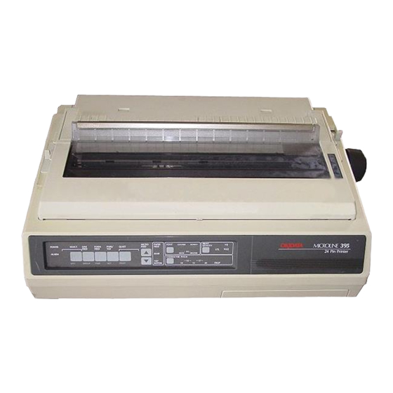
ML395 // ML395C
Dot Matrix Printers
Adobe Acrobat printable reference
copy of the OKIDATA Service Training Manual.
Service Guide ML395/395C
Chapter 0 About This Manual
09/17/97
Page: 1
Advertisement
Table of Contents
Troubleshooting

Related Manuals for OKIDATA ML395C


Summary of Contents for OKIDATA ML395C
- Page 1 300 dpi, which is ideal for printing, but does not view on most displays well. Copyright 1997, Okidata, Division of OKI America, Inc. All rights reserved. See the OKIDATA Business Partner Exchange (BPX) for any updates to this material. (http://bpx.okidata.com)
-
Page 2: Table Of Contents
Table of Contents Page Service Guide ML395/395C 0 About This Manual Front Cover ..Manual Copyright 1 Product Specifications 1.1 Overview - General Information 1.2 Product Specifications 1.3 Paper Specifications 1.4 Physical Specifications 1.5 Power Requirements 1.6 Environmental Conditions 1.7 Agency Approvals 1.8 Options 1.9 Consumables 1.10 Memory Specifications... - Page 3 Table of Contents Page ..3.2.05 Operator Panel Assembly ..3.2.06 Control Board (TFCB) ..3.2.07 Interface Connector Board (TFIF or LQPN) ..3.2.08 Printer Mechanism ..3.2.09 Platen Assembly ..3.2.10 Line Feed Motor ..3.2.11 Head Cable Assembly ..3.2.12 Sensor Board ..3.2.13 Ribbon Feed Assembly ..3.2.14 Space Motor Assembly ..3.2.15 Space Belt ..3.2.16 Cooling Fan...
- Page 4 Table of Contents Page ..3.3.07 Paper Park ..3.3.08 Forms Tear Off 3.4 Cleaning 3.5 Lubrication ..Lubrication Points (Monochrome and Color) ....Lubrication Points (Monochrome and Color) - Continued ....Lubrication Points (Monochrome and Color) - Continued ..Lubrication Points (Color) ..Lubrication Points (Options) 3.6 Shipping Instructions - Return For Service ..3.6.02 All Other Returns 4 Failure &...
- Page 5 Table of Contents Page ..RAP 10C: Serial Interface Problem ..RAP 10D: Data Receive Failure (Alarm Light Lit) ..RAP 11: Color Ribbon Shift Problem 4.8 Printer Tests ..4.8.02 Font Test ..4.8.03 Serial Interface - Loopback Test ..4.8.04 Hexadecimal Dump 4.9 Resistance Checks - General Information ..4.9.02 Printhead Resistance Check ..4.9.03 Line Feed Motor Resistance Check ..4.9.04 Space Motor Resistance Check...
- Page 6 Table of Contents Page ..B.2.14 Pull Tractor Assembly (Option) ..B.2.15 Bottom Tractor Feed Unit (Push) [BTF] (Option) ..B.2.16 BTF Pull-Up Roller Assembly (Option) ..B.2.17 Consumables ..B.2.18 Packing Materials ..B.2.19 Documentation...
-
Page 7: About This Manual
Mount Laurel, NJ 08054-3499 Okilink Login Name: Technical Training OKI is a registered trademark of Oki Electric Industry Company, Ltd.; marques deposee de Oki Electric Industry Company, Ltd.; marca registrada, Oki Electric Industry Company, Ltd. OKIDATA is a registered trademark of Oki Electric Industry Company, Ltd.; marques deposee de Oki Electric Industry Company, Ltd.;... -
Page 8: Overview - General Information
IBM Proprinter XL24 printers. The Microline 395C emulates the Epson LQ 2550, Epson LQ850/1050 or the IBM Proprinter XL24. Copyright 1997, Okidata, Division of OKI America, Inc. All rights reserved. See the OKIDATA Business Partner Exchange (BPX) for any updates to this material. (http://bpx.okidata.com) -
Page 9: Product Specifications
Page: 4 Service Guide ML395/395C Chapter 1 Product Specifications 1.2 PRODUCT SPECIFICATIONS 1.2.01 Paper Feed Method Built-in push tractor Friction feed 1.2.02 Paper Path Bottom Feed Rear Feed Top Feed 1.2.03 Printhead Type Staggered, 24 pin, stored energy printhead 1.2.04 Interface Methods Both are Standard Centronics Parallel Interface RS232-C Serial Interface... - Page 10 6.0 IPS (inches per second) slew rate @ gap 3+ 1.2.10 Paper Out Detection Printhead distance from edge of paper when End of Paper is detected Rear Feed: 5.8" Bottom Feed: 2.4" Copyright 1997, Okidata, Division of OKI America, Inc. All rights reserved. See the OKIDATA Business...
- Page 11 Partner Exchange (BPX) for any updates to this material. (http://bpx.okidata.com)
-
Page 12: Paper Specifications
1 - 4 (4 Part Form Maximum) 1.3.04 Maximum Thickness .014 inches (Rear Feed) .020 inches (Bottom Feed) Copyright 1997, Okidata, Division of OKI America, Inc. All rights reserved. See the OKIDATA Business Partner Exchange (BPX) for any updates to this material. (http://bpx.okidata.com) -
Page 13: Physical Specifications
1.4 PHYSICAL SPECIFICATIONS 1.4.01 Printer Dimensions Width: 16.42" Height: 7.09" Length: 22.44" 1.4.02 Printer Weight 37 lbs. Copyright 1997, Okidata, Division of OKI America, Inc. All rights reserved. See the OKIDATA Business Partner Exchange (BPX) for any updates to this material. (http://bpx.okidata.com) -
Page 14: Power Requirements
50/60 hz. +/-2% 1.5.02 Power Consumption During Self Test : 180 VA During Standby : 60 VA Copyright 1997, Okidata, Division of OKI America, Inc. All rights reserved. See the OKIDATA Business Partner Exchange (BPX) for any updates to this material. (http://bpx.okidata.com) -
Page 15: Environmental Conditions
1.6.02 Printer Noise Level (10 cpi - LQ Mode) Standard noise level: 58 dba Quite mode noise level: 56 dba Copyright 1997, Okidata, Division of OKI America, Inc. All rights reserved. See the OKIDATA Business Partner Exchange (BPX) for any updates to this material. (http://bpx.okidata.com) -
Page 16: Agency Approvals
1.7 AGENCY APPROVALS North America FCC Class B UL 1950 - D3 CSA 950 - D3 Copyright 1997, Okidata, Division of OKI America, Inc. All rights reserved. See the OKIDATA Business Partner Exchange (BPX) for any updates to this material. (http://bpx.okidata.com) -
Page 17: Options
NOTE: A Pull Tractor Assembly or Bottom Push Tractor must be used to feed labels. Copyright 1997, Okidata, Division of OKI America, Inc. All rights reserved. See the OKIDATA Business Partner Exchange (BPX) for any updates to this material. (http://bpx.okidata.com) -
Page 18: Consumables
Can be used in both the Microline 395 and Microline 395C. Ribbon Life 400K Characters at 10 cpi in LQ mode Copyright 1997, Okidata, Division of OKI America, Inc. All rights reserved. See the OKIDATA Business Partner Exchange (BPX) for any updates to this material. (http://bpx.okidata.com) -
Page 19: Memory Specifications
DLL Buffer = 22 Kbytes Command Buffer = 11 Kbytes 1.10.03 EEPROM Internal Control, Menu = 256 bits Copyright 1997, Okidata, Division of OKI America, Inc. All rights reserved. See the OKIDATA Business Partner Exchange (BPX) for any updates to this material. (http://bpx.okidata.com) - Page 20 Page: 13 Service Guide ML395/395C Chapter 1 Product Specifications...
- Page 25 Copyright 1997, Okidata, Division of OKI America, Inc. All rights reserved. See the OKIDATA Business Partner Exchange (BPX) for any updates to this material. (http://bpx.okidata.com)
-
Page 26: Principles Of Operation
Control Board is supplied by the power supply unit. The power to the other electrical parts is distributed via the connectors on the Control Board. Copyright 1997, Okidata, Division of OKI America, Inc. All rights reserved. See the OKIDATA Business Partner Exchange (BPX) for any updates to this material. (http://bpx.okidata.com) -
Page 27: Microprocessors (Mpus) And Peripheral Circuits
Page: 15 Service Guide ML395/395C Chapter 2 Principles of Operation 2.1.02 Microprocessors (MPUs) and Peripheral Circuits Microprocessors (Q16: 80C154HGS and Q11: 80C154VGS) The Microprocessors are the nucleus of the control circuit. The peripheral circuits operate under program control by these microprocessors. The Master MPU (Q16) controls the interface, code processing and the Slave MPU. -
Page 28: Interface Control
Printhead Drive Control Printhead Drive Correction Modifies the drive time under the following circumstances Correction for edge pin driving Correction for drive voltage fluctuations Correction for head gap setting Interface LSI (Q12: MSM60306) The MSM60306 is an external interface LSI and controls the following functions. Interface Control Controls both the parallel and serial interface functions Pin 4 of this LSI enables selection of the serial or parallel interface... - Page 29 Copyright 1997, Okidata, Division of OKI America, Inc. All rights reserved. See the OKIDATA Business Partner Exchange (BPX) for any updates to this material. (http://bpx.okidata.com)
- Page 30 BUSY, etc.), then turns the SELECT lamp ON to inform the host computer that the printer is ready to receive data. Copyright 1997, Okidata, Division of OKI America, Inc. All rights reserved. See the OKIDATA Business Partner Exchange (BPX) for any updates to this material. (http://bpx.okidata.com)
- Page 31 Page: 17 Service Guide ML395/395C Chapter 2 Principles of Operation 2.1.04 Interface Control The Microline 395 is capable of serial or parallel operation. The desired interface method is selected by sliding the interface cover to expose the desired connector. When this is done, the interface select switch is turned ON or OFF to inform the Interface Control LSI (Q12) of the selected interface.
- Page 32 TTL levels to RS232-C levels by the line driver (Q2) and sent to the serial interface connector. Copyright 1997, Okidata, Division of OKI America, Inc. All rights reserved. See the OKIDATA Business Partner Exchange (BPX) for any updates to this material. (http://bpx.okidata.com)
-
Page 33: Printhead Drive Circuit
An RC circuit also is used to compensate for the fluctuation of drive voltage (+38 vdc).2-1-04B.pcx Copyright 1997, Okidata, Division of OKI America, Inc. All rights reserved. See the OKIDATA Business Partner Exchange (BPX) for any updates to this material. (http://bpx.okidata.com) -
Page 34: Spacing Drive Circuit
MO LSI IPT signal for use in Dot Timing. Copyright 1997, Okidata, Division of OKI America, Inc. All rights reserved. See the OKIDATA Business Partner Exchange (BPX) for any updates to this material. (http://bpx.okidata.com) -
Page 35: Line Feed Circuit
The signals LFf1 through LFf4 establish the proper phase relationship for driving the motor. Copyright 1997, Okidata, Division of OKI America, Inc. All rights reserved. See the OKIDATA Business Partner Exchange (BPX) for any updates to this material. (http://bpx.okidata.com) -
Page 36: Alarm Circuits
The Slave MPU relays the switch status to the Master MPU. The Master MPU will halt printing at the completion of the current line and light the ALARM Lamp. Copyright 1997, Okidata, Division of OKI America, Inc. All rights reserved. See the OKIDATA Business Partner Exchange (BPX) for any updates to this material. (http://bpx.okidata.com) -
Page 37: Paper End Detection Circuit
When the printer detects an out of paper condition, the PE-N signal goes low, the printing is stopped and the ALARM LAMP is turned ON. Copyright 1997, Okidata, Division of OKI America, Inc. All rights reserved. See the OKIDATA Business Partner Exchange (BPX) for any updates to this material. (http://bpx.okidata.com) -
Page 38: Power Supply
Output from the Main Control Board upon detection of an overdrive condition in the printhead LF motor or bail/ribbon motor drive circuits. Copyright 1997, Okidata, Division of OKI America, Inc. All rights reserved. See the OKIDATA Business Partner Exchange (BPX) for any updates to this material. (http://bpx.okidata.com) -
Page 39: Mechanical Operation
Page: 24 Service Guide ML395/395C Chapter 2 Principles of Operation 2.2 MECHANICAL OPERATION 2.2.01 The Printhead Mechanism The Microline 395 uses a highly efficient stored energy type printhead. Power is not consumed until the printwires are activated, thereby extending the printhead life to approximately 200 million characters. The printhead uses 24 printwires (two columns of 12 wires each). - Page 40 Copyright 1997, Okidata, Division of OKI America, Inc. All rights reserved. See the OKIDATA Business Partner Exchange (BPX) for any updates to this material. (http://bpx.okidata.com)
-
Page 41: Spacing
The carriage is designed to move 1.6 inches when the servo motor performs one rotation. Copyright 1997, Okidata, Division of OKI America, Inc. All rights reserved. See the OKIDATA Business Partner Exchange (BPX) for any updates to this material. (http://bpx.okidata.com) -
Page 42: Ribbon Drive
Page: 26 Service Guide ML395/395C Chapter 2 Principles of Operation 2.2.03 Ribbon Drive The ribbon drive mechanism moves the ribbon in synchronization with the space motor operation. The ribbon drive mechanism consists of the following items. Ribbon Drive Assembly Ribbon Cartridge Ribbon Cartridge An endless ribbon with a single direction feed is used. - Page 43 Copyright 1997, Okidata, Division of OKI America, Inc. All rights reserved. See the OKIDATA Business Partner Exchange (BPX) for any updates to this material. (http://bpx.okidata.com)
-
Page 44: Paper Feed
Page: 27 Service Guide ML395/395C Chapter 2 Principles of Operation 2.2.04 Paper Feed Paper feeding is performed by turning the platen and the pin tractor, which is driven by the line feed pulse motor. The paper feed mechanism consists of the following items. Pulse Motor (with gears) Idler Gear Change Spring... - Page 45 At the same time, the release lever pushes the pressure rollers away from the platen, allowing paper to be fed by the tractors. Copyright 1997, Okidata, Division of OKI America, Inc. All rights reserved. See the OKIDATA Business Partner Exchange (BPX) for any updates to this material. (http://bpx.okidata.com)
-
Page 46: Paper-End Detection
Page: 28 Service Guide ML395/395C Chapter 2 Principles of Operation 2.2.05 Paper-End Detection Cut-Sheet Paper-End When the release lever is in the SHEET FEED position, the photosensor located in the paper pressure guide is active. If sheet paper is installed, the paper is detected by the sensor and the sensor is turned on. When the printer is out of sheet paper, the sensor is turned off indicating a paper-end condition. - Page 47 When rear feed paper is installed, pressure is placed on the microswitch, located in the left push tractor. Since the switch is turned ON, paper is detected. Copyright 1997, Okidata, Division of OKI America, Inc. All rights reserved. See the OKIDATA Business Partner Exchange (BPX) for any updates to this material. (http://bpx.okidata.com)
-
Page 48: Automatic Paper Loading
NOTE: If the paper does not advance after the line feed motor has fed the equivalent of 2.4 inches of paper, the Auto-Load process stops. This situation is treated like an ordinary paper-end condition. Copyright 1997, Okidata, Division of OKI America, Inc. All rights reserved. See the OKIDATA Business Partner Exchange (BPX) for any updates to this material. (http://bpx.okidata.com) -
Page 49: Paper Park
The paper will remain on the push tractor, but out of the printing path. Copyright 1997, Okidata, Division of OKI America, Inc. All rights reserved. See the OKIDATA Business Partner Exchange (BPX) for any updates to this material. (http://bpx.okidata.com) -
Page 50: Maintenance & Disassembly
Cleaning procedures must be performed correctly if high print quality is to be achieved. Copyright 1997, Okidata, Division of OKI America, Inc. All rights reserved. See the OKIDATA Business Partner Exchange (BPX) for any updates to this material. (http://bpx.okidata.com) -
Page 51: Maintenance Items
All-Purpose Cleaner Dow Corning Molycoat BR-2 or Molycoat ME-300L or equivalent Contact Kleen (Okidata P/N 51802301) Copyright 1997, Okidata, Division of OKI America, Inc. All rights reserved. See the OKIDATA Business Partner Exchange (BPX) for any updates to this material. (http://bpx.okidata.com) -
Page 52: Maintenance Precautions
9. Do not place printed circuit boards directly on conductive surfaces. 10. Follow the recommended procedures when replacing assemblies and units. Copyright 1997, Okidata, Division of OKI America, Inc. All rights reserved. See the OKIDATA Business Partner Exchange (BPX) for any updates to this material. (http://bpx.okidata.com) -
Page 53: Disassembly/Assembly Procedures - General Information
Page: 34 Service Guide ML395/395C Chapter 3 Maintenance & Disassembly 3.2 DISASSEMBLY/ASSEMBLY PROCEDURES General Information This section contains the printer disassembly procedures. Only the removal procedures are explained here. Reverse the procedure for the installation. At the bottom of each procedure is a listing of the parts covered in that procedure. The Okidata part number, item description, comment (RSPL, Option, Consumable) and cross-reference to Appendix B is provided for each part. - Page 54 NOTE: Refer to Appendix B (Illustrated Parts Listing) for the location of the printers major assemblies. Copyright 1997, Okidata, Division of OKI America, Inc. All rights reserved. See the OKIDATA Business Partner Exchange (BPX) for any updates to this material. (http://bpx.okidata.com)
-
Page 55: Preliminary Items Printhead
Page: 35 Service Guide ML395/395C Chapter 3 Maintenance & Disassembly 3.2.01 Preliminary Items Printhead WARNING: The printhead will be HOT immediately after printing. 1. Open the printer access cover. 2. Remove the ribbon cartridge (1). 3. Place the head gap adjusting lever (2) to the range 9 position. 4. - Page 56 Copyright 1997, Okidata, Division of OKI America, Inc. All rights reserved. See the OKIDATA Business Partner Exchange (BPX) for any updates to this material. (http://bpx.okidata.com)
-
Page 57: Ribbon Guide
3. Lift the ribbon guide (2) and remove it. P/N 53055901 Guide: Ribbon (Black) RSPL B.2.04 Copyright 1997, Okidata, Division of OKI America, Inc. All rights reserved. See the OKIDATA Business Partner Exchange (BPX) for any updates to this material. (http://bpx.okidata.com) -
Page 58: Ribbon Protector
4. Lift the ribbon protector (2) and remove it. P/N 53527001 Protector: Ribbon RSPL B.2.04 , 05 Copyright 1997, Okidata, Division of OKI America, Inc. All rights reserved. See the OKIDATA Business Partner Exchange (BPX) for any updates to this material. (http://bpx.okidata.com) -
Page 59: Upper Cover Assembly
P/N 50212441 Cover: Middle Assembly RSPL B.2.01 P/N 50212442 Cover: Middle Assembly RSPL B.2.01 (Color) P/N 50215701 Cover: Access (ML395) RSPL B.2.01 P/N 50215703 Cover: Access (ML395C) RSPL B.2.01 P/N 50215801 Cover: Rear Assembly RSPL B.2.01 P/N 53478601 Platen Knob RSPL B.2.02... - Page 60 Copyright 1997, Okidata, Division of OKI America, Inc. All rights reserved. See the OKIDATA Business Partner Exchange (BPX) for any updates to this material. (http://bpx.okidata.com)
-
Page 61: Operator Panel Assembly
Page: 39 Service Guide ML395/395C Chapter 3 Maintenance & Disassembly 3.2.05 Operator Panel Assembly Remove the upper cover assembly (3.2.04). 2. Disconnect the operator panel cable (1) from CN10 (2) on the control board. 3. Remove the two mounting screws (3). 4. - Page 62 Copyright 1997, Okidata, Division of OKI America, Inc. All rights reserved. See the OKIDATA Business Partner Exchange (BPX) for any updates to this material. (http://bpx.okidata.com)
-
Page 63: Control Board (Tfcb)
Page: 40 Service Guide ML395/395C Chapter 3 Maintenance & Disassembly 3.2.06 Control Board (TFCB) 1. Remove the upper cover assembly (3.2.04). 2. Remove the ribbon cartridge. 3. Release the lock of connector CN10 (1) and detach the operator panel cable (2). 4. - Page 64 Copyright 1997, Okidata, Division of OKI America, Inc. All rights reserved. See the OKIDATA Business Partner Exchange (BPX) for any updates to this material. (http://bpx.okidata.com)
- Page 65 Page: 41 Service Guide ML395/395C Chapter 3 Maintenance & Disassembly 3.2.07 Interface Connector Board (TFIF or LQPN) NOTE: To allow easier access to the mounting screw and cables, configure the interface connector board to use the serial interface connector. 1. Remove the upper cover assembly (3.2.04). 2.
- Page 66 Copyright 1997, Okidata, Division of OKI America, Inc. All rights reserved. See the OKIDATA Business Partner Exchange (BPX) for any updates to this material. (http://bpx.okidata.com)
- Page 67 Page: 42 Service Guide ML395/395C Chapter 3 Maintenance & Disassembly 3.2.08 Printer Mechanism 1. Remove the control board (3.2.06). 2. Detach connectors CN102 (1) and CN103 (2) from the interface connector board. 3. Remove the three mounting screws (3) at the rear of the printer mechanism (4). 4.
- Page 68 Copyright 1997, Okidata, Division of OKI America, Inc. All rights reserved. See the OKIDATA Business Partner Exchange (BPX) for any updates to this material. (http://bpx.okidata.com)
- Page 69 Page: 43 Service Guide ML395/395C Chapter 3 Maintenance & Disassembly 3.2.09 Platen Assembly 1. Remove the upper cover assembly (3.2.04). 2. Loosen the three 7 mm line feed motor mounting bolts (1). 3. Move the line feed motor (2) closer to the platen (3) and detach the line feed drive belt (4). 4.
- Page 70 Copyright 1997, Okidata, Division of OKI America, Inc. All rights reserved. See the OKIDATA Business Partner Exchange (BPX) for any updates to this material. (http://bpx.okidata.com)
-
Page 71: Line Feed Motor
P/N 56510601 Motor: Line Feed (ML395) RSPL B.2.06 , 09 Copyright 1997, Okidata, Division of OKI America, Inc. All rights reserved. See the OKIDATA Business Partner Exchange (BPX) for any updates to this material. (http://bpx.okidata.com) - Page 72 Page: 45 Service Guide ML395/395C Chapter 3 Maintenance & Disassembly 3.2.11 Head Cable Assembly 1. Detach the printhead (3.2.01). 2. Remove the printer mechanism (3.2.09). 3. Work from the bottom of the printer mechanism and loosen the two mounting screws (1). 4.
- Page 73 Copyright 1997, Okidata, Division of OKI America, Inc. All rights reserved. See the OKIDATA Business Partner Exchange (BPX) for any updates to this material. (http://bpx.okidata.com)
-
Page 74: Sensor Board
(LQEW or LPRW) P/N 56619104 Cord: Sensor PCB Connection RSPL B.2.06 , 09 , 12 Copyright 1997, Okidata, Division of OKI America, Inc. All rights reserved. See the OKIDATA Business Partner Exchange (BPX) for any updates to this material. (http://bpx.okidata.com) -
Page 75: Ribbon Feed Assembly
Page: 47 Service Guide ML395/395C Chapter 3 Maintenance & Disassembly 3.2.13 Ribbon Feed Assembly 1. Remove the printer mechanism (3.2.08). 2. Remove the two ribbon cartridge bracket mounting screws (1). 3. Detach the cartridge bracket (2). 4. Remove the two mounting screws (3). 5. - Page 76 Copyright 1997, Okidata, Division of OKI America, Inc. All rights reserved. See the OKIDATA Business Partner Exchange (BPX) for any updates to this material. (http://bpx.okidata.com)
-
Page 77: Space Motor Assembly
Page: 48 Service Guide ML395/395C Chapter 3 Maintenance & Disassembly 3.2.14 Space Motor Assembly 1. Remove the printhead (3.2.01). 2. Remove the ribbon feed assembly (3.2.13). 3. Loosen the two belt pulley bracket mounting screws (1). 4. While pushing the belt pulley bracket (2) to the left, temporarily tighten the two screws. This will ease the tension on the space belt. - Page 78 Copyright 1997, Okidata, Division of OKI America, Inc. All rights reserved. See the OKIDATA Business Partner Exchange (BPX) for any updates to this material. (http://bpx.okidata.com)
-
Page 79: Space Belt
Page: 49 Service Guide ML395/395C Chapter 3 Maintenance & Disassembly 3.2.15 Space Belt 1. Remove the printhead (3.2.01). 2. Remove the head cable assembly (3.2.11). 3. Remove the space motor assembly (3.2.14). 4. Remove the mounting screw (1). 5. Detach the belt clamp (2). 6. - Page 80 Copyright 1997, Okidata, Division of OKI America, Inc. All rights reserved. See the OKIDATA Business Partner Exchange (BPX) for any updates to this material. (http://bpx.okidata.com)
-
Page 81: Cooling Fan
Page: 50 Service Guide ML395/395C Chapter 3 Maintenance & Disassembly 3.2.16 Cooling Fan 1. Remove the printer mechanism (3.2.08). 2. Remove the two ribbon cartridge bracket mounting screws (1). 3. Detach the cartridge bracket (2). 4. Using needle-nosed pliers, detach the nylon cable clamp (3) from the fan cover (4). 5. - Page 82 Copyright 1997, Okidata, Division of OKI America, Inc. All rights reserved. See the OKIDATA Business Partner Exchange (BPX) for any updates to this material. (http://bpx.okidata.com)
-
Page 83: Bail/Ribbon Motor Assembly
P/N 56506301 Motor: Step (Bail Arm) Assembly RSPL B.2.06 , 09 Copyright 1997, Okidata, Division of OKI America, Inc. All rights reserved. See the OKIDATA Business Partner Exchange (BPX) for any updates to this material. (http://bpx.okidata.com) -
Page 84: Paper Bail Assembly
Page: 52 Service Guide ML395/395C Chapter 3 Maintenance & Disassembly 3.2.18 Paper Bail Assembly 1. Remove the printer mechanism (3.2.08). 2. Remove the bail/ribbon motor assembly (3.2.17). 3. Detach the bail arm springs (1). NOTE: The left bail arm spring is longer than the right bail arm spring. Be sure to install each spring on the proper side. - Page 85 Copyright 1997, Okidata, Division of OKI America, Inc. All rights reserved. See the OKIDATA Business Partner Exchange (BPX) for any updates to this material. (http://bpx.okidata.com)
-
Page 86: Carriage And Carriage Shaft
Page: 53 Service Guide ML395/395C Chapter 3 Maintenance & Disassembly 3.2.19 Carriage and Carriage Shaft 1. Loosen the screw (1) and slide it towards the back of the printer. 2. Loosen the mounting screw (2) and detach the left eccentric collar (3). NOTE: The protrusions on the eccentric collars face the outside of the printer. - Page 87 Copyright 1997, Okidata, Division of OKI America, Inc. All rights reserved. See the OKIDATA Business Partner Exchange (BPX) for any updates to this material. (http://bpx.okidata.com)
-
Page 88: Paper Pressure Guide
Page: 54 Service Guide ML395/395C Chapter 3 Maintenance & Disassembly 3.2.20 Paper Pressure Guide 1. Remove the two springs (1) located on each side of the paper pressure guide (2). 2. Remove the detent spring (3) located on the release lever at the right side of the printer. 3. - Page 89 Copyright 1997, Okidata, Division of OKI America, Inc. All rights reserved. See the OKIDATA Business Partner Exchange (BPX) for any updates to this material. (http://bpx.okidata.com)
-
Page 90: Printhead Gap / Release Lever Microswitches
P/N 53068602 Indicator: PH Gap (Adj Bracket) RSPL B.2.07 , 11 P/N 56209901 Switch: Micro RSPL B.2.07 , 11 (Adj & Release Lever) Copyright 1997, Okidata, Division of OKI America, Inc. All rights reserved. See the OKIDATA Business Partner Exchange (BPX) for any updates to this material. (http://bpx.okidata.com) -
Page 91: Push Tractor Assembly
Page: 56 Service Guide ML395/395C Chapter 3 Maintenance & Disassembly 3.2.22 Push Tractor Assembly 1. Remove the lower center guide (1). 2. Separate the claws (2) and remove the two drive gears (3) from the right side of the printer mechanism. 3. - Page 92 P/N 51214201 Gear: Drive A RSPL B.2.08 , 11 P/N 51214301 Gear: Drive B RSPL B.2.08 , 11 Copyright 1997, Okidata, Division of OKI America, Inc. All rights reserved. See the OKIDATA Business Partner Exchange (BPX) for any updates to this material. (http://bpx.okidata.com)
-
Page 93: Power Supply Unit
Page: 57 Service Guide ML395/395C Chapter 3 Maintenance & Disassembly 3.2.23 Power Supply Unit 1. Remove the printer mechanism (3.2.08). 2. Disconnect the two cables (1) from the left side of the power supply unit (2). 3. Remove the four power supply mounting screws (3). 4. - Page 94 Copyright 1997, Okidata, Division of OKI America, Inc. All rights reserved. See the OKIDATA Business Partner Exchange (BPX) for any updates to this material. (http://bpx.okidata.com)
-
Page 95: Ribbon Shift Arm Spring / Ribbon Shift Arm
Page: 58 Service Guide ML395/395C Chapter 3 Maintenance & Disassembly 3.2.24 Ribbon Shift Arm Spring / Ribbon Shift Arm Microline 395C - Color Model Only 1. Detach the printer access cover. 2. Remove the ribbon cartridge (1). 3. Remove the shift arm spring (2). 4. - Page 96 Copyright 1997, Okidata, Division of OKI America, Inc. All rights reserved. See the OKIDATA Business Partner Exchange (BPX) for any updates to this material. (http://bpx.okidata.com)
-
Page 97: Roller Lever
Page: 59 Service Guide ML395/395C Chapter 3 Maintenance & Disassembly 3.2.25 Roller Lever 1. Open the printer access cover. 2. Remove the ribbon cartridge. 3. Remove the shift arm spring (3.2.23). 4. Remove the two 7 mm bolts (1) and detach the roller lever (2). P/N 53479001 Lever: Roller (Color) RSPL B.2.05... - Page 98 Copyright 1997, Okidata, Division of OKI America, Inc. All rights reserved. See the OKIDATA Business Partner Exchange (BPX) for any updates to this material. (http://bpx.okidata.com)
-
Page 99: Ribbon Guide
Page: 60 Service Guide ML395/395C Chapter 3 Maintenance & Disassembly 3.2.26 Ribbon Guide 1. Remove the printhead (3.2.01). 2. Loosen the 7 mm ribbon shift arm mounting bolt (1) and detach the ribbon shift arm (2) from projection A of the ribbon guide (3). 3. - Page 101 Copyright 1997, Okidata, Division of OKI America, Inc. All rights reserved. See the OKIDATA Business Partner Exchange (BPX) for any updates to this material. (http://bpx.okidata.com)
-
Page 102: Bail Open Cam And Bail Open Gear
Page: 61 Service Guide ML395/395C Chapter 3 Maintenance & Disassembly 3.2.27 Bail Open Cam and Bail Open Gear 1. Remove the printer mechanism (3.2.08). 2. Detach the E snap ring (1). 3. Remove the bail open gear (2). 4. Remove the bail open cam (3). 5. - Page 103 Copyright 1997, Okidata, Division of OKI America, Inc. All rights reserved. See the OKIDATA Business Partner Exchange (BPX) for any updates to this material. (http://bpx.okidata.com)
-
Page 104: Ribbon Shift Cam And Ribbon Shift Gear
Page: 62 Service Guide ML395/395C Chapter 3 Maintenance & Disassembly 3.2.28 Ribbon Shift Cam and Ribbon Shift Gear 1. Remove the printer mechanism (3.2.08). 2. Detach the E snap ring (1). 3. Remove the ribbon shift gear (2). 4. Remove the washer. 5. - Page 105 Copyright 1997, Okidata, Division of OKI America, Inc. All rights reserved. See the OKIDATA Business Partner Exchange (BPX) for any updates to this material. (http://bpx.okidata.com)
-
Page 106: Ribbon Shift Cam Lever Assembly
Page: 63 Service Guide ML395/395C Chapter 3 Maintenance & Disassembly 3.2.29 Ribbon Shift Cam Lever Assembly 1. Remove the printer mechanism (3.2.08). 2. Remove the ribbon shift cam and ribbon shift gear (3.2.27). 3. Remove the mounting screw (1) 4. Detach the ribbon shift cam lever (2) from the cartridge bracket (3). NOTE: After assembly, perform the Microline 395C color adjustment (3.3.03). - Page 107 Copyright 1997, Okidata, Division of OKI America, Inc. All rights reserved. See the OKIDATA Business Partner Exchange (BPX) for any updates to this material. (http://bpx.okidata.com)
-
Page 108: Printer Unit
Page: 64 Service Guide ML395/395C Chapter 3 Maintenance & Disassembly 3.2.30 Printer Unit Bottom Push Tractor Unit (Optional) 1. Turn the power switch OFF and remove the AC power cord from the outlet. 2. Remove the DIN connector (1). 3. Lift the printer unit (2) from the bottom push tractor unit (3). - Page 109 Copyright 1997, Okidata, Division of OKI America, Inc. All rights reserved. See the OKIDATA Business Partner Exchange (BPX) for any updates to this material. (http://bpx.okidata.com)
-
Page 110: Btfd Printed Circuit Board
3. Remove the two mounting screws (3) 4. Detach the BTFD board. P/N 55066102 PCB: BTFD-2 (BTF) Option RSPL B.2.15 Copyright 1997, Okidata, Division of OKI America, Inc. All rights reserved. See the OKIDATA Business Partner Exchange (BPX) for any updates to this material. (http://bpx.okidata.com) -
Page 111: Tension Spring
2. Detach the tension spring (1) from between the bottom cover (2) and the blind plate (3). P/N 50922001 Spring: (BTF) Option RSPL B.2.15 Copyright 1997, Okidata, Division of OKI America, Inc. All rights reserved. See the OKIDATA Business Partner Exchange (BPX) for any updates to this material. (http://bpx.okidata.com) -
Page 112: Sheet Guide
1. Remove the printer unit (3.2.30). 2. Remove the sheet guide (1). P/N 51002201 Guide: Sheet (BTF) Option RSPL B.2.15 Copyright 1997, Okidata, Division of OKI America, Inc. All rights reserved. See the OKIDATA Business Partner Exchange (BPX) for any updates to this material. (http://bpx.okidata.com) -
Page 113: Btf Front Door Assembly
Page: 68 Service Guide ML395/395C Chapter 3 Maintenance & Disassembly 3.2.34 BTF Front Door Assembly 1. Remove the printer unit (3.2.30). 2. Detach connector CN1 (1) from the BTFD board (2). 3. Remove the tension spring (3.2.32). 4. Remove the four mounting screws (3). 5. - Page 114 Copyright 1997, Okidata, Division of OKI America, Inc. All rights reserved. See the OKIDATA Business Partner Exchange (BPX) for any updates to this material. (http://bpx.okidata.com)
-
Page 115: Drive Pulley And Mini-Pitch Belt
P/N 51228801 Pulley: Drive (BTF) (ML395) Option RSPL B.2.15 P/N 54111291 Belt: Mini Pitch (125 teeth) Option RSPL B.2.15 Copyright 1997, Okidata, Division of OKI America, Inc. All rights reserved. See the OKIDATA Business Partner Exchange (BPX) for any updates to this material. (http://bpx.okidata.com) -
Page 116: Line Feed Motor
5. Detach the line feed motor (3). P/N 56509401 Motor: Line Feed (BTF) Option RSPL B.2.15 Copyright 1997, Okidata, Division of OKI America, Inc. All rights reserved. See the OKIDATA Business Partner Exchange (BPX) for any updates to this material. (http://bpx.okidata.com) -
Page 117: Tractor Assembly
Page: 71 Service Guide ML395/395C Chapter 3 Maintenance & Disassembly 3.2.37 Tractor Assembly 1. Remove the printer unit (3.2.30). 2. Remove the bottom push mechanism (3.2.34 - Steps 2,3,4,5). 3. Remove the screw (1), the balancer (2), and the E-clip (3). 4. - Page 118 Copyright 1997, Okidata, Division of OKI America, Inc. All rights reserved. See the OKIDATA Business Partner Exchange (BPX) for any updates to this material. (http://bpx.okidata.com)
- Page 119 Page: 72 Service Guide ML395/395C Chapter 3 Maintenance & Disassembly 3.3 PRINTER ADJUSTMENTS 3.3.01 Printhead Gap 1. Remove the printhead (3.2.01). 2. Remove the ribbon guide (3.2.02). 3. Remove the ribbon protector (3.2.03). 4. Install the printhead. 5. Set the printhead gap lever to position 1. 6.
- Page 120 Copyright 1997, Okidata, Division of OKI America, Inc. All rights reserved. See the OKIDATA Business Partner Exchange (BPX) for any updates to this material. (http://bpx.okidata.com)
-
Page 121: Line Feed Belt Tension
3. Adjust the line feed motor (2) position to obtain a 1/16 inch deflection at point B. 4. Tighten the three mounting bolts. Copyright 1997, Okidata, Division of OKI America, Inc. All rights reserved. See the OKIDATA Business Partner Exchange (BPX) for any updates to this material. (http://bpx.okidata.com) -
Page 122: Color Adjustment (Microline 395C Printer)
6. Check that the ribbon guide remained at the top of the post. If it moved, repeat the procedure. Copyright 1997, Okidata, Division of OKI America, Inc. All rights reserved. See the OKIDATA Business Partner Exchange (BPX) for any updates to this material. (http://bpx.okidata.com) -
Page 123: Key Combinations
PARK (Hold during power ON) Activate Rolling ASCII Test To end Rolling ASCII Test press SELECT Copyright 1997, Okidata, Division of OKI America, Inc. All rights reserved. See the OKIDATA Business Partner Exchange (BPX) for any updates to this material. (http://bpx.okidata.com) -
Page 124: Menu Operation - Menu Mode
A line prints, showing the Setting. Press EXIT to exit Menu Mode. The printer will go ON-LINE. (SELECT will light.) Copyright 1997, Okidata, Division of OKI America, Inc. All rights reserved. See the OKIDATA Business Partner Exchange (BPX) for any updates to this material. (http://bpx.okidata.com) -
Page 125: Menu Print
7. Press EXIT to exit Menu Mode. 8. The printer will go ON-LINE. (SELECT will light.) Copyright 1997, Okidata, Division of OKI America, Inc. All rights reserved. See the OKIDATA Business Partner Exchange (BPX) for any updates to this material. (http://bpx.okidata.com) -
Page 126: Sample Menu
Page: 78 Service Guide ML395/395C Chapter 3 Maintenance & Disassembly Sample Menu Copyright 1997, Okidata, Division of OKI America, Inc. All rights reserved. See the OKIDATA Business Partner Exchange (BPX) for any updates to this material. (http://bpx.okidata.com) -
Page 127: Menu Settings
Page: 79 Service Guide ML395/395C Chapter 3 Maintenance & Disassembly Menu Settings Factory default settings are printed in Bold Italic . Group Item Setting Printer Control Emulation Mode Epson LQ IBM PPR IBM X24 AGM Font Print Mode LQ NLQ Utility HSD Typestyle Courier Roman Swiss Orator DLL Pitch... - Page 128 Auto CR (IBM emulation No Yes only) Form Tear-Off Off 300 mS 2 sec 4 sec Menu Line Factory default settings are printed in Bold Italic . Group Item Setting Rear Feed Line Spacing 6 LPI 8 LPI Skip Over Perforation No Yes Page Length 12"...
- Page 129 DTR Signal Ready on Power UP Ready on Select Busy Time 200 mS 1 sec Copyright 1997, Okidata, Division of OKI America, Inc. All rights reserved. See the OKIDATA Business Partner Exchange (BPX) for any updates to this material. (http://bpx.okidata.com)
- Page 130 3. Press SELECT and PARK while powering ON the printer. 4. The Menu is reset to Factory Defaults. Copyright 1997, Okidata, Division of OKI America, Inc. All rights reserved. See the OKIDATA Business Partner Exchange (BPX) for any updates to this material. (http://bpx.okidata.com)
- Page 131 7. Press EXIT to exit Menu Mode. 8. The printer will go ON-LINE. (SELECT will light.) Copyright 1997, Okidata, Division of OKI America, Inc. All rights reserved. See the OKIDATA Business Partner Exchange (BPX) for any updates to this material. (http://bpx.okidata.com)
-
Page 132: Top Of Form
Page: 82 Service Guide ML395/395C Chapter 3 Maintenance & Disassembly 3.3.06 Top of Form General Information Top of form is the place on the page where printing begins. When the printer advances paper to the next page, it stops at the top of form. The Microline 395 and 395C printers store the top of form independently for the three standard paper feed paths. - Page 133 Copyright 1997, Okidata, Division of OKI America, Inc. All rights reserved. See the OKIDATA Business Partner Exchange (BPX) for any updates to this material. (http://bpx.okidata.com)
-
Page 134: Paper Park
3. The paper will advance to the loading position. 4. Push the bail lever back and adjust the top of form (if necessary). Copyright 1997, Okidata, Division of OKI America, Inc. All rights reserved. See the OKIDATA Business Partner Exchange (BPX) for any updates to this material. (http://bpx.okidata.com) -
Page 135: Forms Tear Off
Page: 84 Service Guide ML395/395C Chapter 3 Maintenance & Disassembly 3.3.08 Forms Tear Off General Information This feature (when activated) will automatically advance continuous feed paper to the tear-off position after it finishes printing the last page in the document. A few seconds after the printing stops, the printer will move the paper up to the tear-off position, aligning the perforation with the serrated edge on the access cover. - Page 136 The paper will then be retracted to the next print position. Copyright 1997, Okidata, Division of OKI America, Inc. All rights reserved. See the OKIDATA Business Partner Exchange (BPX) for any updates to this material. (http://bpx.okidata.com)
-
Page 137: Cleaning
Page: 85 Service Guide ML395/395C Chapter 3 Maintenance & Disassembly 3.4 CLEANING 3.4.01 General Information WARNING When cleaning the printer, power OFF the printer and detach the AC power cable from the printer and the AC outlet. Cleaning Interval Every six months or 300 hours of operation Cleaning Tools Lint free cloth Soft cloth... - Page 138 Copyright 1997, Okidata, Division of OKI America, Inc. All rights reserved. See the OKIDATA Business Partner Exchange (BPX) for any updates to this material. (http://bpx.okidata.com)
- Page 139 Page: 86 Service Guide ML395/395C Chapter 3 Maintenance & Disassembly 3.5 LUBRICATION 3.5.01 General Information When lubricating the printer, refer to the lubrication diagrams on the following pages. Each lubrication point lists a code for the type of lubricant to be used along with a code for the amount of lubricant required. These codes are defined below.
- Page 140 Copyright 1997, Okidata, Division of OKI America, Inc. All rights reserved. See the OKIDATA Business Partner Exchange (BPX) for any updates to this material. (http://bpx.okidata.com)
-
Page 141: Lubrication
Page: 87 Service Guide ML395/395C Chapter 3 Maintenance & Disassembly Lubrication Points (Monochrome and Color) - Page 142 Copyright 1997, Okidata, Division of OKI America, Inc. All rights reserved. See the OKIDATA Business Partner Exchange (BPX) for any updates to this material. (http://bpx.okidata.com)
-
Page 143: Lubrication Points (Monochrome And Color)
Page: 88 Service Guide ML395/395C Chapter 3 Maintenance & Disassembly Lubrication Points (Monochrome and Color) Copyright 1997, Okidata, Division of OKI America, Inc. All rights reserved. See the OKIDATA Business Partner Exchange (BPX) for any updates to this material. (http://bpx.okidata.com) -
Page 144: Lubrication Points (Monochrome And Color)
Page: 89 Service Guide ML395/395C Chapter 3 Maintenance & Disassembly Lubrication Points (Monochrome and Color) - Page 145 Copyright 1997, Okidata, Division of OKI America, Inc. All rights reserved. See the OKIDATA Business Partner Exchange (BPX) for any updates to this material. (http://bpx.okidata.com)
-
Page 146: Lubrication Points (Color)
Page: 90 Service Guide ML395/395C Chapter 3 Maintenance & Disassembly Lubrication Points (Color) - Page 147 Copyright 1997, Okidata, Division of OKI America, Inc. All rights reserved. See the OKIDATA Business Partner Exchange (BPX) for any updates to this material. (http://bpx.okidata.com)
-
Page 148: Lubrication Points (Options)
Page: 91 Service Guide ML395/395C Chapter 3 Maintenance & Disassembly Lubrication Points (Options) Copyright 1997, Okidata, Division of OKI America, Inc. All rights reserved. See the OKIDATA Business... - Page 149 Partner Exchange (BPX) for any updates to this material. (http://bpx.okidata.com)
- Page 150 3. Remove the platen knob. Be sure to place it in the shipping container. 4. Pack the unit, using the materials from Step 1. Copyright 1997, Okidata, Division of OKI America, Inc. All rights reserved. See the OKIDATA Business Partner Exchange (BPX) for any updates to this material. (http://bpx.okidata.com)
-
Page 151: All Other Returns
3. Make sure the printhead is secured so it will not move during shipment. 4. Pack the unit, using the materials from Step 1. Copyright 1997, Okidata, Division of OKI America, Inc. All rights reserved. See the OKIDATA Business Partner Exchange (BPX) for any updates to this material. (http://bpx.okidata.com) -
Page 152: Failure & Repair Analysis
Okidata, using one of the methods listed. Refer to the Service Center Reference Guide for information on contacting Okidata. Copyright 1997, Okidata, Division of OKI America, Inc. All rights reserved. See the OKIDATA Business Partner Exchange (BPX) for any updates to this material. (http://bpx.okidata.com) -
Page 153: Printer Serial Number Identification
Example Printer Serial Number: 401A0154693 Date Code 401 (4 = year. 01 = month) Revision A Serial Number 0154693 Copyright 1997, Okidata, Division of OKI America, Inc. All rights reserved. See the OKIDATA Business Partner Exchange (BPX) for any updates to this material. (http://bpx.okidata.com) -
Page 154: Reporting Problems - General Information
Okidata know. Refer to the Service Center Reference Guide for information on contacting Okidata. Copyright 1997, Okidata, Division of OKI America, Inc. All rights reserved. See the OKIDATA Business Partner Exchange (BPX) for any updates to this material. (http://bpx.okidata.com) -
Page 155: Problem Lists
Okidata can provide the best possible information. Your cooperation is greatly appreciated. Thank you for your help! Copyright 1997, Okidata, Division of OKI America, Inc. All rights reserved. See the OKIDATA Business Partner Exchange (BPX) for any updates to this material. (http://bpx.okidata.com) -
Page 156: Reporting Methods
Firmware Revision Level Description of Problem Document Name (with page number or procedure) with error or problem. Copyright 1997, Okidata, Division of OKI America, Inc. All rights reserved. See the OKIDATA Business Partner Exchange (BPX) for any updates to this material. (http://bpx.okidata.com) -
Page 157: Troubleshooting Updates - General Information
Okidata distributes updated troubleshooting information in three ways. Okilink II Faxable Facts Technical Service Bulletins Copyright 1997, Okidata, Division of OKI America, Inc. All rights reserved. See the OKIDATA Business Partner Exchange (BPX) for any updates to this material. (http://bpx.okidata.com) - Page 158 Drivers, Product Specifications, and Service Training Information are also available. Refer to the Service Center Reference Guide for information on accessing Okilink II. Copyright 1997, Okidata, Division of OKI America, Inc. All rights reserved. See the OKIDATA Business Partner Exchange (BPX) for any updates to this material. (http://bpx.okidata.com)
- Page 159 Faxable Facts. Refer to the Service Center Reference Guide for information on accessing Faxable Facts. Copyright 1997, Okidata, Division of OKI America, Inc. All rights reserved. See the OKIDATA Business Partner Exchange (BPX) for any updates to this material. (http://bpx.okidata.com)
-
Page 160: Technical Service Bulletins
The TSBs are distributed through Okilink II. Refer to the Service Center Reference Guide for information on accessing Okilink II. Copyright 1997, Okidata, Division of OKI America, Inc. All rights reserved. See the OKIDATA Business Partner Exchange (BPX) for any updates to this material. (http://bpx.okidata.com) -
Page 161: Troubleshooting Tips - Preliminary Checks
4. Has the ribbon been installed properly? 5. Is an Okidata ribbon being used? 6. Is the printhead gap correctly set? Copyright 1997, Okidata, Division of OKI America, Inc. All rights reserved. See the OKIDATA Business Partner Exchange (BPX) for any updates to this material. (http://bpx.okidata.com) -
Page 162: Problem Categories
A solid ALARM Lamp usually indicates a paper jam or paper-end (out of paper) condition. Copyright 1997, Okidata, Division of OKI America, Inc. All rights reserved. See the OKIDATA Business Partner Exchange (BPX) for any updates to this material. (http://bpx.okidata.com) -
Page 163: Start Here Flowchart
Refer to Section 4.6 NO The problem occurs during printing. Refer to the RAP Index - Section 4.7 Copyright 1997, Okidata, Division of OKI America, Inc. All rights reserved. See the OKIDATA Business Partner Exchange (BPX) for any updates to this material. (http://bpx.okidata.com) -
Page 164: Tips For Preventing Image Problems
3. Always place the Head Gap Lever in the position appropriate for the paper that you are using. Copyright 1997, Okidata, Division of OKI America, Inc. All rights reserved. See the OKIDATA Business Partner Exchange (BPX) for any updates to this material. (http://bpx.okidata.com) -
Page 165: Common Problems
Page: 107 Service Guide ML395/395C Chapter 4 Failure & Repair Analysis 4.4.05 Common Problems 1. Nothing happens when the printer is powered ON. Make sure the printer is plugged in. Check the power cord connection to the printer and the outlet. If a power strip is being used, make sure the strip is powered ON. - Page 166 for a previous job. The codes will override panel or menu settings. Check the word processors manual to see if the initialization string can be modified. If so, remove any codes that interfere with the printers settings. To set the printer to ignore the reset code, follow this procedure. 1.
- Page 167 Follow the normal menu procedures to set the Operator Panel Functions Item to FULL OPERATION. Copyright 1997, Okidata, Division of OKI America, Inc. All rights reserved. See the OKIDATA Business Partner Exchange (BPX) for any updates to this material. (http://bpx.okidata.com)
-
Page 168: Abnormal Output
Page: 108 Service Guide ML395/395C Chapter 4 Failure & Repair Analysis 4.5 ABNORMAL OUTPUT 4.5.01 Output Samples Light Print on the Entire Page Possible Causes:... - Page 169 2. Make sure that the space belt tension is within specification. If it is not, tighten the belt. Copyright 1997, Okidata, Division of OKI America, Inc. All rights reserved. See the OKIDATA Business Partner Exchange (BPX) for any updates to this material. (http://bpx.okidata.com)
-
Page 170: Fault Alarms - General Information
Page: 109 Service Guide ML395/395C Chapter 4 Failure & Repair Analysis 4.6 FAULT ALARMS 4.6.01 General Information When an error condition exists, the ALARM LAMP will flash. The operator panel is used to display printer error conditions. The type of error condition can be determined by decoding the operator panel lamps. Refer to the Alarm Codes Table in this section to identify both the error condition and the recommended corrective action for each condition. - Page 171 Slave CPU Replace Watchdog controller Timer Error board Replace External RAM controller Error board Switch Mode Replace Compare controller Error board Command Replace FIFO Check controller Error board Replace Command controller Error board Print Bus Replace Error controller board Position Replace Sense Error controller...
- Page 172 See RAP 05 Fan Alarm Replace Power Supply Bottom Feed Check Connection Bottom Feed Error Unit Copyright 1997, Okidata, Division of OKI America, Inc. All rights reserved. See the OKIDATA Business Partner Exchange (BPX) for any updates to this material. (http://bpx.okidata.com)
- Page 173 4. All RAPs begin with a START statement, followed by questions or another type of statement. Copyright 1997, Okidata, Division of OKI America, Inc. All rights reserved. See the OKIDATA Business Partner Exchange (BPX) for any updates to this material. (http://bpx.okidata.com)
-
Page 174: Rap Index
Parallel Interface Problem Serial Interface Problem Data Receive Problem Alarm Light Lit Color Ribbon Shift Problems Copyright 1997, Okidata, Division of OKI America, Inc. All rights reserved. See the OKIDATA Business Partner Exchange (BPX) for any updates to this material. (http://bpx.okidata.com) -
Page 175: Rap 01: Power Lamp Does Not Light
YES Replace the control board. Has the problem been resolved? NO Contact Okidata Technical Support. YES End of procedure. Copyright 1997, Okidata, Division of OKI America, Inc. All rights reserved. See the OKIDATA Business Partner Exchange (BPX) for any updates to this material. (http://bpx.okidata.com) -
Page 176: Rap 02: Space Error (Alarm 5B)
Page: 113 Service Guide ML395/395C Chapter 4 Failure & Repair Analysis RAP 02: Space Error (ALARM 5B) START Is the carriage assembly binding or jammed? YES Check around the space motor mechanism for any obstructions. Then, remove the cause of the carriage jam. - Page 177 Has the problem been resolved? YES End of procedure. NO Replace the space motor. Copyright 1997, Okidata, Division of OKI America, Inc. All rights reserved. See the OKIDATA Business Partner Exchange (BPX) for any updates to this material. (http://bpx.okidata.com)
-
Page 178: Rap 03: Head Homing Error (Alarm 53)
NO Replace the space motor. Has the problem been resolved? YES End of procedure. NO Contact Okidata Technical Support. Copyright 1997, Okidata, Division of OKI America, Inc. All rights reserved. See the OKIDATA Business Partner Exchange (BPX) for any updates to this material. (http://bpx.okidata.com) -
Page 179: Rap 04: Ribbon Homing Error (Alarm 57)
Page: 115 Service Guide ML395/395C Chapter 4 Failure & Repair Analysis RAP 04: Ribbon Homing Error (ALARM 57) START Is the printer the color model? NO Is shorting plug SP3 of the control board open? NO Set it open. YES Go to A. YES Manually rotate the ribbon shift cam counterclockwise. - Page 180 NO Replace the sensor board. Copyright 1997, Okidata, Division of OKI America, Inc. All rights reserved. See the OKIDATA Business Partner Exchange (BPX) for any updates to this material. (http://bpx.okidata.com)
-
Page 181: Rap 05: Bail Home Error (Alarm 5C)
NO Replace the sensor board. Has the problem been resolved? YES End of procedure. NO Replace the bail/ribbon motor. Copyright 1997, Okidata, Division of OKI America, Inc. All rights reserved. See the OKIDATA Business Partner Exchange (BPX) for any updates to this material. (http://bpx.okidata.com) -
Page 182: Rap 06: Wrong Character, Character Omission, Or Dot
Page: 117 Service Guide ML395/395C Chapter 4 Failure & Repair Analysis RAP 06: Wrong Character, Character Omission, or Dot Omission START Are cables CN2 and CN6 on the control board connected correctly? NO Connect them correctly. YES Is cable CN101 on the interface connector board connected correctly? NO Connect it correctly. - Page 183 NO Check the MENU Settings related to the interface. Baud Rate Character Format Protocol BUSY Signal output selection Copyright 1997, Okidata, Division of OKI America, Inc. All rights reserved. See the OKIDATA Business Partner Exchange (BPX) for any updates to this material. (http://bpx.okidata.com)
-
Page 184: Rap 07: Ribbon Feed Trouble
YES Check that the ribbon feed shaft is correctly engaged with the ribbon feed roller of the ribbon cartridge. Copyright 1997, Okidata, Division of OKI America, Inc. All rights reserved. See the OKIDATA Business Partner Exchange (BPX) for any updates to this material. (http://bpx.okidata.com) -
Page 185: Rap 08: Line Feed Trouble
NO Replace the line feed motor. After replacing the line feed motor, adjust the belt tension. Copyright 1997, Okidata, Division of OKI America, Inc. All rights reserved. See the OKIDATA Business Partner Exchange (BPX) for any updates to this material. (http://bpx.okidata.com) -
Page 186: Rap 09: Malfunction Of Operator Panel Switch
YES Replace the operator panel. Has the problem been resolved? YES End of procedure. NO Replace the control board. Copyright 1997, Okidata, Division of OKI America, Inc. All rights reserved. See the OKIDATA Business Partner Exchange (BPX) for any updates to this material. (http://bpx.okidata.com) -
Page 187: Rap 10A: Data Receive Failure
YES Are you using a parallel interface? YES Refer to RAP 10B. NO Refer to RAP 10C. Copyright 1997, Okidata, Division of OKI America, Inc. All rights reserved. See the OKIDATA Business Partner Exchange (BPX) for any updates to this material. (http://bpx.okidata.com) -
Page 188: Rap 10B: Parallel Interface Problem
1. Replace the interface connector board. 2. Replace the cable connected to CN6 on the control board. Copyright 1997, Okidata, Division of OKI America, Inc. All rights reserved. See the OKIDATA Business Partner Exchange (BPX) for any updates to this material. (http://bpx.okidata.com) -
Page 189: Rap 10C: Serial Interface Problem
1. Replace the interface connector board. 2. Replace the cable connected to CN6 on the control board. Copyright 1997, Okidata, Division of OKI America, Inc. All rights reserved. See the OKIDATA Business Partner Exchange (BPX) for any updates to this material. (http://bpx.okidata.com) -
Page 190: Rap 10D: Data Receive Failure (Alarm Light Lit)
Page: 124 Service Guide ML395/395C Chapter 4 Failure & Repair Analysis RAP 10D: Data Receive Failure (Alarm Light Lit) START Remove the upper cover. Press and hold the cover open microswitch while powering ON the printer. Does the alarm lamp come on? NO Perform the operations listed below. - Page 191 YES Replace the control board. Has the problem been resolved? YES End of procedure. NO Contact Okidata Technical Support. Copyright 1997, Okidata, Division of OKI America, Inc. All rights reserved. See the OKIDATA Business Partner Exchange (BPX) for any updates to this material. (http://bpx.okidata.com)
-
Page 192: Rap 11: Color Ribbon Shift Problem
Page: 125 Service Guide ML395/395C Chapter 4 Failure & Repair Analysis RAP 11: Color Ribbon Shift Problem START Does the ribbon shift mechanism operate properly? NO Go to A. YES Is BLACK RIBBON set on the menu? NO Go to B. YES Set another color. - Page 193 NO Correct the installation or replace the defective assembly. Has the problem been resolved? YES End of procedure. NO Replace the control board. Copyright 1997, Okidata, Division of OKI America, Inc. All rights reserved. See the OKIDATA Business Partner Exchange (BPX) for any updates to this material. (http://bpx.okidata.com)
-
Page 194: Printer Tests
Page: 126 Service Guide ML395/395C Chapter 4 Failure & Repair Analysis 4.8 PRINTER TESTS 4.8.01 Rolling ASCII Print Test General Information The Rolling ASCII Print Test is a continuous printout of all 96 ASCII characters in a rolling pattern. The type style set in the printer menu will be utilized. Use the Rolling ASCII Test to check the items listed below. - Page 195 Copyright 1997, Okidata, Division of OKI America, Inc. All rights reserved. See the OKIDATA Business Partner Exchange (BPX) for any updates to this material. (http://bpx.okidata.com)
-
Page 196: Font Test
Page: 127 Service Guide ML395/395C Chapter 4 Failure & Repair Analysis 4.8.02 Font Test General Information This test will print samples of these fonts. LQ - ROMAN 10 cpi, LQ - SWISS 10 cpi, LQ - COURIER 10 cpi,12 cpi, 15 cpi, 17.1 cpi, 20 cpi LQ - ORATOR 10 cpi, LQ - 12 cpi UTILITY - 10 cpi, 12 cpi, 15 cpi... - Page 197 Copyright 1997, Okidata, Division of OKI America, Inc. All rights reserved. See the OKIDATA Business Partner Exchange (BPX) for any updates to this material. (http://bpx.okidata.com)
-
Page 198: Serial Interface - Loopback Test
Page: 128 Service Guide ML395/395C Chapter 4 Failure & Repair Analysis 4.8.03 Serial Interface - Loopback Test NOTE: In order to run this test, a serial loopback test connector must be attached to the printers serial port. Procedure 1. Place the printer in the Serial Diagnostic Mode Set the DIAGNOSTIC TEST menu item to YES. - Page 199 Copyright 1997, Okidata, Division of OKI America, Inc. All rights reserved. See the OKIDATA Business Partner Exchange (BPX) for any updates to this material. (http://bpx.okidata.com)
-
Page 200: Hexadecimal Dump
7. Send data to the printer. 8. To exit Hex Dump Mode, power OFF the printer. Copyright 1997, Okidata, Division of OKI America, Inc. All rights reserved. See the OKIDATA Business Partner Exchange (BPX) for any updates to this material. (http://bpx.okidata.com) -
Page 201: Resistance Checks - General Information
The following resistance charts are included in this section. Printhead Resistance Line Feed Motor Resistance Space Motor Resistance Ribbon Motor Resistance Copyright 1997, Okidata, Division of OKI America, Inc. All rights reserved. See the OKIDATA Business Partner Exchange (BPX) for any updates to this material. (http://bpx.okidata.com) -
Page 202: Printhead Resistance Check
Page: 131 Service Guide ML395/395C Chapter 4 Failure & Repair Analysis 4.9.02 Printhead Resistance Check The resistance of each coil should be about 4.5 ohms. - Page 203 Copyright 1997, Okidata, Division of OKI America, Inc. All rights reserved. See the OKIDATA Business Partner Exchange (BPX) for any updates to this material. (http://bpx.okidata.com)
-
Page 204: Line Feed Motor Resistance Check
4.9.03 Line Feed Motor Resistance Check The resistance of each coil should be about 5.6 ohms. Copyright 1997, Okidata, Division of OKI America, Inc. All rights reserved. See the OKIDATA Business Partner Exchange (BPX) for any updates to this material. (http://bpx.okidata.com) -
Page 205: Space Motor Resistance Check
4.9.04 Space Motor Resistance Check The resistance of the motor should be about 11.4 ohms. Copyright 1997, Okidata, Division of OKI America, Inc. All rights reserved. See the OKIDATA Business Partner Exchange (BPX) for any updates to this material. (http://bpx.okidata.com) -
Page 206: Ribbon Motor Resistance Check
4.9.05 Ribbon Motor Resistance Check The resistance of each coil should be about 34 ohms Copyright 1997, Okidata, Division of OKI America, Inc. All rights reserved. See the OKIDATA Business Partner Exchange (BPX) for any updates to this material. (http://bpx.okidata.com) -
Page 207: Overview - General Information
Switches Test Points Where an item is not applicable, the word NONE will be listed. Copyright 1997, Okidata, Division of OKI America, Inc. All rights reserved. See the OKIDATA Business Partner Exchange (BPX) for any updates to this material. (http://bpx.okidata.com) -
Page 208: Index To Charts
Page: 136 Service Guide ML395/395C Chapter A Board Diagrams A.2 INDEX TO CHARTS Description Board Designation Section Main Controller Board TFCB-1,2 A.2.01 Power Supply Board A.2.02 Interface Board TFIF A.2.03 Sensor Board LQEW A.2.04 Operator Panel Board TFOP A.2.05... - Page 209 Copyright 1997, Okidata, Division of OKI America, Inc. All rights reserved. See the OKIDATA Business Partner Exchange (BPX) for any updates to this material. (http://bpx.okidata.com)
- Page 210 Page: 137 Service Guide ML395/395C Chapter A Board Diagrams A.2.01 Main Controller Board (TFCB) Firmware Q6: Program ROM of Master MPU Q7: Character Generator ROM Q17: Program ROM of Slave MPU Fuses F1 2.0 Amp 125V. Protects the +38 vdc circuit Jumpers Hard wired A Side: indicates that the Font ROM is masked within the CPU (Q-11).
- Page 211 Check both ends of C9. -8 vdc Serial interface line voltage. Check both ends of C8. Copyright 1997, Okidata, Division of OKI America, Inc. All rights reserved. See the OKIDATA Business Partner Exchange (BPX) for any updates to this material. (http://bpx.okidata.com)
- Page 212 Page: 138 Service Manual for the ML395/395C Chapter A Board Diagrams Copyright 1997, Okidata, Division of OKI America, Inc. All rights reserved. See the OKIDATA Business Partner Exchange (BPX) for any updates to this material. (http://bpx.okidata.com)
- Page 213 Page: 139 Service Guide ML395/395C Chapter A Board Diagrams A.2.02 Power Supply Board (POW) Firmware NONE Fuses F1 10.0 Amp 125V : AC line fuse Jumpers NONE Sensors NONE Switches NONE Test Points + 38 vdc: Check CN1 Pin 6 + 8 vdc: Check CN2 Pin 6 - 8 vdc: Check CN2 Pin 7 + 5 vdc: Check CN2 Pin 4...
- Page 214 Copyright 1997, Okidata, Division of OKI America, Inc. All rights reserved. See the OKIDATA Business Partner Exchange (BPX) for any updates to this material. (http://bpx.okidata.com)
-
Page 215: Interface Board (Tfif)
Page: 140 Service Guide ML395/395C Chapter A Board Diagrams A.2.03 Interface Board (TFIF) Firmware NONE Fuses NONE Jumpers SP101 A Side - Auto Feed XT signal of Centronics I/F valid B Side - Auto Feed XT signal of Centronics I/F invalid SP102 A Side - I-Prime signal of Centronics I/F is invalid B Side - I-Prime signal of Centronics I/F is valid... - Page 216 Copyright 1997, Okidata, Division of OKI America, Inc. All rights reserved. See the OKIDATA Business Partner Exchange (BPX) for any updates to this material. (http://bpx.okidata.com)
- Page 217 A Side - I-Prime signal of Centronics I/F is invalid B Side - I-Prime signal of Centronics I/F is valid per Don Deswert Copyright 1997, Okidata, Division of OKI America, Inc. All rights reserved. See the OKIDATA Business Partner Exchange (BPX) for any updates to this material. (http://bpx.okidata.com)
- Page 218 Page: 142 Service Manual for the ML395/395C Chapter A Board Diagrams Copyright 1997, Okidata, Division of OKI America, Inc. All rights reserved. See the OKIDATA Business Partner Exchange (BPX) for any updates to this material. (http://bpx.okidata.com)
-
Page 219: Sensor Board (Lqew)
Page: 143 Service Guide ML395/395C Chapter A Board Diagrams A.2.04 Sensor Board (LQEW) Firmware NONE Fuses NONE Jumpers NONE Sensors Bottom Paper Sensor (BES) Bail Arm Sensor (BHS) Ribbon Shift Sensor (RHS ) Located on sensor board in color model ONLY CN1 Connector for Cut-Sheet Paper Photosensor The Cut-Sheet Paper Photosensor is located on the Paper Pressure Guide Switches... - Page 220 Copyright 1997, Okidata, Division of OKI America, Inc. All rights reserved. See the OKIDATA Business Partner Exchange (BPX) for any updates to this material. (http://bpx.okidata.com)
-
Page 221: Operator Panel (Tfop)
Page: 144 Service Guide ML395/395C Chapter A Board Diagrams A.2.05 Operator Panel (TFOP) Firmware NONE Fuses NONE Jumpers NONE Sensors NONE Switches 10 contact switches which control the following functions. Select/Deselect (SEL) Line Feed (LF) Form Feed (FF) Top of Form Set/ Park (TOF) Quite Mode Select (QU) Print Quality (PQ) Character Pitch (CP) - Page 222 Copyright 1997, Okidata, Division of OKI America, Inc. All rights reserved. See the OKIDATA Business Partner Exchange (BPX) for any updates to this material. (http://bpx.okidata.com)
-
Page 223: B Illustrated Parts Listing
Format The format for this appendix is a series of tables with diagrams. The tables contain the item reference number, the Okidata and Oki-Japan (Oki-J) part numbers, the part description, a comments section, and the disassembly procedure. Items with the comments RSPL (Recommended Spare Parts List), Consumable, Document, or Option are available from Okidata. - Page 224 Copyright 1997, Okidata, Division of OKI America, Inc. All rights reserved. See the OKIDATA Business Partner Exchange (BPX) for any updates to this material. (http://bpx.okidata.com)
-
Page 225: Definition Of Terms
Page: 146 Service Guide ML395/395C Chapter B Illustrated Parts Listing B.1.02 Definition of Terms Assemblies Assemblies are parts grouped under a single description and/or part number. Generally, individual items in an assembly are not available from Okidata. Assemblies are surrounded by broken line boxes in the diagrams. Assemblies will say "Includes xx xx"... - Page 226 This part is used exclusively by the Microline 395 printer. 395C This part is used exclusively by the Microline 395C Printer. Copyright 1997, Okidata, Division of OKI America, Inc. All rights reserved. See the OKIDATA Business Partner Exchange (BPX) for any updates to this material. (http://bpx.okidata.com)
-
Page 227: Parts Ordering Information
Page: 147 Service Guide ML395/395C Chapter B Illustrated Parts Listing B.1.03 Parts Ordering Information Service Center Reference Guide When a technician has successfully completed a Service Training Course for a product and the Dealer has become Service Authorized, an information package is provided to the Dealer. The Okidata Service Center Reference Guide outlines the following items. - Page 228 Use this Appendix, Okilink II, Faxable Facts, or contact Okidata Technical Support to find the correct part number. Refer to the Service Center Reference Guide for information on contacting Okidata. Copyright 1997, Okidata, Division of OKI America, Inc. All rights reserved. See the OKIDATA Business Partner Exchange (BPX) for any updates to this material. (http://bpx.okidata.com)
-
Page 229: Charts
Page: 148 Service Guide ML395/395C Chapter B Illustrated Parts Listing B.2 CHARTS Index to Charts... -
Page 230: Upper Cover Assembly
Below is an index to the illustrated parts breakdown charts. Description Section Upper Cover Assembly B.2.01... -
Page 231: Printer Unit General Assembly
Bottom Push Tractor [BTF](Option) B.2.15 BTF Pull-Up Roller Assembly (Option) B.2.16 Consumables B.2.17 Packing Materials B.2.18 Documentation B.2.19 Copyright 1997, Okidata, Division of OKI America, Inc. All rights reserved. See the OKIDATA Business Partner Exchange (BPX) for any updates to this material. (http://bpx.okidata.com) - Page 232 Chapter B Illustrated Parts Listing B.2.01 Upper Cover Assembly Part numbers are subject to change. Refer to Okilink II for current part numbers and pricing information. Item Okidata P/N Description Comments Disassembly Oki-J P/N Refer to B.1.02 Procedure 50212441 Cover: Middle RSPL 3.2.04 2PA4016-4723G41...
- Page 233 50215703 Cover: Access RSPL 3.2.04 1PA4049-5837G3 (ML395 Color) 50215801 Cover: Rear RSPL 3.2.04 1PA4094-5841G1 (Assembly) Copyright 1997, Okidata, Division of OKI America, Inc. All rights reserved. See the OKIDATA Business Partner Exchange (BPX) for any updates to this material. (http://bpx.okidata.com)
- Page 234 Page: 150 Service Guide ML395/395C Chapter B Illustrated Parts Listing B.2.02 Printer Unit General Assembly Part numbers are subject to change. Refer to Okilink II for current part numbers and pricing information.
- Page 235 Item Okidata P/N Description Comments Disassembly Oki-J P/N Procedure Refer to B.1.02 Bottom Guide Plate 4PB4043-4331P1...
- Page 236 Power Supply Option RSPL 3.2.23 4YB4049-1278P2 Assembly (220/240V) 56614101 Cord: Power RSPL 3.2.23 4YS4011-6295G1 Connection (9 Pin) 56614801 Cord: Power RSPL 3.2.23 4YS4011-6253G3 Connection (13 pin) Copyright 1997, Okidata, Division of OKI America, Inc. All rights reserved. See the OKIDATA Business...
- Page 237 Partner Exchange (BPX) for any updates to this material. (http://bpx.okidata.com)
- Page 238 Chapter B Illustrated Parts Listing B.2.03 Operator Panel Part numbers are subject to change. Refer to Okilink II for current part numbers and pricing information. Description Item Okidata P/N Comments Disassembly Oki-J P/N Refer to B.1.02 Procedure 55071701 PCB: TFOP Op RSPL 3.2.05 4YA4050-3106G1...
- Page 239 56212601 Switch: Interlock RSPL 3.2.05 3YX4043-4228G1 (Assembly) 56628403 Cable: OP (ML395) RSPL 3.2.05 4LP-5466-37 Copyright 1997, Okidata, Division of OKI America, Inc. All rights reserved. See the OKIDATA Business Partner Exchange (BPX) for any updates to this material. (http://bpx.okidata.com)
- Page 240 B.2.04 Carriage Assembly (Black and White) Part numbers are subject to change. Refer to Okilink II for current part numbers and pricing information. Item Okidata P/N Description Comments Disassembly Oki-J P/N Refer to B.1.02 Procedure 53055901 Guide: Ribbon RSPL 3.2.02...
- Page 241 RSPL 3.2.15 4PB4044-1492P3 (Space) 50057601 Carriage Assembly 3.2.19 2YX4043-2610G3 (Black) Spacer: Round 3.2.19 Spacer 3.2.19 Copyright 1997, Okidata, Division of OKI America, Inc. All rights reserved. See the OKIDATA Business Partner Exchange (BPX) for any updates to this material. (http://bpx.okidata.com)
- Page 242 Chapter B Illustrated Parts Listing B.2.05 Carriage Assembly (Color) Part numbers are subject to change. Refer to Okilink II for current part numbers and pricing information. Item Okidata P/N Description Disassembly Comments Oki-J P/N Procedure Refer to B.1.02 53056002 Guide: Ribbon RSPL 3.2.26 3PP4043-2477P2...
- Page 243 4PP4043-2776G1 (Color) 53479001 Lever: Roller (Color) RSPL 3.2.25 4PP4043-2741G1 50605701 Ribbon Guide Post 3.2.26 (Color) Copyright 1997, Okidata, Division of OKI America, Inc. All rights reserved. See the OKIDATA Business Partner Exchange (BPX) for any updates to this material. (http://bpx.okidata.com)
- Page 244 B.2.06 Printer Unit - Black and White (1 of 3) Part numbers are subject to change. Refer to Okilink II for current part numbers and pricing information. Item Okidata P/N Description Comments Disassembly Oki-J P/N Refer to B.1.02 Procedure Bottom Rear Guide 3PB4043-4227P1 Bottom Guide 3PB4043-4357P1...
- Page 245 3.2.18 3PP4043-2509P1 53478502 Bail Arm (Right) RSPL 3.2.18 3PP4043-2510P1 56509501 Fan: Cooling RSPL 3.2.16 4YX4043-4219G1 Copyright 1997, Okidata, Division of OKI America, Inc. All rights reserved. See the OKIDATA Business Partner Exchange (BPX) for any updates to this material. (http://bpx.okidata.com)
- Page 246 B.2.07 Printer Unit - Black and White (2 of 3) Part numbers are subject to change. Refer to Okilink II for current part numbers and pricing information. Item Okidata P/N Description Comments Disassembly Oki-J P/N Refer to B.1.02 Procedure 50057601 Carriage Assembly 3.2.19 2YX4043-2610G3...
- Page 247 RSPL 3.2.21 3PP4043-2505P2 (Adj Bracket) 56209901 Switch: Micro (Adj & RSPL 3.2.21 4YX4043-2784G1 Release Lever) Copyright 1997, Okidata, Division of OKI America, Inc. All rights reserved. See the OKIDATA Business Partner Exchange (BPX) for any updates to this material. (http://bpx.okidata.com)
- Page 248 B.2.08 Printer Unit - Black and White (3 of 3) Part numbers are subject to change. Refer to Okilink II for current part numbers and pricing information. Item Okidata P/N Description Comments Disassembly Oki-J P/N Procedure Refer to B.1.02 50054501 Tractor: Push (Left) RSPL 3.2.22...
- Page 249 3.2.22 4PP4043-2457P1 51214701 Cam: Bail Open RSPL 3.2.27 3PP4043-2764P1 (Black) 50512923 Rubber Grommet (in base) Copyright 1997, Okidata, Division of OKI America, Inc. All rights reserved. See the OKIDATA Business Partner Exchange (BPX) for any updates to this material. (http://bpx.okidata.com)
- Page 250 B.2.09 Printer Unit - Color (1 of 3) Part numbers are subject to change. Refer to Okilink II for current part numbers and pricing information. Item Okidata P/N Description Comments Disassembly Oki-J P/N Refer to B.1.02 Procedure Bottom Rear Guide 3PB4043-4227P1 Bottom Guide 3PB4043-4357P1...
- Page 251 56506301 Motor: Step (Bail RSPL 3.2.17 3PB4043-2601P1 Arm) Assembly 56509501 Fan: Cooling RSPL 3.2.16 4YX4043-4219G1 Copyright 1997, Okidata, Division of OKI America, Inc. All rights reserved. See the OKIDATA Business Partner Exchange (BPX) for any updates to this material. (http://bpx.okidata.com)
- Page 252 B.2.10 Printer Unit - Color (2 of 3) Part numbers are subject to change. Refer to Okilink II for current part numbers and pricing information. Item Okidata P/N Description Comments Disassembly Oki-J P/N Refer to B.1.02 Procedure 50054401 Assembly: Indicator RSPL 3.2.18...
- Page 253 4PP4043-2458P1 Lever) 53478706 Lever: Release RSPL 3.2.20 3PP4043-2459P6 55034801 Sensor: Cut-Sheet RSPL 3.2.20 4YX4043-2576G1 Paper-End Copyright 1997, Okidata, Division of OKI America, Inc. All rights reserved. See the OKIDATA Business Partner Exchange (BPX) for any updates to this material. (http://bpx.okidata.com)
- Page 254 B.2.11 Printer Unit - Color (3 of 3) Part numbers are subject to change. Refer to Okilink II for current part numbers and pricing information. Item Okidata P/N Description Comments Disassembly Oki-J P/N Refer to B.1.02 Procedure 53068602 Indicator: PH Gap RSPL 3.2.21...
- Page 255 2PP4043-3325P1 (Color) 50054701 Lever: Shift Cam RSPL 3.2.29 4PA4043-2710G1 (Color) 50512923 Rubber Grommet (in base) Copyright 1997, Okidata, Division of OKI America, Inc. All rights reserved. See the OKIDATA Business Partner Exchange (BPX) for any updates to this material. (http://bpx.okidata.com)
- Page 256 B.2.12 Cables and Connectors Part numbers are subject to change. Refer to Okilink II for current part numbers and pricing information. Item Okidata P/N Description Comments Disassembly Oki-J P/N Procedure Refer to B.1.02 56609701 Cord: AC 120V RSPL 3.2.01 3YS4011-1315P1...
- Page 257 RSPL 3.2.23 4YS4011-6295G1 Connection (9 Pin) 56614801 Cord: Power RSPL 3.2.23 4YS4011-6253G3 Connection (13 pin) Copyright 1997, Okidata, Division of OKI America, Inc. All rights reserved. See the OKIDATA Business Partner Exchange (BPX) for any updates to this material. (http://bpx.okidata.com)
- Page 258 Page: 161 Service Guide ML395/395C Chapter B Illustrated Parts Listing B.2.13 Options Part numbers are subject to change. Refer to Okilink II for current part numbers and pricing information.
-
Page 259: Pull Tractor Assembly (Option)
Cut-Sheet Feeder Option Single Bin CSF 30001 70010701 Cut-Sheet Feeder Option Dual Bin CSF 30002 Copyright 1997, Okidata, Division of OKI America, Inc. All rights reserved. See the OKIDATA Business Partner Exchange (BPX) for any updates to this material. (http://bpx.okidata.com) -
Page 260: Okilink Ii
Page: 162 Service Guide ML395/395C Chapter B Illustrated Parts Listing B.2.14 Pull Tractor Assembly (Option) Part numbers are subject to change. Refer to Okilink II for current part numbers and pricing information. - Page 261 Item Okidata P/N Description Comments Disassembly Oki-J P/N Refer to B.1.02 Procedure 56406302 Power Supply Option RSPL 3.2.23 4YB4049-1278P2 Assembly (220/240V)
- Page 262 Cut-Sheet Feeder Option Single Bin CSF 30001 70010701 Cut-Sheet Feeder Option Dual Bin CSF 30002 Copyright 1997, Okidata, Division of OKI America, Inc. All rights reserved. See the OKIDATA Business Partner Exchange (BPX) for any updates to this material. (http://bpx.okidata.com)
-
Page 263: Bottom Tractor Feed Unit (Push) [Btf] (Option)
Page: 163 Service Guide ML395/395C Chapter B Illustrated Parts Listing B.2.15 Bottom Tractor Feed Unit (Push) [BTF] (Option) Part numbers are subject to change. Refer to Okilink II for current part numbers and pricing information. - Page 265 3.2.37 4PA4043-2685G2 NOTE: The Pull-Up Roller Assembly is part of the Bottom Push Tractor Unit. Copyright 1997, Okidata, Division of OKI America, Inc. All rights reserved. See the OKIDATA Business Partner Exchange (BPX) for any updates to this material. (http://bpx.okidata.com)
-
Page 266: Btf Pull-Up Roller Assembly (Option)
Page: 164 Service Guide ML395/395C Chapter B Illustrated Parts Listing B.2.16 BTF Pull-Up Roller Assembly (Option) Part numbers are subject to change. Refer to Okilink II for current part numbers and pricing information. - Page 268 (Pull Tractor) BTF NOTE: The Pull-Up Roller Assembly is part of the Bottom Push Tractor Unit. Copyright 1997, Okidata, Division of OKI America, Inc. All rights reserved. See the OKIDATA Business Partner Exchange (BPX) for any updates to this material. (http://bpx.okidata.com)
- Page 269 (Black) Nylon 52103801 Ribbon Cartridge Consumable 3.2.01 (Black) Film 52103701 Ribbon Cartridge Consumable 3.2.01 (Color) Copyright 1997, Okidata, Division of OKI America, Inc. All rights reserved. See the OKIDATA Business Partner Exchange (BPX) for any updates to this material. (http://bpx.okidata.com)
-
Page 270: Packing Materials
Chapter B Illustrated Parts Listing B.2.18 Packing Materials Part numbers are subject to change. Refer to Okilink II for current part numbers and pricing information. Item Okidata P/N Description Comments Disassembly Oki-J P/N Refer to B.1.02 Procedure 53528901 Foam: End Cap RSPL Right 53528902... - Page 271 53532002 Box: Spare RSPL (PM3410/393/395) Copyright 1997, Okidata, Division of OKI America, Inc. All rights reserved. See the OKIDATA Business Partner Exchange (BPX) for any updates to this material. (http://bpx.okidata.com)
-
Page 272: Documentation
Chapter B Illustrated Parts Listing B.2.19 Documentation Part numbers are subject to change. Refer to Okilink II for current part numbers and pricing information. Item Okidata P/N Description Comments Disassembly Oki-J P/N Refer to B.1.02 Procedure 58231601 Kit: ML395/395C Serv Document Train 58231602... - Page 273 58067201 ABCD Warranty Claim Document Forms (Pkg of 20) 58052401 Warranty Summary Document Forms (Pkg of 20) Printer Drivers Refer to Okilink Product Updates Document Refer to Okilink Recommended Spare Document Refer to Parts List Okilink Software Refer to Okilink Technical Service Document Refer to Bulletins...
- Page 274 57519902 Video: ML395/395C Service Training 52065004 Label: ML395/395C Video 58094502 ML395/395C Sheet: Read Me 1st Copyright 1997, Okidata, Division of OKI America, Inc. All rights reserved. See the OKIDATA Business Partner Exchange (BPX) for any updates to this material. (http://bpx.okidata.com)
Need help?
Do you have a question about the ML395C and is the answer not in the manual?
Questions and answers