
Related Manuals for DeLonghi CPC206AU


Summary of Contents for DeLonghi CPC206AU
- Page 1 OPERATING AND INSTALLATION MANUAL SINGLE SPLIT AIR-CONDITIONER AND HEAT PUMP Please carefully read this manual before operating the appliance.
-
Page 2: Table Of Contents
INDEX Safety standards Identification of the parts Remote control Operating modes AUTO mode TIMER mode DRY mode SLEEP mode Maintenance Troubleshooting Installation instructions Installation of the indoor unit Installation of the outdoor unit Venting the air Note Useful information User Installer Service SINGLE SPLIT... -
Page 3: U I A
SAFETY STANDARDS AND WARNINGS Use the power supply voltage shown on the rating Check that the outlet is suitable for the plug, oth- plate. Keep the power switch or plug clean. Connect erwise have the outlet replaced. Do not use the The user must contact qualified personnel to the power cable correctly and securely to the out- power switch or pull out the plug to switch the... -
Page 4: Working Temperature Range
Lowers the inside temperature by 5°C from the outside temperature Keep the appliance at least 50cm from flamma- The direction of air flow must be adjusted correct- ble substances (alcohol, etc.) or from pres- Selecting the most suitable temperature will avoid ly. -
Page 5: U I A
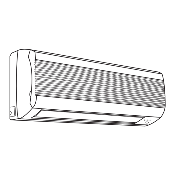
IDENTIFICATION OF THE PARTS INDOOR UNIT Air inlet AUTO STOP TEST Air outlet AUTO TEST STOP AUTO STOP Front panel Air filter Electrostatic filter (optional) Manual switch OUTDOOR UNIT Cable panel Activated carbon filter Louvers Air inlet Signal receiver LED display 10 Power plug 11 Drain hose 12 Remote control... - Page 6 OPERATION AND DISPLAY AUTO TEST STOP 1. Manual switch 4. Operation indicator This is used to start the appliance if the remote con- This comes on when the appliance is operating. trol is not working.* 5. Signal receiver 2. Heating indicator Receives the signals from the remote control.
-
Page 7: U I A
REMOTE CONTROL The remote control sends signals to the appliance. Liquid crystal display Displays all the operating modes. MODE button Used to select the operating mode. FAN button Used to set the fan speed, in sequence, to automatic, low, medium, high. SLEEP button Used to set or cancel SLEEP mode. - Page 8 HOW TO FIT THE BATTERIES • Remove the cover of the battery compartment in the direction of the arrow. • Fit the new batteries, making sure the (+) and (-) signs on the battery match correctly. • Put the cover back on by sliding it into position. Use 2 x R03 AAA (1.5 V) batteries.
-
Page 9: U I A
OPERATING MODES OPERATING MODES 1. Selecting the operating mode Each time that the MODE button is pressed the oper- ating mode is changed, in the following sequence: FULL AUTO COOLING FAN ONLY HEATING 2. FAN mode Each time that the FAN button is pressed, the speed is changed, in the following sequence: AUTO MEDIUM... -
Page 10: U I A
AUTO MODE AUTO OPERATING MODES Press the MODE button until displaying AUTO ( ); in this mode, the temperature and the fan speed are set auto- matically based on the actual room temperature. The operating mode and the temperature setting depend on the room temperature. -
Page 11: U I A
DRY MODE DEHUMIDIFICATION MODE Press the MODE button until displaying the DRY ( mode. The appliance will start according to the room tempera- ture and the set temperature: • If the room temperature is lower than the set tempera- ture, the compressor, the outdoor unit and the indoor unit will stop. -
Page 12: U I A
MAINTENANCE Unplug the appliance from the power outlet Replace the filters with the side marked as “FRONT” facing the outside Installation of the activated carbon filters* To remove the front panel, pull it outwards, as shown by the arrows in the figure - Remove the air filters - Remove the new filters from the packaging... -
Page 13: U I A
TROUBLESHOOTING FAULT POSSIBLE CAUSE Wait • Once switched off the air-conditioner cannot be started The appliance doesn't work for around 3 minutes • This smell may come from other sources, such as fur- Strange smell niture or the like. • This derives from the flow of refrigerant in the air-con- Sound of running water ditioner, and is not a fault. -
Page 14: Installation Instructions
INSTALLATION INSTRUCTIONS INSTALLATION DIAGRAM The distance from the ceiling must be greater than 150mm The distance from the The distance from wall must be greater the wall must be than 150mm greater than 150mm Flexible sleeve Insulation tape The clearance of the air outlet must be at The distance from the floor least 300mm... - Page 15 SELECTING THE BEST SITE Suitable places for installation of the indoor unit • Absence of obstacles near the air outlet so that the air can flow freely around the room. Indoor unit • Places where it is easy to make holes in the wall and lay the pipes.
-
Page 16: Installation Of The Indoor Unit
INSTALLATION OF THE INDOOR UNIT 1. INSTALLATION OF THE FASTENING PLATE Select the position for installing the fastening plate, according to of the location of the indoor unit and the layout of the pipes. Adjust the level of the fastening plate, using a straight- edge or a plumb line. - Page 17 Thermal insulation lining Power cable • Position the drain hose under the pipes. • Insulation material: polythene foam, thickness greater Drain hose Control cable than 6mm. Connection cables The drain hose must be supplied by the user. • The drain hose must run downwards, to assist drainage. •...
- Page 18 3. CONNECTING THE CABLE Indoor unit Front panel Terminal (inside) Connect the power cable to the indoor unit by connect- ing the wires to the terminals on the control panel indi- vidually, according to the connection to the outdoor unit. Console To make the connection to the indoor unit ter- Indoor unit...
- Page 19 CONNECTION DIAGRAM MODELS 7K - 9K -12K MODELS 17.3K-23.5K Indoor unit Outdoor unit Indoor unit Outdoor unit Terminal Terminal Terminal Terminal Yellow/Green Yellow/Green Yellow/Green Yellow/Green Brown Brown Brown Brown Power cable Power cable Blue Blue Blue Blue Check that the colours of the connections on the outdoor unit and the terminal block are not the same as those on the indoor unit.
-
Page 20: Installation Of The Outdoor Unit
INSTALLATION OF THE OUTDOOR UNIT 1. Install the drain fitting and the drain hose (heat pump model only) The condensate is drained from the outdoor unit when the appliance operates in heating mode. To avoid dis- turbing neighbours and to respect the environment, install a drain fitting and a drain hose to convey the condensate. -
Page 21: U I A Note
NOTES • Read this manual before installing and use the appliance. • The plug must remain accessible following the installation • Check that air does not enter the refrigerant system and of the appliance, so that the appliance can be unplugged if that there are no leaks of refrigerant when the air-condi- required.
Need help?
Do you have a question about the CPC206AU and is the answer not in the manual?
Questions and answers