Table of Contents
Advertisement
CONTENTS
I
I
I
I
A
I
A
I
A
A
I
A
I
A
COMPLIANCE
The company:
Range : CF-CP AR
Models : CP 20 ARE 290
CF-CP 30 ARE 290
CF-CP 40 ARE 290
• Low voltage Directive 73/23EEC,93/68 EEC,
• Electromagnetic compatibility Directive 89/336 EEC and 92/31EEC
The following symbols have been used in some parts of this booklet and inside the appliance:
U
User
I
Installer
A
After-sales service
20
20
21
21
22
22
22
23
23
U
26
U
28
U
28
DECLARATION OF COMPLIANCE
DeLonghi S.p.A.
Via L. Seitz, 47
31100 TREVISO ITALY
DECLARES
under its own responsibility that:
the AIR-CONDITIONERS
are in conformity with
Attention
Forbidden
Danger: live parts
I
A
I
A
I
A
I
A
I
I
Indoor unit installation
I
Outdoor unit installation
I
I
A
I
A
I
A
I
A
Danger: moving blades
Danger: high temperature
70°C
Fire hazard
U
29
29
30
30
31
31
32
34
35
35
36
U
I
A
Advertisement
Table of Contents

Subscribe to Our Youtube Channel
Related Manuals for DeLonghi CF-CP AR


Summary of Contents for DeLonghi CF-CP AR
-
Page 1: Table Of Contents
Via L. Seitz, 47 31100 TREVISO ITALY DECLARES under its own responsibility that: the AIR-CONDITIONERS Range : CF-CP AR Models : CP 20 ARE 290 CF-CP 30 ARE 290 CF-CP 40 ARE 290 are in conformity with • Low voltage Directive 73/23EEC,93/68 EEC, •... -
Page 2: General Recommendations
GENERAL RECOMMENDATIONS of the appliance will not be liable for any damage or After having removed the packing, check that the con- injury caused. tents are intact and complete. In the event of non-com- The unit should be installed in compliance with local pliance, contact the Agency which sold you installation and safety regulations. -
Page 3: Recommendations
RECOMMENDATIONS Extraordinary maintenance First aid measures Programmed maintenance always represents a saving in the running of the installation as well as preventing possible Inhalation faults. Remove the casualty from the area of exposure and To ensure trouble-free operation of the air-conditioner, it is keep him/her warm and still. -
Page 4: Size And Weight
SIZE AND WEIGHT INDOOR UNIT Model Weight OUTDOOR UNIT Model Weight RECEIVING THE PRODUCT The air-conditioner comes in two packs protected by card- board packaging and is accompanied by: It is advisable to remove the packing only when the air- conditioner has been located in the point of installation. -
Page 5: Quick Connector
QUICK CONNECTOR Components description A. Liquid line (high pressure) B. Vapor (low pressure) C. Cover D. Electrical CONNECTION OF THE UNIT BASIC OPERATION separation of split air condotioning system with minimal fluid The fast connector coupling uses a retractable sleeve and loss and air inclusion (see Figure 1). - Page 6 CONNECTION OF THE UNIT No tools are required to connect the coupling: a retractable pushed forward and locked into place, and shut when the sleeve and four latch pins hold the male and female halves handle is in the “full back” position (see figures 3-4). together.
- Page 7 CONNECTION OF THE UNIT TO DISCONNECT immediatly upon disconnection with the optional caps as - Shut off the air conditioning unit and unplug the unit from shows in Figures 6 & 7. the power outlet. - Don’t tamper with the valves while disconnected or allow - Wait five minutes for line pressures to equalize.
-
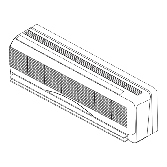
Page 8: Description Of The Air-Conditioner
DESCRIPTION OF THE AIR-CONDITIONER alternating current; it ensures high performance, efficiency air-conditioner is an appliance designed for and low noise operation. small user systems. It consists of an indoor unit for wall The speed may be changed according to needs. The heat mounting and an outdoor unit. - Page 9 DESCRIPTION OF THE AIR-CONDITIONER OUTDOOR UNIT The high efficiency sliding-vane compressor is on double vi- The large surface area exchange coil consists of scored bration-isolation flexible mountings and is activated by an copper pipes and aluminium fins. electric motor powered by alternating current and fitted with The air-conditioner is commanded and controlled by an an overload cutout.
-
Page 10: Technical Data
TECHNICAL DATA CP 20 CF 30 CP 30 CF 40 CP 40 ARE 290 ARE 290 ARE 290 ARE 290 ARE 290 Power supply V/f/Hz 230/1/50 Cooling capacity Btu/h 8013 12000 12000 17000 16320 2350 3520 3500 5000 4800 Kcal/h 2025 3035 3020... -
Page 11: Refrigerant Circuits
REFRIGERANT CIRCUITS Heating/Cooling Cooling HEATING COOLING Legend Cooler coil General filter Condenser coil Throttling part (capillary) Quick coupling Compressor Reversing Check valve valve INDOOR UNIT MULTIFILAR WIRING DIAGRAM LEGEND = Unit power card = Infrared receiver and leds card = EMC noise filter BLUE YELLOW 1 2 3 4 5 6... -
Page 12: Outdoor Unit Multifilar Wiring Diagram
OUTDOOR UNIT MULTIFILAR WIRING DIAGRAM (1) Cooling only model BLUE YELLOW/GREEN YELLOW/GREEN BROWN BROWN BLACK BROWN BLUE BLACK YELLOW/GREEN 6-way female connector (2) Heat pump model (front view) BLACK YELLOW/GREEN YELLOW/GREEN BROWN BROWN BLACK BLACK BROWN BLACK BLUE YELLOW/GREEN = Compressor power supply XS1 = Female connector FR1 = Overload cutout (compressor)) = Fan motor power supply... -
Page 13: Installation
INSTALLATION The place of installation should be established by the instal- The air-conditioner should be installed by a qualified com- lation designer or by a technically competent person and pany in accordance with relevant laws and regulations in should take into account technical requirements as well as force in the country of installation. -
Page 14: Installation Of The Outdoor Unit
INSTALLATION OF THE INDOOR UNIT - The hole in the wall should be made sloping downwards in Fig. 10 order to aid the natural flow of the condensate water, ob- serving the indications given in Fig.(11). - Having completed all the operations for installing the steel fixing plate, remove the reference cardboard template. - Page 15 INSTALLATION OF THE OUTOOR UNIT Installation of the outdoor unit drain line (if available) Fig. 14 During operation in the heating mode, the condensate water may be drained from the outdoor unit through three drain holes. Insert the drain male fitting into the hole where drainage of the condensate water is required and plug the remaining two holes using the plugs B supplied in the kit, as shown in Fig.(14).
-
Page 16: Condensate Drainage
CONDENSATE DRAINAGE The indoor unit is fitted with a condensate drain pipe, to Fig. 17 which a drainage hose (ø inside 16 mm) should be connec- Protection ted leading to a suitable drainage outlet. - Fasten the condensate drain pipe to the refrigerant pipes with adhesive tape whenever the lines cross through a wall;... -
Page 17: Routine Maintenance
ROUTINE MAINTENANCE Do not carry out any cleaning operations until you have disconnected the air conditioner from the power supply by setting the system’s main switch to “OFF”. CLEANING THE INDOOR UNIT The appliance should be cleaned using a slightly damp cloth. -
Page 18: User Diagnostics
USER DIAGNOSTICS If there is an alarm, keep the MODE key on the indoor unit indicating the nature of the problem connected with the keyboard pressed down for about 4 sec. and wait for the alarm. acoustic signal, which is followed by the blinking of the leds Room temp.
Need help?
Do you have a question about the CF-CP AR and is the answer not in the manual?
Questions and answers