
Related Manuals for HomeMatic HM-TC-IT-WM-W-EU


Summary of Contents for HomeMatic HM-TC-IT-WM-W-EU
- Page 1 Installation and operating manual (p. 43) Wireless Room Thermostat HM-TC-IT-WM-W-EU...
- Page 2 1st English edition 11/2013 Documentation © 2013 eQ-3 Ltd., Hong Kong All rights reserved. This manual may not be reproduced in any for- mat, either in whole or in part, nor may it be duplicated or edited by electronic, mechanical or chemical means, without the written con- sent of the publisher.
-
Page 3: Table Of Contents
Function ....... . . 49 General information about the HomeMatic system 49 General information about radio operation. -
Page 4: Information About This Manual
Information about this manual Information about this manual Read this manual carefully before beginning operation with your HomeMatic components. Keep the manual handy for later consultation! If you hand over the device to other persons for use, please hand over the operating manual as well. -
Page 5: Scope Of Supply
Any other use, e.g. on cooling systems, in-floor heating, etc., is not permitted and can lead to severe damages. Scope of supply 1 x HomeMatic Room Thermostat (HM-TC-IT-WM-W-EU) 2 x plugs 2 x adhesive strips 2 x screws 3.0 x 30 mm 2 x LR03/micro/AAA batteries... -
Page 6: Operation And Display
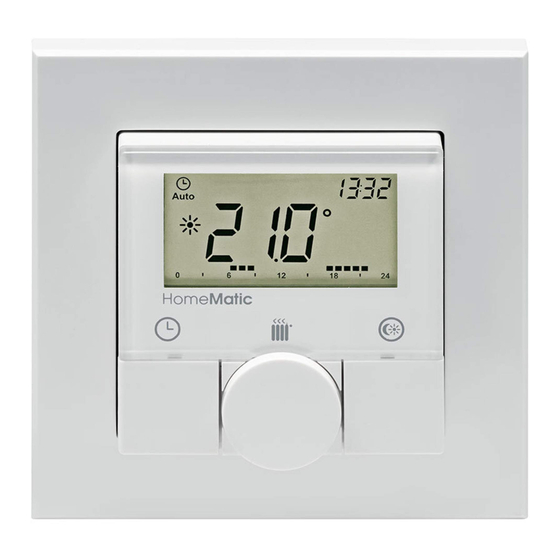
Operation and display Operation and display Display symbols and device buttons have the following meaning and functions: A Auto mode ( ) manu mode ( ), holiday mode ( date/time ( B Boost function ( C Comfort / eco temperature ( D Open window function ( Bar chart of programmed heating phases of current day Auto / manu button ( ): Switch between auto, manu... - Page 7 Operation and display Controls: (K) Mounting plate (L) Clip-on frame (M) Electronic unit...
-
Page 8: Function
General information about the HomeMatic system This device is part of the HomeMatic home control system and works with the bidirectional BidCoS® wireless proto- col. All devices are delivered in a standard configuration. The functionality of the device can also be configured with a programming device and software. The additional func-... -
Page 9: General Information About Radio Operation
Hereby, eQ-3 Entwicklung GmbH declares that this device conforms with the essential requirements and other rel- evant regulations of Directive 1999/5/EC. The full declaration of conformity is provided under www.homematic.com. Start-up Inserting (replacing) batteries To insert or replace the batteries, proceed as follows: • Once mounted, the electronic unit (M) can easily be... - Page 10 Start-up pull it out. You do not need to open the device. • Turn the electronic unit (M) over to remove or insert the batteries. • After removing the batteries you should wait approx. 10 seconds. • Insert 2 LR03 (micro/AAA) batteries in the battery com- partments (making sure that you insert them the right way round).
-
Page 11: Set Date And Time
Mounting You can either use screws or adhesive strips to mount the HomeMatic Room Thermostat to a wall. It can be mounted in the frame (L) supplied or be integrated into an existing switch (see sec. 8.4 for suitable switches). -
Page 12: Screw Mounting
Start-up are mounting the room thermostat must be clean, dry and free of grease. • For mounting of the assembled room thermostat, attach the adhesive strips to the back side of the mounting plate (K). You should be able to read the letters on the back side (according to figure). -
Page 13: Installation In Multiple Combinations
Start-up • Now drill the bore holes. If you are working with a stone wall, drill the marked two 5 mm holes and insert the plugs supplied. If you are working with a wooden wall, you can pre-drill 1.5 mm holes to make screws easier to insert. - Page 14 In both cases, mounting with adhesive strips and screws is possible. For mounting with multiple combinations, make sure that the mounting plate (K) of the room thermostat is seamlessly aligned to the already fixed mounting plate/retaining ring. The HomeMatic Room Thermostat is designed to fit into frames supplied by the following manufacturers: Manufac- Frame turer Berker S.1, B.1, B.3, B.7 glass...
- Page 15 Start-up Incorrect installation can put • your own life at risk; • and the lives of other users of the electrical system. Incorrect installation also means that you are running the risk of serious damage to property, e.g. because of a fire. You may be personally liable in the event of injuries or damage to property.
-
Page 16: Teach-In
Teaching-in to HomeMatic devices If you would like to teach-in the room thermostat to one or more HomeMatic devices, you must put the devices to be connected into teach-in mode and select the required teach-in channel. To do this, proceed as follows: During teach-in, please make sure you maintain a distance of at least 50 cm between the devices. - Page 17 ) is displayed, along with the teach-in time remaining in seconds. The teach-in time is 30 seconds. • Now put the device you wish to teach-in to the room thermostat (e.g. HomeMatic Radiator Thermostat, see the following fig.) into teach-in mode. Please follow the relevant operating manual instructions of the corre- sponding device.
- Page 18 • connected directly to other devices or • used in central control unit programs using a soft- ware-based method. For this purpose, it needs to be taught-in to the Home- Matic Central Control Unit first. New devices are taught-in to the central control unit using the HomeMatic “WebUI” user interface.
- Page 19 Each component can only be taught-in to one CCU. During teach-in, please make sure you maintain a distance of at least 50 cm between the HomeMatic devices and the central control unit. To teach-in your device to the central control unit, proceed as follows: • Open the “WebUI”...
- Page 20 • If required, you can teach-in additional devices by re- peating the steps described above for each device. • Now configure the newly taught-in devices in the inbox as described in the next section „Configuring newly taught-in devices:“. Configuring newly taught-in devices: Once you have taught-in your room thermostat to the HomeMatic Central Control Unit, it will be moved to the...
-
Page 21: Teach-Out/Restore Factory Settings
Please refer to the „WebUI“ manual for more details (you can find this in the „Downloads“ area of the website www.homematic.com). 10 Teach-out/Restore factory set- tings The factory settings of the room thermostat can be re- stored manually. -
Page 22: Operating Modes (Auto/Manu/Holiday)
21.0 °C and the eco temperature 17.0 °C. The comfort and eco temperature can be changed individually. If the room thermostat is used in connection with a HomeMatic Central Control Unit, settings can also be made via the user interface WebUI. • Press down the comfort/eco button ( ) for a few sec- onds (>... -
Page 23: Setting The Holiday Function
If the room thermostat is used in connection with a HomeMatic Central Control Unit, settings can also be made via the user interface WebUI. • Briefly press the auto/manu button (... -
Page 24: Boost Function
Boost function The set temperature will remain for the defined period of the holiday function. Otherwise, the room thermostat will change to auto mode. Radio control commands like those from a window contact or the weekly de-scaling run of a radiator thermostat will still be performed. 14 Boost function With the boost function, cool rooms can be heated within short at the touch of a button. -
Page 25: Configuration Menu
Configuration menu If the room thermostat is used in connection with a HomeMatic Central Control Unit, the duration of the Boost function and the valve opening can also be configured via the user interface WebUI. The radiant heat will not have an immediate effect if the radiator is covered or concealed (e.g. by a sofa). - Page 26 Configuration menu Menu items can be selected with the handwheel and con- firmed with the boost button ( ). By pressing the auto/ menu button ( ) again, you can return to the previous level. After successfully changing a menu item the display switches back to normal. The menu automatically closes without applying changes if there is no operation for more than 1 minute.
- Page 27 Configuration menu 15.1 Setting the week programme (Pro) In the week programme, for each weekday up to 6 heating phases (13 change settings) can be set separately. The programming is carried out for the days chosen, whereby temperature settings have to be set for the entire period between 00:00 and 23:59.
- Page 28 Configuration menu can change the start time with the handwheel. Confirm the setting with the boost button ( ). • Set the desired temperature with the handwheel for the next phase. Confirm the setting with the boost button ( ). • Repeat this procedure until temperatures are stored for the entire period between 0:00 and 23:59 h. Week programme: Example For each day of the week up to 6 heating phases (13 change settings) with individual temperature settings can be saved with the room thermostat.
- Page 29 Configuration menu The configured heating phases for one day are displayed by the bars. The displayed bars refer to the change set- tings. E.g. there are no bars displayed until the first change setting, this is followed by bars displayed until the second change setting, etc. 15.2 Changing date and time (dAt) In the configuration menu, date and time can be adjusted. • Press the auto/manu button ( ) longer than 3 seconds.
- Page 30 Configuration menu • Choose the menu item “SFA” with the handwheel. • Confirm the setting with the boost button ( ). If there are no error messages, “---” appears in the display. The error messages have the following meanings: communication error of taught-in radiator ther- mostat battery of taught-in window contact almost empty battery of taught-in remote control almost empty...
- Page 31 Configuration menu • Confirm your setting using the boost button ( ). • Set the option „On“ to activate automatic switching or set the option „OFF“ to deactivate automatic switching with the handwheel. • Confirm with the boost button ( ). 15.5 Setting offset temperature (tOF) As the temperature is measured on the room thermostat, the temperature distribution can vary throughout a room.
- Page 32 Configuration menu • Select “ACt” to display the actual temperature and “SEt” to display the setpoint temperature. • Confirm with the boost button ( ). 15.7 Change between actual temperature and humidity (t-H) In the configuration menu under “t-H” the automatic switch between the actual temperature and humidity can be acti- vated or deactivated. If the automatic switch is deactivated (“OFF”), only the actual temperature will be displayed.
-
Page 33: Child-Proof Lock/Operating Lock
Child-proof lock/operating lock • Use the handwheel to select the menu item “dEL” and confirm this with the boost button. • The display will show “no”. Select “YES” with the hand- wheel. Confirm with the boost button ( ) to delete all taught-in devices. The menu item “dEL” will only be displayed as long as the devices are not taught-in to the central control unit. -
Page 34: Additional Functions In Connection With Homematic Central Control Unit
Additional functions in connection with HomeMatic Central Control Unit on the display permanently. Operation of the device is now locked. • To deactivate the operating lock, press both buttons once again for at least 3 seconds. In connection with the HomeMatic Central Control... -
Page 35: Troubleshooting And Maintenance
(auto, manu, holiday or boost) can not be changed. The mode operating lock can only be activated/ deactivated via the WebUI (not on the device). You will find further information about operation and configuration of your HomeMatic Room Thermostat in connection with the WebUI user interface in the WebUI manual (available for download at www.homematic.com) - Page 36 Troubleshooting and maintenance Conflict during teaching-in: perform teach-out function there have already been 8 radiator thermostats taught-in; perform teach-out function Conflict during teaching-in: perform teach-out function there have already been 8 window sensors taught-in; Conflict during teaching-in, perform teach-out function no more connection partners possible Battery symbol Battery voltage low Replace batteries of room thermostat Battery symbol...
-
Page 37: Components That Can Be Taught-In
19 Components that can be taught- The following HomeMatic devices can be taught-in the the room thermostat: • max, 1 HomeMatic Central Control Unit (CCU or con- figuration adapter) • max. 8 HomeMatic Radiator Thermostats • max. 8 HomeMatic Door/Window Contact / Window Ro- tary Handle Sensors • max. -
Page 38: Technical Specifications
Technical specifications 20 Technical specifications Device short description: HM-TC-IT-WM-W-EU Supply voltage: 2 x 1.5 V LR03/micro/AAA Battery lifetime: approx. 1 year Current consumption: 40 mA (max.) Degree of protection: IP20 Protection class: Ambient temperature: 0 to 50 °C Dimensions (W x H x D) - Page 39 Technical specifications eQ-3 AG Maiburger Straße 29 D-26789 Leer www.eQ-3.de...
Need help?
Do you have a question about the HM-TC-IT-WM-W-EU and is the answer not in the manual?
Questions and answers