Table of Contents
Advertisement
Quick Links
EP-MVP4F
EP-MVP4F
EP-MVP4F
EP-MVP4F
EP-MVP4F
ISA
ISA
/PCI Mainboard with Onboard AGP
/PCI Mainboard with Onboard AGP
ISA
ISA /PCI Mainboard with Onboard AGP
ISA
/PCI Mainboard with Onboard AGP
/PCI Mainboard with Onboard AGP
VGA, PCI Audio, PCI IDE and Super
VGA, PCI Audio, PCI IDE and Super
VGA, PCI Audio, PCI IDE and Super
VGA, PCI Audio, PCI IDE and Super
VGA, PCI Audio, PCI IDE and Super
Multi-I/O
Multi-I/O
Multi-I/O
Multi-I/O
Multi-I/O
TRADEMARK
All products and company names are trademarks or
registered trademarks of their respective holders.
These specifications are subject to change without notice.
Manual Revision 1.0
August 9, 1999
Advertisement
Table of Contents

Subscribe to Our Youtube Channel
Related Manuals for EPOX EP-MVP4F


Summary of Contents for EPOX EP-MVP4F
- Page 1 EP-MVP4F EP-MVP4F EP-MVP4F EP-MVP4F EP-MVP4F /PCI Mainboard with Onboard AGP /PCI Mainboard with Onboard AGP ISA /PCI Mainboard with Onboard AGP /PCI Mainboard with Onboard AGP /PCI Mainboard with Onboard AGP VGA, PCI Audio, PCI IDE and Super VGA, PCI Audio, PCI IDE and Super...
-
Page 2: User Notice
EPoX has been advised of the possibility of such damages arising from any defect or error in the manual or product. EPoX may revise this manual from time to time without notice. - Page 3 EP-MVP4F serial number: _________________________________ Contacting Technical Support EPoX technical support is working hard to answer all of your questions online. From our website you can find answers to many common questions, drivers, BIOS updates, tech notes, and important technical bulletins. If you are still unable to locate the solution you are seeking, you always have the option to contact our support technicians directly.
-
Page 4: Table Of Contents
System Block Diagram ..........1-4 Section 2 Features EP-MVP4F Features ..........2-1 Section 3 Installation EP-MVP4F Detailed Layout ........3-1 Easy Installation Procedure Configure DIP Switch ..........3-3 System Memory Configuration ......... 3-5 Device Connectors ............. 3-7 Section 4 Award BIOS Setup BIOS Instructions ............ - Page 5 EP-MVP4F Save & Exit Setup ............4-26 Exit Without Saving ............ 4-26 Section 5 Appendix Appendix A Memory Map .............. A-1 I/O Map ............... A-1 Timer & DMA Channels Map ........A-2 Interrupt Map .............. A-2 RTC & CMOS RAM Map ........... A-3 Appendix B POST Codes ..............
- Page 6 EP-MVP4F Page Left Blank...
-
Page 7: Introduction
EP-MVP4F Introduction Section 1 INTRODUCTION Components Checklist ü ü ü ü ü (1) One mainboard ü ü ü ü ü (1) One user’s manual ü ü ü ü ü (1) Floppy ribbon cable ü ü ü ü ü (1) ATA-66 IDE ribbon cable ü... -
Page 8: Ep-Mvp4F Form-Factor
EP-MVP4F EP-MVP4F Form Factor The EP-MVP4F is designed with MicroATX form factor - the new industry standard of chassis. The MicroATX form factor is essentially a Baby-AT base- board rotated 90 degrees within the chassis enclosure and a new mounting configuration for the power supply. -
Page 9: I/O Shield Connector
EP-MVP4F Introduction I/O Shield Connector The EP-MVP4F is equipped with an I/O back panel.Please use the appropriate I/O shield (figure 3). parallel port Joystick/Midi PS/2 Mouse USB port PS/2 KEYBOARD COM1 VGA1 Speaker Line_in Figure 3 Power-On/Off (Remote) The EP-MVP4F has a single 20-pin connector for ATX power supplies. For ATX power supplies that support the Remote On/Off feature, this should be connected to the systems front panel for system Power On/Off button. -
Page 10: System Block Diagram
Introduction EP-MVP4F System Block Diagram socket 7 Processor 100/66 MHz PCI Bridge 100/66 MHz and memory controller VT82C501 A M R S lo t AC97 CODEC VT82C686A I/O Bridge USB 0 USB 1 Figure 5: System Block Diagram Page 1-4... -
Page 11: Features
Supports (2) 32 bit PCI slots, (1) AMR Slot and provides (2) independent high performance PCI IDE interfaces capable of supporting PIO Mode 3/4 and Ultra DMA 33/66 devices. The EP-MVP4F supports (2) PCI Bus Master slots and a jumperless PCI INT# control scheme which reduces configura- tion confusion when plugging in PCI card(s). - Page 12 Features EP-MVP4F • Supports ring-in feature (remote power-on through external modem, allows system to be turned on remotely). • Resume by Alarm - Allows your system to turn on at a preselected time. • Supports CPU Hardware sleep and SMM (System Management Mode).
- Page 13 EP-MVP4F Installation Page 3-1...
-
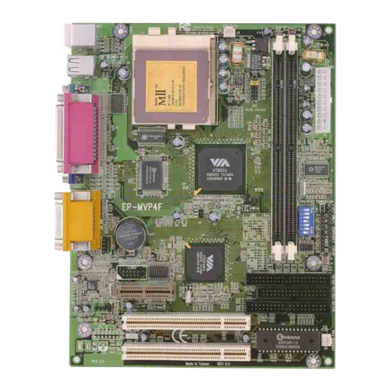
Page 14: Ep-Mvp4F Detailed Layout
Installation EP-MVP4F EP-MVP4F Detailed Layout Figure 1 Page 3-2... -
Page 15: System Memory Configuration
EP-MVP4F Installation The following must be completed before powering on your new system: 3-1. Configure Jumpers 3-2. System Memory Configuration 3-3. Device Connectors We design this motherboard with the fastest jumpers to make your install fast and easy. Note: The jumpers as depicted as shown (Figure 1) in their correct physical orientation. - Page 16 Installation EP-MVP4F CPU Type Multiplier Pentium/MMX Clock Cyrix /IBM AMD K6/K6-2/K6III IDT Winchip 2 Rise MP6 6x86MX/MII IDT-C6 166MHz PR200 ON ON 66MHz PR233 ON ON ON 75MHz PR266 233MHz ON ON 83MHz 2.5X PR300 *PR333 ON ON 95MHz 250MHz...
- Page 17 EP-MVP4F Installation The EP-MVP4F supports (2) 168-pin DIMMs (Dual In-line Memory Module). The DIMMs can be either EDO (Extended Data Out) or SDRAM (Synchronized DRAM). The DIMMs may be installed using just one chip. • DIMM SDRAM may be 83MHz (12ns), 100MHz (10ns) or 125MHz (8ns) bus speed.
- Page 18 Installation EP-MVP4F Figure 3 displays the notch marks and what they should look like on your DIMM memory module. DIMMs have 168-pins and two notches that will match with the onboard DIMM socket. DIMM modules are installed by placing the chip firmly into the socket at a 90 degree angle and pressing straight down (figure 4) until it fits tightly into the DIMM socket (figure 5).
- Page 19 EP-MVP4F Installation Please install the motherboard into the chassis. parallel port Joystick/Midi PS/2 Mouse USB port PS/2 KEYBOARD COM1 VGA1 Speaker Line_in Figure 6 Chassis Panel Connector • Power LED, Speaker, Reset Power_ON/OFF, Turbo LED, HDD LED, IR Connector CPU Fan Power •...
- Page 20 Installation EP-MVP4F (This is connected to the power button on the case. Using the Soft-Off by Pwr-BTTN feature, you can choose either Instant Off (turns system off immediatly), or 4 sec delay (you need to hold the button down for 4 seconds before the system turns off).
-
Page 21: Standard Cmos Setup
EP-MVP4F BIOS Award’s ROM BIOS provides a built-in Setup program which allows user to modify the basic system configuration and hardware parameters. The modified data will be stored in a battery-backed CMOS, so that data will be retained even when the power is turned off. In general, the information saved in the CMOS RAM will stay unchanged unless there is a configuration change in the system, such as hard drive replacement or a device is added. - Page 22 BIOS EP-MVP4F The menu displays all the major selection items. Select the item you need to reconfigure. The selection is made by moving the cursor (press any direction key ) to the item and pressing the ‘Enter’ key. An on-line help message is displayed at the bottom of the screen as the cursor is moved to various items which provides a better understanding of each function.
- Page 23 Selecting the “BIOS FEATURES SETUP” option in the CMOS SETUP UTILITY menu allows users to change system related parameters in the displayed menu. This menu shows all of the manufacturer’s default values for the EP-MVP4F. Pressing the [F1] key will display a help message for the selected item.
- Page 24 BIOS EP-MVP4F Virus Warning: During and after the system boots up, any attempt to write to the boot sector or partition table of the hard disk drive will halt the system and an error message will appear. You should then run an anti-virus program to locate the virus. Keep in mind that this feature protects only the boot sector, not the entire hard drive.
- Page 25 EP-MVP4F BIOS The following is your list of options: [A, C, SCSI] - [C, A, SCSI] - [C, CD-ROM, A] - [CD-ROM, C, A] [D, A,CD-ROM],[E, A, CD-ROM] - [F, A, CD-ROM] - [SCSI, A, C] [SCSI C, A] - [C Only] Swap Floppy Drive: This will swap your physical drive letters A &...
- Page 26 BIOS EP-MVP4F Typematic Rate (Chars/Sec): This is the number of characters that will be repeated by a keyboard press. The default is 6. 6: 6 characters per second. 8: 8 characters per second. 10: 10 characters per second. 12: 12 characters per second.
- Page 27 EP-MVP4F BIOS Video BIOS Shadow: This option allows video BIOS to be copied into RAM. Video Shadowing will increase the video performance of your system. The default is Enabled. Enabled: Video shadow is enabled. Disabled: Video shadow is disabled. C8000 - CBFFF Shadow:...
- Page 28 BIOS EP-MVP4F Choose the “CHIPSET FEATURES SETUP” in the CMOS SETUP UTILITY menu to display following menu. ROM PCI/ISA BIOS(2A5LHPA9) CHIPSET FEATURES SETUP AWARD SOFTWARE, INC. Bank 0/1 DRAM Timing : SDRAM Fast OnChip USB : Enabled Bank 2/3 DRAM Timing...
- Page 29 EP-MVP4F BIOS Sustained 3T Write: This item allow you to enable or disable direct map write back / write through secondary cache. The Choice: Enabled, Disabled. Cache R/CPU W Pipeline: This item allows you to enable/disabled the cache timing. The Choice: Enabled, Disabled.
- Page 30 BIOS EP-MVP4F 32: 32MB of systems memory accessable by the AGP card. 64: 64MB of systems memory accessable by the AGP card. 128: 128MB of systems memory accessable by the AGP card. 256: 256MB of systems memory accessable by the AGP card.
- Page 31 EP-MVP4F BIOS Choose the “POWER MANAGEMENT SETUP” in the CMOS SETUP UTILITY to display the following screen. This menu allows the user to modify the power management parameters and IRQ signals. In general, these parameters should not be changed unless it’s absolutely necessary.
- Page 32 10: IRQ 10 11: IRQ 11 The EP-MVP4F supports HDD Power Down, Doze and Standby power saving functions when using the Intel Pentium II Processor. The default is Disabled Doze Mode: The “Doze” mode timer starts to count when no “PM events” have occurred.
- Page 33 EP-MVP4F BIOS HDD Power Down: HDD Standby timer can be set from 1 to 15 minute(s). Soft-Off by PWR-BTTN: Use this to select your soft-off function. The default is Delay 4 sec. Instant Off: Turns off instantly. Delay 4 Second: Turns off after a 4 second delay. If momentary press of button, the system will go into Suspend Mode.
- Page 34 BIOS EP-MVP4F The PNP/PCI configuration program is for the user to modify the PCI/ISA IRQ signals when various PCI/ISA cards are inserted in the PCI or ISA slots. WARNING: Conflicting IRQ’s may cause the system to not find certain devices.
- Page 35 EP-MVP4F BIOS Reset Configuration Data: This setting allows you to clear ESCD data. The default is Disabled Disabled: Normal Setting. Enabled: If you have plugged in some Legacy cards to the system and they were recorded into ESCD (Extended System Configuration Data), you can set this field to Enabled in order to clear ESCD.
-
Page 36: Integrated Peripherals
BIOS EP-MVP4F The “LOAD SETUP DEFAULTS” function loads the system default data directly from ROM and initializes the associated hardware properly. This function will be necessary only when the system CMOS data is corrupted. ROM PCI/ISA BIOS(2A5LHPA9) INTEGRATED PERIPHERALS AWARD SOFTWARE, INC. - Page 37 EP-MVP4F BIOS IDE HDD Block Mode: IDE Block Mode allows the controller to access blocks of sectors rather than a single sector at a time. The default is Enabled. Enabled: Enabled IDE HDD Block Mode. Provides higher HDD transfer rates.
- Page 38 BIOS EP-MVP4F Primary Slave UDMA: This allows you to select the mode of operation for the hard drive. The default is Auto. Auto: The computer will select the optimal setting. Disabled: The hard drive will run in normal mode. Secondary Master UDMA: This allows you to select the mode of operation for the hard drive.
- Page 39 EP-MVP4F BIOS UART 2 Mode: This item allows you to determine which Infra Red (IR) function of onboard I/O chip. The Choice: Standard, ASKIR, HPSIR. Onboard Parallel port: This field allows the user to configure the LPT port. The default is 378H / IRQ7.
- Page 40 BIOS EP-MVP4F SB IRQ Select: Legacy audio device IRQ selection. SB DMA Select: Sound Blaster DMA channel selection. MPU-401: MPU-401 function enabled/disabled. MPU-401 I/O Address: Built-in MPU-401 compatible MIDI I/O port selection: 300-303H 310-313H 320-323H 330-333H (default) FM Port (388-38BH): Frequency modulation port at I/O port 388-38BH enabled/disabled.
-
Page 41: Sensor And Cpu Speed Setup
EP-MVP4F BIOS ROM PCI/ISA BIOS(2A5LHPA9) SENSOR AND CPU SPEED SETUP AWARD SOFTWARE, INC. Auto Detect DIMM/PCI Clk : Enabled Current CPU Temp. : 35 C/95 Spread Spectrum : Disabled Current System Temp. : 26 C/78 CPU Host Clock (CPU/PCI) : Default... - Page 42 BIOS EP-MVP4F CPUFAN Off In Suspend: This option is used to set if the CPU fans will turn off during suspend mode. The default is Enabled. Enabled: The system will turn off the CPU fans during suspend mode. Disabled: The system will not turn off the CPU fan during suspend mode.
- Page 43 EP-MVP4F BIOS To change the password, choose the “SUPERVISOR PASSWORD or USER PASSWORD” option from the CMOS SETUP UTILITY menu and press [Enter]. NOTE: Either “Setup” or “System” must be selected in the “Security Option” of the BIOS FEATURES SETUP menu.
-
Page 44: Ide Hdd Auto Detection
BIOS EP-MVP4F The “IDE HDD auto detection” utility is a very useful tool, especially when you do not know which kind of hard disk type you are using. You can use this utility to detect the correct disk type installed in the system automatically. But now you can set HARD DISK TYPE to Auto in the STANDARD CMOS SETUP. - Page 45 EP-MVP4F BIOS If user set his HDD to NORMAL mode, the maximum accessible HDD size will be 528 Megabytes even though its physical size may be greater than that! LBA (Logical Block Addressing) mode: A new HDD accessing method to overcome the 528 Megabyte bottleneck.
-
Page 46: Save & Exit Setup
BIOS EP-MVP4F Note: To support LBA or LARGE mode of HDDs, there must be some software involved. All the software is located in the Award HDD Service Routine (INT 13h). It may fail to access a HDD with LBA (LARGE) mode selected if you are running under an Operating System which replaces the whole INT 13h. -
Page 47: Appendix
EP-MVP4F Appendix Appendix A A-1 MEMORY MAP Address Range Size Description [00000-7FFFF] 512K Conventional memory [80000-9FBFF] 127K Extended Conventional memory [9FC00-9FFFF] Extended BIOS data area if PS/2 mouse is installed [A0000-C7FFF] 160K Available for Hi DOS memory [C8000-DFFFF] Available for Hi DOS memory and adapter... -
Page 48: Timer & Dma Channels Map
Appendix EP-MVP4F [2F8-2FF] SERIAL port 2. [360-36F] NETWORK ports. [378-37F] PARALLEL port 1. [3B0-3BF] MONOCHROME & PARALLEL port adapter. [3C0-3CF] EGA adapter. [3D0-3DF] CGA adapter. [3F0-3F7] FLOPPY DISK controller. [3F8-3FF] SERIAL port 1. A-3 TIMER & DMA CHANNELS MAP TIMER MAP: TIMER Channel 0 System timer interrupt. -
Page 49: Rtc & Cmos Ram Map
EP-MVP4F Appendix FLOPPY DISK (SMC CHIP). PARALLEL port 1. RTC clock. Available. Available. Available. PS/2 Mouse. MATH coprocessor. Onboard HARD DISK (IDE1) channel. Onboard HARD DISK (IDE1) channel. A-5 RTC & CMOS RAM MAP RTC & CMOS: Seconds. Second alarm. - Page 50 Appendix EP-MVP4F Base memory high byte. Extension memory low byte. Extension memory high byte. 19-2d 2E-2F Reserved for extension memory low byte. Reserved for extension memory high byte. DATE CENTURY byte. INFORMATION FLAG. 34-3F Reserve. 40-7F Reserved for CHIPSET SETTING DATA.
-
Page 51: Post Codes
EP-MVP4F Appendix Appendix B B-1 POST CODES ISA POST codes are typically output to I/O port address 80h. POST (hex) DESCRIPTION 01-02 Reserved. Turn off OEM specific cache, shadow. 1. Initialize EISA registers (EISA BIOS only). 2. Initialize all the standard devices with default values Standard devices includes. - Page 52 Appendix EP-MVP4F Create resource map from ESCD. 5. Assign IO & Memory for PCI devices. (PCI BIOS only) Initialization of the BIOS Data Area. (40:ON - 40:FF) 1. Program some of the Chipset's value according to Setup. (Early Setup Value Program) 2.
- Page 53 EP-MVP4F Appendix 2. Program all onboard super I/O chips (if any) including COM ports, LPT ports, FDD port ... according to setup value. 33-3B Reserved. Set flag to allow users to enter CMOS Setup Utility. 1. Initialize Keyboard. 2. Install PS2 mouse.
-
Page 54: Unexpected Errors
Appendix EP-MVP4F 5. Program parity according to Setup setting. 6. Power Management Initialization. Enable/Disable global PM. APM interface initialization. 1. If it is NOT a PnP BIOS, initialize serial & parallel ports. 2. Initialize time value in BIOS data area by translate the RTC time value into a timer tick value. -
Page 55: Appendix C Load Setup Defaults
EP-MVP4F Appendix Appendix C NOTE: The "LOAD SETUP DEFAULTS" function loads the system default data directly from ROM and initializes the associated hardware properly. This function will be necessary when you accept this mainboard, or the system CMOS data is corrupted. - Page 56 Appendix EP-MVP4F Page Left Blank A-10...
-
Page 57: Ghost 5.1 Quick User's Guide
EP-MVP4F Appendix Appendix D D-1 GHOST 5.1 Quick User’s Guide Installation is very easy. You only need to copy the Ghost5 folder or Ghost.exe to your hard disk. The current market version is for single Client, so the LPT and NetBios portions will not be explained further. - Page 58 Appendix EP-MVP4F There are 3 hard disk functions: 1. Disk To Disk (disk cloning) 2. Disk To Image (disk backup) 3. Disk From Image (restore backup) Important! 1. To use this function, the system must have at least 2 disks. Press the Tab key to move the cursor.
- Page 59 EP-MVP4F Appendix 4. Click OK to display the following confirmation screen. Select Yes to start. Disk To Image (Disk Backup) 1. Select the location of the Source drive. 2. Select the location for storing the backup file. A-13...
- Page 60 Appendix EP-MVP4F 3. Click OK to display the following confirmation screen. Select Yes to start. Disk From Image (Restore Backup) 1. Select the Restore file. 2. Select the Destination drive of the disk to be restored. A-14...
- Page 61 EP-MVP4F Appendix 3. When restoring disk backup, set the required partition size as shown in the following figure. 4. Click OK to display the following confirmation screen. Select Yes to start. Partition A-15...
- Page 62 Appendix EP-MVP4F There are 3 partition functions: 1. Partition To Partition (partition cloning) 2. Partition To Image (partition backup) 3. Partition From Image (restore partition) Partition To Partition (Partition Cloning) The basic unit for partition cloning is a partition. Refer to disk cloning for the operation method.
- Page 63 EP-MVP4F Appendix 3. Select the path and file name for storing the backup file. 4. Is the file compressed? There are 3 options: (1) No: do not compress data during backup (2) Fast: Small volume compression (3) High: high ratio compression. File can be compressed to its minimum, but this requires longer execution time.
- Page 64 Appendix EP-MVP4F Partition From Image (Restore Partition) Select the backup file to be restored. 2. Select the source partition. 3. Select the disk to be restored. A-18...
- Page 65 EP-MVP4F Appendix 4. Select the partition to be restored. 5. Select Yes to start restoring. Check This function checks the hard disk or backup file for backup or restoration error due to FAT or track error. A-19...
Need help?
Do you have a question about the EP-MVP4F and is the answer not in the manual?
Questions and answers