Table of Contents
Advertisement
Quick Links
1. The "LOAD SETUP DEFAULTS" function loads the system default data directly
from
ROM and initializes the associated hardware properly. This function is necessary
when you accept this mainboard, or the system CMOS data will corrupt.
STANDARD CMOS SETUP
BIOS FEATURES SETUP
CHIPSET FEATURES SETUP
POWER MANAGEMENT SETUP
PNP/PCI CONFIGURA
INTEGRATED PERIPH
LOAD SETUP DEFAULTS
ESC: QUIT
F10:Save & Exit Setup
Load Setup Defaults Except Standard COMS SETUP
2. KBPO(KeyBoard Power On) Function : There is a basic requirement that the
" +5V SB" power of the ATX power supply must be > = 0.1A (100mA).
Please refer to chapter 2-5 for detail.
Read me first
ROM PCI/ISA BIOS
CMOS SETUP UTILITY
AWARD SOFTWARE, INC.
SUPERVISOR PASSWORD
USER PASSWORD
IDE HDD AUTO DETECTION
HDD LOW LEVEL FORMAT
Load SETUP Default (Y/N)?
(Shift)F2 :Change Color
LOAD SETUP DEFAULT
ETUP
Y
SAVING
:SELECT ITEM
Advertisement
Table of Contents

Related Manuals for EPOX EP-MVP3G-M


Summary of Contents for EPOX EP-MVP3G-M
-
Page 1: Read Me First
Read me first 1. The "LOAD SETUP DEFAULTS" function loads the system default data directly from ROM and initializes the associated hardware properly. This function is necessary when you accept this mainboard, or the system CMOS data will corrupt. ROM PCI/ISA BIOS CMOS SETUP UTILITY AWARD SOFTWARE, INC. - Page 2 Apollo MVP3 AGPset MVP3G-M ISA/PCI/AGP MainBoard with Onboard PCI IDE and Super Multi-I/O. TRADEMARK All products and company names are trademarks or registered trademarks of their respective holders. The specification is subject to change without notice. V040...
-
Page 3: Components Checklist
One user’s manual ü ü ü ü ü Floppy ribbon cable ü ü ü ü ü IDE ribbon cables PS/2 to AT keyboard connector adapter (optional) ü ü ü ü ü Ultra_DMA IDE driver diskette AGP Drivers USERS MANUAL EP-MVP3G-M... -
Page 4: Table Of Contents
Contents page Chapter 1 - Introduction ........... Chapter 2 - Hardware Design ........... 2-1 Mainboard Layout ............2-2 Connectors and Jumpers ..........2-3 System Memory Configuration ........2-4 ATX Power ON/OFF Control ......... 2-5 External Modem Ring-in Power ON and Keyboard Power ON Functions .............. -
Page 5: Chapter 1 - Introduction
Introduction 1-1 Chapter 1 Introduction This mainboard is a high performance system hardware based on Intel Pentium processor and is equipped with an AGP slot, four PCI slots, three standard ISA slots, Super Multi-I/O controller and dual port PCI-IDE connectors for the future expansion. The hardware dimension is 305mm x 200mm with a four-layer-design technology. -
Page 6: Chapter 2 - Hardware Design
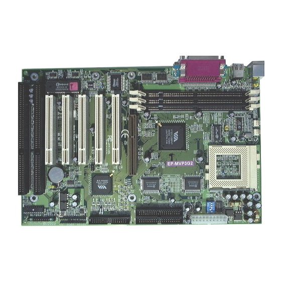
Hardware Design Chapter 2 Hardware design 2-1 Mainboard Layout This mainboard is designed with VIA Apollo MVP3 AGP/PCIset chipset which is developed by VIA Corporation to fully support Pentium Processor PCI/ISA system. By providing a massive increase in the bandwidth available between the video card and the processor (66MHz), the unique feature of AGP supported by VIA Apollo MVP3 chipset improves the speed of rendering and texturing for 3D graphics.The chipset also provides an integrated IDE controller with two high performance IDE... - Page 7 EP-MVP3G-M EP-MVP3G-M Layout Mouse PWR FAN CPU FAN PS/2 (Top) Keyboard SO C K E T 7 (Bottom) USB 1 (Top) USB 0 (Bottom) 6 12 3.2V 2.9V 2.8V 2.4V 2.2V 2.1V IDE2 IDE1 AGP SLOT Winbond PCI Slot #1...
-
Page 8: Connectors And Jumpers
Hardware Design 2-2 Connectors and Jumpers This section describes the connectors and jumpers equipped in the mainboard. Please refer to Figure 2-1 for the location of each connector and jumper. - Page 9 EP-MVP3G-M Please install the motherboard into the chassis. Now that your motherboard is installed you are ready to connect all your connections (figure 2-2). 1 2 3 4 5 6 7 8 9 0 1 2 3 4 5 6 7 8 9 0 1 2 3 4 5 6 7 8 9 0 1 2 1 2 3 4 5 6 7 8 9 0 1 2 3 4 5 6 7 8 9 0 1 2 3 4 5 6 7 8 9 0 1 2 1 2 3 4 5 6 7 8 9 0 1 2 3 4 5...
- Page 10 Hardware Design KeyLock - Keyboard lock switch & Power LED connector 1. Power LED(+) 4. Keylock 2. N/C 5. GND 3. GND Speaker - Connect to the system's speaker for beeping 1. Speaker 3. GND 2. N/C 4. GND Reset - Closed to restart system. IR Connector 1.
-
Page 11: System Memory Configuration
EP-MVP3G-M 2-3 System Memory Configuration This mainboard supports different type of settings for the system memory. The following figures and table provides all possible memory combinations. D IM M 1 B a n k 0 -S y B a n k 1... -
Page 12: Atx Power On/Off Control
Your system can be shut down automatically by an operation system such as Windows 95. POWER SUPPLY EP-MVP3G-M Board Case (chassis) Power ON/OFF momentary button (J3) Figure 2-2: Simple ATX Power ON/OFF Controller... -
Page 13: External Modem Ring-In Power On And Keyboard Power On Functions
Here, we would like to suggest you push 2 keys at the same time.. 2. Intel ATX version 2.0 specification has recommended you use the power supply with 0.72A(720mA). With our EP-MVP3G-M mainboard, the 5.0VSB standby power only has to be > = 0.1A (100mA) then you can enjoy this unique benefit. -
Page 14: Integrated Pci Bridge
Hardware Design 2-6 Integrated PCI Bridge This mainboard utilizes VIA Apollo MVP3 AGP/PCIset chipset to support Intel Pentium Processor PCI/ISA system. The VIA Apollo MVP3 PCIset chipset consists of the 82C598AT system controller (TSC), and one 82C596B PCI ISA/IDE Accelerator bridge chip. -
Page 15: Chapter 3 - Award Bios Setup
AWARD BIOS 3-1 CHAPTER 3 AWARD BIOS SETUP Award's ROM BIOS provides a built-in setup program which allows user to modify the basic system configurations and hardware parameters. The modified data will be stored in a battery-backed CMOS RAM so that data will be retained even when the power is turned off. -
Page 16: Standard Cmos Setup
CHAPTER 3 3-1 STANDARD CMOS SETUP Choose "STANDARD CMOS SETUP" in the CMOS SETUP UTILITY Menu (Fig.3-1). The STANDARD CMOS SETUP allows user to configure system setting such as the current date and time, type of hard disk installed, floppy type, and display type. Memory size is auto-detected by the BIOS and displayed for your reference. - Page 17 AWARD BIOS 3-3 ROM PCI/ISA BIOS(2A5LEPAD) BIOS FEATURES SETUP AWARD SOFTWARE, INC. Virus Warning : Disabled Video BIOS Shadow : Enabled CPU Internal Cache : Enabled C8000-CBFFF Shadow : Disabled External Cache : Enabled CC000-CFFFF Shadow : Disabled Quick Power On Self Test : Enabled D0000-D3FFF Shadow...
- Page 18 CHAPTER 3 Quick Power On Self Test:This category speeds up Power On Self Test (POST) after you power on the computer. If it is set to Enable, BIOS will shorten or skip some checking items during POST. Enabled : Enable quick POST. Disabled: Normal POST.
- Page 19 AWARD BIOS 3-5 Typematic Rate Setting This determines the typematic rate. Enabled Enable typematic rate and typematic delay programming. Disabled Disable typematic rate and typematic delay programming. The system BIOS will use default value of 2 items and the default is controlled by the keyboard.
-
Page 20: Chipset Features Setup
CHAPTER 3 C8000 - CBFFF Shadow : CC000 - CFFFF Shadow: D0000 - D3FFF Shadow: D4000 - D7FFF Shadow: D8000 - DBFFF Shadow: DC000 - DFFFF Shadow: These categories determine whether optional ROM will be copied to RAM by 16K byte or 32K byte per unit and the size depends on the chipset. - Page 21 AWARD BIOS 3-7 : The default value is Disabled. SDRAM Bank Interleave Disabled : Normal Setting. 2 Bank/4 Bank: SDRAM 2 or 4 Bank Interleave. Memory Hole at 15M-16M: The default value is Disabled. Disabled: Normal Setting. Enabled : This field enableds the main memory (15~16MB) remap to ISA BUS. : The default value is Disabled.
-
Page 22: Power Management Setup
CHAPTER 3 3-4 POWER MANAGEMENT SETUP Choose the "POWER MANAGEMENT SETUP" in the CMOS SETUP UTILITY to display the following screen. This menu allows the user to modify the power management parameters and IRQ signals. In general, these parameters should not be changed unless it is absolutely necessary. - Page 23 9: IRQ 9 10: IRQ 10 11: IRQ 11 The EP-MVP3G-M supports HDD Power Down, Doze and Standby power saving functions when using the Intel Pentium II Processor. The default is Disabled Doze Mode: The “Doze” mode timer starts to count when no “PM events” have occurred.
-
Page 24: Pnp/Pci Configuration
3-10 CHAPTER 3 Soft-Off by PWR-BTTN: Use this to select your soft-off function. The default is Delay 4 sec. Instant Off: Turns off instantly. Delay 4 Second : Turns off after a 4 second delay. If momentary press of button, the system will go into Suspend Mode. - Page 25 AWARD BIOS 3-11 PNP OS Installed: Do you have a PNP OS installed on your system. The default is No. Yes: Select if you are using a PNP OS No: Select if your OS does not support PNP. Resource Controlled By:The default value is Manual. Manual: The field defines that the PNP Card's resource is controlled by manual.
-
Page 26: Integrated Peripherals
3-12 CHAPTER 3 INTEGRATED PERIPHERALS ROM PCI/ISA BIOS(2A5LEPAD) INTEGRATED PERIPHERALS WARD SOFTWARE, INC. OnChip IDE Channel1 : Enabled Onboard Parallel Port : 378/IRQ7 OnChip IDE Second Channel1 : Enabled Onboard Parallel Mode : ECP / EPP IDE Prefetch Mode : Enabled ECP Mode Use DMA IDE HDD Block Mode : Enabled... - Page 27 AWARD BIOS 3-13 IDE Primary Master PIO: The default value is Auto. Auto : BIOS will automatically detect the Onboard Primary Master PCI IDE HDD Accessing mode. Mode0~4 : Manually set the IDE Accessing mode. IDE Primary Slave PIO: The default value is Auto. Auto : BIOS will automatically detect the Onboard Primary Slave PCI IDE HDD Accessing mode.
-
Page 28: Load Setup Defaults
3-14 CHAPTER 3 Onboard UART 2 Mode:The default value is standard. This field allows the User to select the COM2 port that can support a serial Infrared Interface. Standard: Support a Serial Infrared Interface IrDA. HPSIR: Support a HP Serial Infrared Interface format. ASKIR: Support a Sharp Serial Infrared Interface format. -
Page 29: Change Supervisor Or User Password
AWARD BIOS 3-15 ROM PCI/ISA BIOS(2A5LEPAD) CMOS SETUP UTILITY AWARD SOFTWARE, INC. STANDARD CMOS SETUP SUPERVISOR PASSWORD BIOS FEATURES SETUP USER PASSWORD CHIPSET FEATURES SETUP IDE HDD AUTO DETECTION POWER MANAGEMENT SETUP HDD LOW LEVEL FORMAT PNP/PCI CONFIGURA ETUP Load SETUP Default (Y/N)? INTEGRATED PERIPH SAVING LOAD SETUP DEFAULTS... -
Page 30: Ide Hdd Auto Detection
3-16 CHAPTER 3 3-9 IDE HDD AUTO DETECTION The "IDE HDD AUTO DETECTION" utility is a very useful tool especially when you do not know which kind of hard disk type you are using. You can use this utility to detect the correct disk type installed in the system automatically. - Page 31 AWARD BIOS 3-17 LBA (Logical Block Addressing) mode: This is a new HDD accessing method to overcome the 528 Megabyte bottleneck. The number of cylinders, heads and sectors shown in the setup may not be the number physically contained in the HDD. During the HDD accessing, the IDE controller will transform the logical address described by sector, head and cylinder into its own physical address inside the HDD.
-
Page 32: Hdd Low Level Format
3-18 CHAPTER 3 Note: To support LBA or LARGE mode of HDDs, there must be some softwares involved. All softwares are located in the Award HDD Service Routine (1NT 13h). It may fail to access a HDD with LBA (LARGE) mode selected if you are running under on Operating System which replaces the whole 1NT 13h. -
Page 33: I/O & Memory Map
TECHNICAL INFORMATION Chapter 4 Technical Information 4-1 I/O & MEMORY MAP MEMORY MAP Address Range Size Description [00000-7FFFF] 512K Conventional memory [80000-9FBFF] 127K Extended Conventional memory [9FC00-9FFFF] Extended BIOS data area if PS/2 mouse is installed [A0000-C7FFF] 160K Available for Hi DOS memory [C8000-DFFFF] Available for Hi DOS memory and adapter ROMs [E0000-EEFFF]... -
Page 34: Time & Dma Channels Map
CHAPTER 4 4-2 TIME & DMA CHANNELS MAP TIME MAP: TIMER Channel 0System timer interrupt. TIMER Channel 1DRAM REFRESH request. TIMER Channel 2SPEAKER tone generator. DMA CHANNELS : DMA Channel 0 Available. DMA Channel 1 Onboard ECP (Option). DMA Channel 2 FLOPPY DISK (SMC CHIP). -
Page 35: Rtc & Cmos Ram Map
TECHNICAL INFORMATION 4-4 RTC & CMOS RAM MAP RTC & CMOS : Seconds. Second alarm. Minutes. Minutes alarm. Hours. Hours alarm. Day of week. Day of month. Month. Year. Status register A. Status register B. Status register C. Status register D. Diagnostic status byte. -
Page 36: Appendix A: Post Codes
CHAPTER 4 APPENDIX A: POST CODES ISA POST codes are typically output to port address 80h. POST(hex) DESCRIPTION 01-02 Reserved. Turn off OEM specific cache, shadow. 1.Initialize EISA registers (EISA BIOS only). 2.Initialize all the standard devices with default values Standard devices includes. -DMA controller (8237). - Page 37 TECHNICAL INFORMATION POST(hex) DESCRIPTION Initialization of the BIOS Data Area. (40:ON - 40:FF) 1.Program some of the Chipset's value according to Setup. (Early Setup Value Program) 2.Measure CPU speed for display & decide the system clock speed. 3.Video initialization including Monochromc, CGA, EGA/VGA. If no display device found, the speaker will beep.
- Page 38 CHAPTER 4 POST(hex) DESCRIPTION 1.Display the Award Plug & Play BIOS Extension message. (PnP BIOS only) 2.Program all onboard super I/O chips (if any) including COM ports, LPT ports, FDD port ... according to setup value. 33-3B Reserved. Set flag to allow users to enter CMOS Setup Utility. 1.Initialize Keyboard.
- Page 39 TECHNICAL INFORMATION POST(hex) DESCRIPTION 1.Initialize all ISA ROMs. 2.Later PCI initializations. (PCI BIOS only) -assign IRQ to PCI devices. -initialize all PCI ROMs. 3.PnP Initialzations. (PnP BIOS only) -assign IO, Memory, IRQ & DMA to PnP ISA devices. -initialize all PnP ISA ROMs. 4.Program shadows RAM according to Setup settings.
-
Page 40: Appendix B: Connectors
CHAPTER 4 APPENDIX B: CONNECTORS ATX Power Supply Connector: Signal Name Signal Name 3.3V 3.3V -12.0V 3.3V PS-ON 5.0V 5.0V -5.0V PW-OK 5.0V 5VSB 5.0V 12.0V I/O back pannel connector: parallel port USB port PS/2 Mouse PS/2 Keyboard COM2 COM1... - Page 41 TECHNICAL INFORMATION PS/2 KEYBOARD & MOUSE CONNECTOR: Signal Name Data Clock COM1,COM2 : Serial Ports Connector Signal Name Signal Name SOUT LPT1 : Parallel Port Connector Signal Name Signal Name STROBE- AUTO FEED- Data Bit 0 ERROR- Data Bit 1 INIT- Data Bit 2 SLCT IN-...
- Page 42 4-10 CHAPTER 4 FDD1 : Floppy Disk Connector Signal Name Signal Name Ground FDHDIN Ground Reserved Ground FDEDIN Ground Index- Ground Motor Enable Ground Drive Select B- Ground Drive Select A- Ground Motor Enable Ground DIR- Ground STEP- Ground Write Data Ground Write Gate Ground...
-
Page 43: System Requirements
TECHNICAL INFORMATION 4-11 Appendix C : AGP Driver for Windows 95 Installation Guide This section provides the information for installation of Apollo VP3 VxD Driver which supports Accelerated Graphics Port (AGP) functionalities. SYSTEM REQUIREMENTS 1.Microsoft Windows 95 OSR2.1 (OSR2.0 with USB upgrade) 2.VIA Apollo VP3 AGP Driver (Vgart.VXD) 3.AGP VGA Card with Driver 4.Direct X5 DDk or SDK... - Page 44 4-12 CHAPTER 4 b. Click on "Direct X" then c. Click on "Direct Draw" and d. Check if there are some values existing in the "Bit" and "overlays." if there is, that means the AGP can be activated properly. REPLACING AN EXISTING VGA CARD WITH THE AGP VGA CARD 1.
Need help?
Do you have a question about the EP-MVP3G-M and is the answer not in the manual?
Questions and answers