
Related Manuals for Loctite 97152


Summary of Contents for Loctite 97152
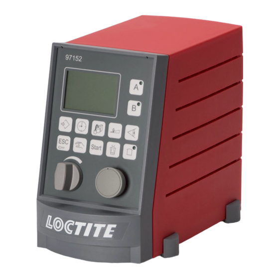
- Page 1 Operating Manual Bedienungsanleitung Universal-Steuergerät Dual Channel Controller 97152...
-
Page 3: Table Of Contents
Contents Please observe the following ..............52 Emphasized sections.......................52 Items supplied.........................52 Safety instructions ......................52 Field of application (Intended Use)................53 Description..................54 Theory of operation ......................54 Displays, operating elements and connections...............55 Start display - Overview....................62 2.1.1 Display overview......................62 2.1.2 Status numbers of program steps..................62 Controller access function ....................63 Modes of operation......................63 2.5.1... - Page 4 Contents Operation .................... 70 Lock/unlock controller ....................70 Programming procedure....................70 5.2.1 System setup........................70 5.2.2 Dispense channel configuration ..................71 5.2.3 Setup mode........................71 5.2.4 Timing setup........................71 5.2.5 Further adjustments......................71 5.2.6 Checking of setup......................71 Menu "System setup" ..................... 72 5.3.1 Language ........................
- Page 5 Contents 7.2.2 XS 2 Product reservoir ....................88 7.2.2.1 XS 2 product reservoir with digital level sensor (e.g. model 97125)......88 7.2.2.2 XS 2 Analog product reservoir (e. g. models 97106/97108)..........88 7.2.3 XS 3 Flow monitor ......................89 7.2.4 XS 5 Serial interface RS232...................89 7.2.5 XS 8 I/O Port ........................90 7.2.6...
-
Page 6: Please Observe The Following
As a result of technical development, the illustrations and descriptions in this operating manual may deviate in detail from the actual unit delivered. Safety instructions ® Please refer to the relevant Technical Data Sheet for the Loctite adhesive to be processed. Download from www.equipment-loctite.com or request the Technical Data Sheet and the Safety Data Sheet (acc. -
Page 7: Field Of Application (Intended Use)
Replace a damaged power cord immediately. Field of application (Intended Use) The Dual Channel Controller 97152 is a versatile multi-functional controller for actuating 1 – 2 dispensing valves as well as appropriate peripheral equipment such as reservoir, advancing slides, rotor sprays, on-line flow monitors, etc. -
Page 8: Description
Description Theory of operation ® Dual Channel Controller 97152 utilizes the latest microprocessor technology to The Loctite create a user-friendly control system for workstations in manufacturing environments. The controller is made up of a micro-controller core, a user interface keypad and graphic LCD display. -
Page 9: Displays, Operating Elements And Connections
Description Displays, operating elements and connections Display Displays all information required for setup, status, etc., see section 2.3 Precision pressure regulator Precision pressure regulator to regulate reservoir pressure. Turn the regulator knob to adjust the dispense pressure within a range from 0.00 bar to 700 bar (0 to 100 PSI). - Page 10 Description Key: Channel A Key: Channel B – To select the channel for further adjustments. – In the setup menus, these keys are used to switch the relevant options on or off. Key: Monitoring Without preselection of a channel, the online monitoring On/Off menu is displayed. With preselected channel, the online monitoring Setup menu is displayed.
- Page 11 Description Key: Preselection of stored dispense programs For manual selection of stored dispense applications. The display shows the selected application in the 3rd line, indicated as letters (a-d) in square brackets. Key: Time With preselected channel, the value setup menu is displayed. –...
- Page 12 Description 12 13 14 15 Key: Setup and Manual mode Without preselected channel, for the following settings: – Language setting, – Channel setting, – Factory settings, – Setup of dispense program change, and – Checking of input and output signals. With preselected channel, the adjustments for setup mode can be made, such as dispensing valve On or Off.
- Page 13 Description 16 17 18 19 20 Pneumatic Connection Reservoir Regulated air pressure supply (0 - 7 bar, 0 – 100 PSI) to the reservoir, for + 0.05 air hose OD Ø 6 mm , ID Ø 4 mm. –0.10 Pneumatic Connection A to a dispense valve 17, 18 I = Dispense valve open.
- Page 14 Description Connection XS 8 I/O Port Connection option for additional peripheral units. One input and one output for each channel, additionally two high-speed outputs, see section 7.2.5 "XS 8 I/O Port". Connection XS 5 RS232 Serial interface for connection of a programmable logic controller (PLC) or a PC for data readout or for firmware updating.
- Page 15 Description Connection XS 12 External solenoid valve module Use to connect the 15 pin connection cord to the optional external solenoid valve module 97204. Connection XS 1 Start Use to connect foot switch 97201. Two Start inputs each for channels A and B via special start splitter cable 97203. Connection XS 10 DC Drives Use to connect a DC motor with drive box.
-
Page 16: Start Display - Overview
Description Start display - Overview 2.3.1 Display overview This display is an overview of the most important parameters of all active channels. The factory default setting for Channel A is always in active mode. The display also shows the status of product supply if a reservoir has been connected. -
Page 17: Controller Access Function
Description Controller access function This function is a safety feature to safeguard the system against unauthorized manipulation. Enter a PIN as desired to prevent unauthorized users from configuring the controller, changing dispense applications, etc. Enter number "2000" to unlock. In locked condition, only the following functions can be accessed: –... -
Page 18: Menu Types
Description Menu types Push the relevant keys to open a menu. While the red ring on the Selector / Confirm button is illuminated, the button can be turned or pressed to – change settings such as dispense time, – scroll within a menu, but also to –... -
Page 19: Integrated Pneumatic Solenoid Valve Module: 1 Dispense Channel
The Flow Monitor is connected to connection XS 3, the product reservoir is connected to connection XS 2. Connectable components LOCTITE designations 1 dispense valve with double acting actuator – Diaphragm Valve 97135 or 97136 (for dispense valves with single acting –... -
Page 20: External Pneumatic/Electric Solenoid Valve Module: 2 Dispense Channels
The product reservoir is connected to connection XS 2. Dispense channels A/B, each Connectable components LOCTITE designations 1 dispense valve with double acting actuator – Diaphragm Valve 97135 or 97136 (for dispense valves with single acting –... -
Page 21: Factory Settings
Description Factory settings Factory settings for both dispense channels Advancing slide................Rotor.................... Flow monitor ................DC motor..................Continuous mode................. Common start ................Dispense time ................0.20 s Pre-delay time................Post-delay time ................Flow monitor ................Tolerance ..................Dispense measurement start point ..........Dispense measurement stop point .......... -
Page 22: Technical Data
Quality filtered 10 µm, oil-free, non-condensing If the required quality is not achieved, Order No. 88649 ® install a Loctite 97120 filter regulator. Adjustment range of the pressure 0.1 – 7.00 bar regulator Pressure indication 0.1 – 7.00 bar Pressure range of optional external 2.5 –... -
Page 23: Installation
– Avoid exposure to direct sunlight and UV radiation! – Avoid condensing humidity. – Avoid splash water. – For indoor use only. Not intended for use in potentially explosive areas. Space requirements 97152 Freiraum für Start Kabel und Schläuche Area to be left... -
Page 24: Operation
Operation Lock/unlock controller This function is a safety feature to safeguard the system against unauthorized manipulation, refer also to section 2.4. Lock • Keep ESC/Lock key 11 depressed for more than 3 s. • Turn the button to select a number which is not the number "2000". -
Page 25: Dispense Channel Configuration
Operation 5.2.2 Dispense channel configuration The key for Channel A is quoted only as an example. Push the key of the channel for which you have to make the adjustments. • First press key 4 Channel A, then key 7 Setup. –... -
Page 26: Menu "System Setup
Operation Menu "System setup" The first step is to preconfigure the controller. For this purpose, the controller must be unlocked. This menu is activated by pressing the key This is the menu for general setup of the dispensing system. Turn the button to select the desired entry which will be displayed in large letters, and confirm by pressing key 10 Enter. -
Page 27: Stored Dispense Program Changeover Types
Operation 5.3.4 Stored dispense program changeover types: This is the option for selecting the type of changeover for the stored dispense programs. – No changeover, as these programs will not be used. – Manual changeover by pressing key 8 Preselection of stored dispense programs –... -
Page 28: Menu "Dispense Channel Setup
Operation Menu "Dispense channel setup" This menu is activated by pressing the keys If the menu is activated without preselecting a channel, Channel A will be automatically switched to active mode. Setup options are the same for both channels. This is the menu where dispense channels A and B can be configured. -
Page 29: Menu "Setup Mode
Operation Menu "Setup mode" This menu is activated by pressing the keys Caution! In this mode, all units connected to the controller or to the external valve module will be actuated. For example, a connected advancing slide will move to its dispense position when the channel is switched on ( ). -
Page 30: Menu "Dispense, Pre-Delay And Post-Delay Times, Dc Motor Speed
Operation Menu "Dispense, pre-delay and post-delay times, DC motor speed" This menu is activated by pressing the keys This is the option for selecting – Dispense time, – Pre-delay time, – Postdelay time and – Percentage speed of a connected DC motor Use keys 4 Channel A or 5 Channel B to scroll through the menu. -
Page 31: Menu "Online Flow Monitor
Operation Menu "Online Flow Monitor" 5.7.1 Value setup This menu is activated by pressing the keys Pressing the key 6 Monitoring without preselecting a channel will automatically switch Channel A to active mode. Preselection of the dispense channel is required to call up the setup menu for Channel B. -
Page 32: Setup Of Reservoir Pressure, Empty And Refill Signals
Operation Setup of reservoir pressure, empty and refill signals 5.8.1 Reservoir pressure setup • Turn the regulator knob 2 to adjust the dispense pressure within a range from 0.00 bar to 7.00 bar (0 to 100 PSI). If error message “12 Supply?“ is displayed with a beep, the dispense pressure setting was changed by more than ±... -
Page 33: Setup Of Dispense Time
Operation 5.10 Setup of dispense time This menu is activated by pressing the keys • Turn the button to select the desired dispense time and press key 10 Enter to store. This section explains the necessary steps for adjusting the required amount of product to be dispensed. - Page 34 Operation Outgassing of products To avoid problems due to outgassing of products, use low dispense pressure and longer dispense timing for your process whenever possible. In addition, it is helpful to depressurize the dispense valve at regular intervals. If possible, reduce the valve closing speed (refer to operating manual of relevant dispense valve). High viscosity products Use a feed line with larger internal diameter for dispensing high viscosity products.
-
Page 35: Programming Of Online Flow Monitor
Operation 5.11 Programming of Online Flow Monitor The integrated flow monitoring function of controller 97152 is used for monitoring the quality of adhesive applied to the parts. This means that the flow monitor detects and evaluates the following dispensing malfunctions: –... -
Page 36: Actuate Flow Monitoring
Operation 5.11.1 Actuate flow monitoring • Push the key for the channel for which the monitoring function is to be activated. Screens displayed are different for each operating mode. Screen display in time-controlled mode Measurement curve Boundary line Boundary line Measurement Measurement End of Evaluation... -
Page 37: Setup Of Parameters For Monitoring
Operation 5.11.2 Setup of parameters for monitoring • Push the key for the channel for which the monitoring function has been activated. • Push key 6 Monitoring to go to the setup menu. If no graph is indicated, this means that no dispense monitoring function has been activated for this channel. -
Page 38: Setup Of Reference Dispensing
Operation Setup of measuring time factor • Press key 4 Channel A, or key 5 Channel B. Adjustable factor: 1-10. • For adjustments of values see section 5.1. • Press key 10 Enter to store the settings and return to the Monitoring screen 5.11.3 Setup of reference dispensing •... - Page 39 Operation Monitoring status screen This overview shows the current status of connected flow monitors. • Without channel preselection, press key 6 Monitoring twice. Status displayed in time controlled dispense mode: I:00000 +00000 -00000 D:00000 +00000 -00000 P:0000 +0000 -0000 T:00000 +00000 -00000 Status displayed in continuous dispense mode:...
-
Page 40: Troubleshooting
Troubleshooting Malfunction Possible Cause Corrective Action • Check supply voltage. Digital display does not light – No power supply. • Set power switch 22 to position I – Power switch 22 in position O (Off). (On). – Power fuse 31 defective. •... -
Page 41: Annex
Annex Spare parts and accessories Item no. Description Type no. Order no. – I/O Multiplex Box XS 8............97522 840911 – I/O Multiplex Box XS 12............97521 840910 – Splitter cable XS 3/XS 4 ............97529 945063 – Start splitter cable..............97203 142638 –... -
Page 42: Xs 2 Product Reservoir
Annex 7.2.2 XS 2 Product reservoir 7.2.2.1 XS 2 product reservoir with digital level sensor (e.g. model 97125) Reservoir Controller digital Levelsensor blue Tank Refill 0VDC/GND Tank Empty black brown + 24V 0VDC 0VDC Identification Signal + 24V + 24V Output 7.2.2.2 XS 2 Analog product reservoir (e. -
Page 43: Xs 3 Flow Monitor
Annex 7.2.3 XS 3 Flow monitor Controller Pre-Amplifier Analogue/IN Sensor Signal A 0-10VDC Analogue/IN Sensor Signal B 0-10VDC Identification Signal + 24VDC All other pins may never be connected! 7.2.4 XS 5 Serial interface RS232 To be connected via serial cable, pins 7 and 8 must not be assigned. Observe the serial interface protocol. -
Page 44: Xs 8 I/O Port
Annex 7.2.5 XS 8 I/O Port Controller I/O Output A I/O Output B Hi-Speed Output A Hi-Speed Output B I/O Inputg A I/O Input B GND Output GND Input +24 VDC 7.2.6 XS 10 PLC 7.2.6.1 XS 10 PLC internal power supply Controller Ready Channel A Ready Channel B... -
Page 45: Xs 10 Plc External Power Supply
XS 11 DC drive Controller DC Drive Tx 2 RS232 Interface Rx 2 + 24 VDC Drive enable Speed A out (0-10V) Speed B out (0-10V) Tacho A Caution! TTL Signals! 5V! Interface only for the use with LOCTITE drives! -
Page 46: Xs 12 External Solenoid Valve Module
Annex 7.2.8 XS 12 External solenoid valve module Controller Solenoid Modul Start Rotor C Dispensing Valve C Dispense Valve C Adv. Slide C in front Analogue/IN Analogue/IN Adv. Slide C in front Analogue/IN Advancing Slide C Adv. Slide C back +0VDC Dispensing Valve D Start Rotor D... -
Page 47: Ec Declaration Of Conformity
European regulations, harmonized standards, national standards and technical specifications listed below. Designation of the unit Dual Channel Controller 97152 Equipment item no. 1275665... - Page 48 Henkel AG & Co. KGaA Standort München Gutenbergstraße 3 D-85748 Garching b. München Henkel AG & Co. KGaA 2009...
Need help?
Do you have a question about the 97152 and is the answer not in the manual?
Questions and answers