Table of Contents

Related Manuals for AZZA DVAX2+


Summary of Contents for AZZA DVAX2+
- Page 1 DVAX2+ 6VAX2+ Pentium II/III Celeron Twin Processor VIA 693A ATX MAINBOARD ( VER. 1.x ) USER’S MANUAL DOC. NO. UM-DVAX2+-E2 …………………………………………………..……………..……..…………. PRINTED IN TAIWAN...
-
Page 2: Table Of Contents
TABLE OF CONTENTS VIA 693A ATX MAINBOARD TABLE OF CONTENTS CHAPTER & SECTION PAGE 1. INTRODUCTION OVERVIEW ..................1-1 MAINBOARD LAYOUT ..............1-2 SPECIFICATIONS ................1-3 2. INSTALLATION UNPACKING ..................2-1 AMAZING WAYS TO POWER ON THE PC SYSTEM....2-2 POWER OFF THE PC SYSTEM............2-3 3. - Page 3 VIA 693A ATX MAINBOARD SOMETHING IMPORTANT ! ¶ TRADEMARKS All trademarks used in this manual are the property of their respective owners. ¶ LOAD SETUP DEFAULTS “LOAD SETUP DEFAULTS” is the function which will have the BIOS default settings loaded into the CMOS memory, these default settings are the best-case values which will optimize system performance and increase system stability This function will be necessitated when you receive this mainboard, or when the system CMOS data is corrupted.
-
Page 4: Introduction
INTRODUCTION VIA 693A ATX MAINBOARD 1. INTRODUCTION OVERVIEW This Mainboard is a high performance personal computer mainboard. It is the ATX form-factor mainboard with both Slot 1 and Socket 370 on the board for various purposes. The VIA 693A and Winbond® I/O chipset are chosen as the core logic of the mainboard to support 66MHz, 100MHz and 133MHz FSB clock. -
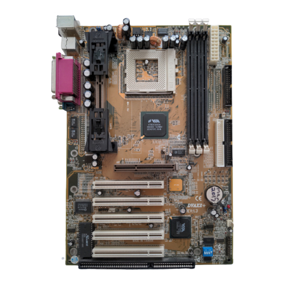
Page 5: Mainboard Layout
INTRODUCTION VIA 693A ATX MAINBOARD MAINBOARD LAYOUT CN5 Parallel Port PS/2 Mouse CN12 USB 1 JP133 JP100 PS/2 K/B IR Port USB 2 CN4 CN3 KB/Mouse. Power On Sel. CN13 CN16 CPU Fan Socket 370 PW ( Power SW SL ( Sleep LED JP12 JP11... -
Page 6: Specifications
INTRODUCTION VIA 693A ATX MAINBOARD SPECIFICATIONS ¥ CPU Intel® Pentium™ II, Pentium™ III or Celeron™ (for Slot and Socket type ) 233, 266, 300, 333. 350, 366, 400, 433, 450, 466, 500MHz and higher speed processors (6VAX2+ supports only the socket 370 CPU) ¥... - Page 7 INTRODUCTION VIA 693A ATX MAINBOARD ¥ SUPER I/O PORTS 1. Two high speed NS16C550 compatible serial ports (UARTs). 2. One parallel port, supports SPP/EPP/ECP mode. 3. One Floppy Disk Control port. ¥ IR PORT One HPSIR and ASKIR compatible IR transmission connector (5-pin). One Consumer IR transmission connector (4-pin, optional).
-
Page 8: Installation
INSTALLATION VIA 693A ATX MAINBOARD 2. INSTALLATION UNPACKING The mainboard contains the following components. Please inspect the following contents and confirm that everything is there in the package. If anything is missing or damaged, call your supplier for instructions before proceeding. l This mainboard. -
Page 9: Amazing Ways To Power On The Pc System
INSTALLATION VIA 693A ATX MAINBOARD 2.2 AMAZING WAYS TO POWER ON THE PC SYSTEM When the mainboard has been installed successfully, there are several ways to power on the system. Please read the following description for all the details. ¨ POWER BUTTON The power button can be programmed by COMS setup program and it has different features. -
Page 10: Power Off The Pc System
INSTALLATION VIA 693A ATX MAINBOARD ¨ RTC ALARM PC system can be waked up by the RTC setting in the CMOS. You can set the alarming date and time in the BIOS setup program, When RTC alarms, the PC system will be triggered and wakes up automatically. Enable the “RTC Alarm Resume”... -
Page 11: Hardware Setup
HARDWARE SETUP VIA 693A ATX MAINBOARD 3. HARDWARE SETUP Before you can start to install this mainboard, some hardware settings is required to make sure it will work perfectly with the devices which you are going to install in your PC system. To configure the mainboard is a simple task, only a few jumpers, connectors, cables and sockets needs to be selected and configured. -
Page 12: Installing The Dram Modules
HARDWARE SETUP VIA 693A ATX MAINBOARD When you have installed the processor onto the mainboard, it will detect the CPU type and decide the CPU voltage automatically. So you don’t have to make any jumper setting to select the CPU voltage. 3.2 INSTALLING THE DRAM MODULES This mainboard has three DIMM sockets designed on the mainboard, all the DIMM sockets on the mainboard support the single side and double side DIMM... -
Page 13: Connectors
HARDWARE SETUP VIA 693A ATX MAINBOARD ( Double-Side DIMM Module ) 2. Minimum one DIMM module must be installed on the mainboard. 3. You can use single side or double side DIMM module on this mainboard. 4. Always install DIMM module starting from DIMM 1 socket first, and then DIMM 2 and DIMM 3. - Page 14 HARDWARE SETUP VIA 693A ATX MAINBOARD (B) CN1CN2: PS/2 Mouse and Keyboard Connector CN2 : PS/2 Mouse Connector CN1 : PS/2 Keyboard Connector (C) CN3 : Serial Port COM 1 Connector (D) CN4 : Serial Port COM 2 Connector COM 1 COM 2 ( COM ports viewed from the real panel) Ping assignment of serial port connector:...
- Page 15 HARDWARE SETUP VIA 693A ATX MAINBOARD (E) CN5: Parallel Port Connector The parallel port on the mainboard supports SPP/EPP/ECP modes, IRQ7 or IRQ5 is selectable, ECP mode will use either DMA channel 3 or channel 1 which can be selected by the CMOS setup program Parallel Port Pin assignment of parallel port: 1 14...
- Page 16 HARDWARE SETUP VIA 693A ATX MAINBOARD (F) CN6: USB Port 1 (Universal Serial Bus) Connector (G) CN7: USB Port 2 (Universal Serial Bus) Connector CN6 USB 1 CN7 USB 2 Pin assignment of USB connector: Pin1: +5VDC USB 1 USB 2 Pin2: DATA- Pin3: DATA+ Pin4: Ground...
- Page 17 HARDWARE SETUP VIA 693A ATX MAINBOARD (I) CN9 : IDE 1 Connectors (Primary ATA/66 IDE Port: 1F0H, IRQ 14) (J) CN10: IDE 2 Connectors (Secondary ATA/66 IDE Port: 170H, IRQ 15) These two IDE ports are the standard IDE interface on the mainboard and they are ATA/66 and backward compatible.
- Page 18 HARDWARE SETUP VIA 693A ATX MAINBOARD (L) CN13: CPU Cooling Fan Power Connector +12V CN13 Fan Signal (M) CN15: ATX Power Connector CN15 ATX Power connector...
- Page 19 HARDWARE SETUP VIA 693A ATX MAINBOARD (N) CN16: WOL (Wake On LAN) Connector In order to use the WOL LAN card to trigger the power of the PC system, the switching power supply must be able to provide at least 700mA current driving ability on the “5V standby”...
- Page 20 HARDWARE SETUP VIA 693A ATX MAINBOARD (R) Push buttons and LED connectors A series of connectors are designed on the mainboard to connect the push buttons and LED indicators on the front panel. Followings are the details: RS: Reset Button connector HL: HDD LED connector SL: Sleep LED connector PW: Power On / Off Suspend switch...
- Page 21 HARDWARE SETUP VIA 693A ATX MAINBOARD IDE HDD LED Connector Pin # Signal name + 5V DC Pull-up HDD Active Signal Sleep LED Connector This LED will be lightened when the AC power is connected and the system is power off, darkened when the AC power is disconnected or the system is powered on.
- Page 22 HARDWARE SETUP VIA 693A ATX MAINBOARD unable to use the PW button to power on the PC system, please see Section 2.2 and Section 4.9 for more details. ) B. When system power is on : Click on this switch, the system will be powered off instantly. (S) Speaker and Key Lock connector: 1 2 3 4 5 1 2 3 4 5...
-
Page 23: Jumpers
HARDWARE SETUP VIA 693A ATX MAINBOARD 3.4 JUMPERS This section will discuss the jumper setting on the mainboard. In order to let you have better idea of the jumper setting, please see below for the explanation of jumper settings before you start this section. open short The following jumpers which labeled with “optional”... - Page 24 HARDWARE SETUP VIA 693A ATX MAINBOARD BIOS DIMM1 DIMM2 DIMM3 1-2 Short 2-3 Short Normal Setting Clear CMOS Note: JP9 is designed to clear the information which is stored in the CMOS memory. Improper connection on JP9 will cause mainboard failed to work.
- Page 25 HARDWARE SETUP VIA 693A ATX MAINBOARD JP12 is a special design on the mainboard which allows you to select the CPU voltage range (Vcore) to protect the processor from damage by accident. The voltage regulator on the mainboard will generate 1.3V ~ 3.5V DC to support different processors.
- Page 26 HARDWARE SETUP VIA 693A ATX MAINBOARD (E) JP100 & JP133: FSB Clock Selection JP100 and JP133 are designed on the board to select the Front Side Bus (FSB) clock speed for some special purpose. (Please do not attempt to change this setting unless you are the technician).
- Page 27 HARDWARE SETUP VIA 693A ATX MAINBOARD (F) SWITCH SETTINGS There is one "toggle switch" designed on the mainboard to select the CPU clock ratio. Basically, you have to check the specification of your CPU carefully because some of the CPU does not allow you to change its default clock ratio setting. In another word.
-
Page 28: Installation Of Device Drivers
HARDWARE SETUP VIA 693A ATX MAINBOARD 3.5 INSTALLATION OF DEVICE DRIVERS There is a CD which comes with the mainboard. The CD contains the device drivers which is necessary when installing the mainboard. Please refer to the following procedures to install the device drivers. A. -
Page 29: Award Bios Setup
AWARD BIOS SETUP VIA 693A ATX MAINBOARD AWARD BIOS SETUP 4.1 GETTING STARTED When the system is first time powered on or reset by user, the system BIOS will enter the POST routines (Power On Self Test), which will execute a diagnostics and initialize the computer. -
Page 30: Control Keys
AWARD BIOS SETUP VIA 693A ATX MAINBOARD 4.3 CONTROL KEYS Listed below is the explanation of the keys displayed at the bottom of the screens which will be used in the CMOS SETUP program : Arrow Keys : Use the arrow keys to move the cursor to the desired item. Enter : Select the desired item. -
Page 31: Bios Features Setup
AWARD BIOS SETUP VIA 693A ATX MAINBOARD MODE : The BIOS on the mainboard is the updated one and which provides three different modes to support both normal IDE HDD and the one which is above 528MB: Ø NORMAL : For IDE hard disk drives which is smaller than 528MB. Ø... - Page 32 AWARD BIOS SETUP VIA 693A ATX MAINBOARD Virus Warning : Basically, The default setting of this feature is "Disabled". In order to avoid virus intruding happens on your PC system, This mainboard provides the virus warning features in the BIOS. During and after the operation system is loaded, any attempt to write to the boot sector or partition table on the IDE hard disk drive will trigger this feature and give you some warning messages on the screen and then halt the system.
- Page 33 AWARD BIOS SETUP VIA 693A ATX MAINBOARD Security Option : ( default setting: Setup ) This selection field allows you to select how to secure the PC system for you. There are two choice selectable - "Setup" and "System". Before you can apply the security option to your PC system, you have to select your own ""Supervisor Password"...
-
Page 34: Chipset Features Setup
AWARD BIOS SETUP VIA 693A ATX MAINBOARD 4.6 CHIPSET FEATURES SETUP ROM PCI / ISA BIOS (2A69LGXXX) CHIPSET FEATURES SETUP AWARD SOFTWARE, INC. Bank 0/1 DRAM Timing :SDRAM 8/10ns Auto Detect DIMM/PCI Clk : Enabled Bank 2/3 DRAM Timing :SDRAM 8/10ns Spread Spectrum : Disabled Bank 4/5 DRAM Timing... - Page 35 AWARD BIOS SETUP VIA 693A ATX MAINBOARD Memory Hole In order to improve performance, certain space in memory is reserved for ISA cards. This memory must be mapped into the memory space below 16MB. This field allows you to decide the memory mapping. Read Around Write : ( default setting : “Disabled”...
- Page 36 AWARD BIOS SETUP VIA 693A ATX MAINBOARD USB Keyboard Support: ( Default setting: “Disabled” ) If you are going to use the USB keyboard in the PC system..please Enable the selection field, otherwise, leave it “Disabled” Auto Detect DIMM/PCI Clk: ( default setting : “Enable” ) When “Enabled”...
-
Page 37: Power Management Setup
AWARD BIOS SETUP VIA 693A ATX MAINBOARD 4.7 POWER MANAGEMENT SETUP ROM PCI / ISA BIOS (2A6LGXXX) POWER MANAGEMENT SETUP AWARD SOFTWARE, INC. ACPI function Disabled Primary INTR : ON Power Management :User Define IRQ3 (COM 2) : Primary PM Control by APM : Yes IRQ4 (COM 1) : Primary... - Page 38 AWARD BIOS SETUP VIA 693A ATX MAINBOARD There are three selections for Power Management, please refer to the following for the feature description. Disable (default) No power management. Disables all four modes Min. Power Saving Minimum power management. Doze Mode = 1 hr. Standby Mode = 1 hr., Suspend Mode = 1 hr., and HDD Power Down = 15 min.
- Page 39 AWARD BIOS SETUP VIA 693A ATX MAINBOARD Modem Use IRQ: (Default setting: 3 ) This mainboard has the ACPI feature designed on the board and it will “wakeup” automatically when it detects the incoming modem Ring-in signal. Before you can use the Ring-in signal to wakeup your PC system, you have to install the “External”...
- Page 40 AWARD BIOS SETUP VIA 693A ATX MAINBOARD DMA/master: ( Default setting: “OFF”.) When set to On (default), any event occurring at will awaken a system which has been powered down. Modem Ring Resume: ( Default setting: “Disabled”.) When set to Enabled , any event occurring to the Modem Ring will awaken a system which has been powered down.
-
Page 41: Pnp/Pci Configuration
AWARD BIOS SETUP VIA 693A ATX MAINBOARD PNP/PCI CONFIGURATION ROM PCI / ISA BIOS (2A6LGXXX) PNP/PCI CONFIGURATION AWARD SOFTWARE, INC. PNP OS Installed CPU to PCI Write Buffer : Enabled Resources Controlled By : Manual PCI Dynamic Bursting : Enabled Reset Configuration Data : Disabled PCI Master 0 WS Write... - Page 42 AWARD BIOS SETUP VIA 693A ATX MAINBOARD Reset Configuration Data : Disabled : The system BIOS will do nothing. Enabled : The system BIOS will clear (reset) the ESCD data during “POST”. After clearing the ESCD data, the system BIOS will then change this item‘s value back to “Disabled”, otherwise, the ESCD data will become useless.
- Page 43 AWARD BIOS SETUP VIA 693A ATX MAINBOARD PCI Master 0WS Write: (Default setting: “Enabled”) When Enabled, writes to the PCI bus are executed with zero wait states. PCI Delay Transaction: (Default setting: “Enabled”) The chipset has an embedded 32-bit posted write buffer to support delay transactions cycles.
-
Page 44: Integrated Peripherals
AWARD BIOS SETUP VIA 693A ATX MAINBOARD 4.9 INTEGRATED PERIPHERALS ROM PCI / ISA BIOS (2A6LGXXX) INTEGRATED PERIPHERALS AWARD SOFTWARE, INC. OnChip IDE Channel0 Enabled UART Mode Select : Normal OnChip IDE Channel1 : Enabled IDE Prefetch Mode : Enabled Onboard Parallel Port : 378/IRQ7 Primary Master... - Page 45 AWARD BIOS SETUP VIA 693A ATX MAINBOARD Init Display First: ( Default setting : Disabled ) When you have both the AGP and PCI VGA card installed in the system, you can use this field to decide the display priority. AGP Slot: The display will be active on the AGP adapter.
-
Page 46: Load Setup Defaults
AWARD BIOS SETUP VIA 693A ATX MAINBOARD 4.10 LOAD SETUP DEFAULTS ROM PCI / ISA BIOS (2A69LGXXX) CMOS SETUP UTILITY AWARD SOFTWARE, INC. STANDARD CMOS SETUP SUPERVISOR PASSWORD BIOS FEATURES SETUP USER PASSWORD CHIPSET FEATURES SETUP IDE HDD AUTO DETECTION POWER MANAGEMENT SETUP SAVE &... -
Page 47: Supervisor Password
AWARD BIOS SETUP VIA 693A ATX MAINBOARD 4.11 SUPERVISOR PASSWORD ROM PCI / ISA BIOS (2A69LGXXX) CMOS SETUP UTILITY AWARD SOFTWARE, INC. STANDARD CMOS SETUP SUPERVISOR PASSWORD BIOS FEATURES SETUP USER PASSWORD CHIPSET FEATURES SETUP IDE HDD AUTO DETECTION POWER MANAGEMENT SETUP SAVE &... -
Page 48: User Password
AWARD BIOS SETUP VIA 693A ATX MAINBOARD 4.12 USER PASSWORD ROM PCI / ISA BIOS (2A69LGXXX) CMOS SETUP UTILITY AWARD SOFTWARE, INC. STANDARD CMOS SETUP SUPERVISOR PASSWORD BIOS FEATURES SETUP USER PASSWORD CHIPSET FEATURES SETUP IDE HDD AUTO DETECTION POWER MANAGEMENT SETUP SAVE &... - Page 49 AWARD BIOS SETUP VIA 693A ATX MAINBOARD B. When there is no password stored in the "SUPERVISOR PASSWORD" 1. When "Setup" is selected in Security Option: Users can use the "User Password" to log into the BIOS setup program, and they can make all the change in the BIOS setup program.
-
Page 50: Ide Hdd Auto Detection
AWARD BIOS SETUP VIA 693A ATX MAINBOARD 4.13 IDE HDD AUTO DETECTION ROM PCI / ISA BIOS (2A69LGXXX) CMOS SETUP UTILITY AWARD SOFTWARE, INC. STANDARD CMOS SETUP SUPERVISOR PASSWORD BIOS FEATURES SETUP USER PASSWORD CHIPSET FEATURES SETUP IDE HDD AUTO DETECTION POWER MANAGEMENT SETUP SAVE &... -
Page 51: Save & Exit Setup
AWARD BIOS SETUP VIA 693A ATX MAINBOARD 4.14 SAVE & EXIT SETUP ROM PCI / ISA BIOS (2A69LGXXX) CMOS SETUP UTILITY AWARD SOFTWARE, INC. STANDARD CMOS SETUP SUPERVISOR PASSWORD BIOS FEATURES SETUP USER PASSWORD CHIPSET FEATURES SETUP IDE HDD AUTO DETECTION POWER MANAGEMENT SETUP SAVE &... -
Page 52: Exit Without Saving
AWARD BIOS SETUP VIA 693A ATX MAINBOARD 4.15 EXIT WITHOUT SAVING ROM PCI / ISA BIOS (2A69LGXXX) CMOS SETUP UTILITY AWARD SOFTWARE, INC. STANDARD CMOS SETUP SUPERVISOR PASSWORD BIOS FEATURES SETUP USER PASSWORD CHIPSET FEATURES SETUP IDE HDD AUTO DETECTION POWER MANAGEMENT SETUP HDD LOW LEVEL FORMAT INTEGRATED PERIPHERALS...
Need help?
Do you have a question about the DVAX2+ and is the answer not in the manual?
Questions and answers