
Related Manuals for AZZA 694AX


Summary of Contents for AZZA 694AX
- Page 1 694AX / 694AXL 694BX / 694BXL Pentium !!! Celeron Socket 370 ATX MAINBOARD ( VER. 3.x ) USER’S MANUAL ................ PRINTED IN TAIWAN DOC NUMBER: UM-694TX-E5...
-
Page 2: Table Of Contents
VIA 82C694 ATX Mainboard TABLE OF CONTENTS TABLE OF CONTENTS Chapter & Section Page 1. INTRODUCTION ..................... 1-1 OVERVIEW ................... 1-1 MAINBOARD LAYOUT ..............1-3 SPECIFICATIONS ................1-4 2. INSTALLATION ....................2-1 UNPACKING ..................2-1 QUICK INSTALLATION..............2-2 AMAZING WAYS TO POWER ON THE PC SYSTEM....2-3 POWER OFF THE PC SYSTEM............ - Page 3 VIA 82C694 ATX Mainboard SOMETHING IMPORTANT ! ¶ TRADEMARKS All trademarks used in this manual are the property of their respective owners. ¶ LOAD SETUP DEFAULTS “LOAD SETUP DEFAULTS” is the function which will have the BIOS default settings loaded into the CMOS memory, these default settings are the best-case values which will optimize system performance and increase system stability This function will be necessitated when you receive this mainboard, or when the system CMOS data is corrupted.
-
Page 4: Introduction
VIA 82C694 ATX Mainboard INTRODUCTION 1. INTRODUCTION OVERVIEW This Mainboard is a revolutionary high performance personal computer mainboard. It is the ATX form-factor with the Socket 370 CPU connector designed on the board for the Pentium™ !!! and Celeron™ processors. VIA VT82C694X and VT82C686A chipsets are chosen as the system core logic of the mainboard to give the most outstanding performance and reliability. - Page 5 According to different logic applied on this mainboard, several different model will be created as shown in the following table: Please refer to the following table for the difference: MODEL NAME IDE Interface AMR Slot Onboard 3D Audio 694AX Ultra DMA 33/66 694AXL Ultra DMA 33/66 694BX Ultra DMA 33/66/100...
-
Page 6: Mainboard Layout
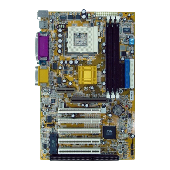
VIA 82C694 ATX Mainboard INTRODUCTION MAINBOARD LAYOUT PS/2 Game/MIDI USB1 Parallel Port Mouse Port USB2 COM1 COM 2 Audio Port... -
Page 7: Specifications
¥ WORD SIZE Data Path 8-bit, 16-bit, 32-bit, 64-bit Address Path 32-bit ¥ PC SYSTEM CHIPSET 694AX and 694AXL: VIA VT82C694X and VT82C686A chipset 694BX and 694BXL: VIA VT82C694X and VT82C686B chipset ¥ FRONT SIDE BUS FREQUENCY 66 MHz 100MHz and 133MHz.. -
Page 8: Hardware Monitoring
Two channels of Ultra DMA IDE ports designed on the board, which will support up to 4 IDE devices like IDE hard disk, ATAPI CD-ROM and LS-120/ZIP-100 devices. 694AX and 694AXL: Support Ultra DMA 33/66 694BX and 694BXL: Support Ultra DMA 33/66/100 ¥ SUPER I/O PORTS 1. - Page 9 VIA 82C694 ATX Mainboard INTRODUCTION ¥ ACPI Advanced Configuration and Power Interface (ACPI) function is strongly recommended by PC’98 because it will let you have many additional features and that will make your PC system becomes very friendly and convenient. Followings are the ACPI features designed on the board: 1.
-
Page 10: Installation
VIA 82C694 ATX Mainboard INSTALLATION 2. INSTALLATION UNPACKING The mainboard contains the following components. Please inspect the following contents and confirm that everything is there in the package. If anything is missing or damaged, call your supplier for instructions before proceeding. 2 2 2 2 Mainboard 2 2 2 2... -
Page 11: Quick Installation
VIA 82C694 ATX Mainboard INSTALLATION 2.2 QUICK INSTALLATION This section provides a quick installation guide. If you do not have enough experience to install the mainboard the PC system correctly, please refer to the following procedures to install your PC system: 1. -
Page 12: Amazing Ways To Power On The Pc System
VIA 82C694 ATX Mainboard INSTALLATION 2.3 AMAZING WAYS TO POWER ON THE PC SYSTEM When the mainboard has been installed successfully, there are several ways to power on the system. Please read the following description for all the details. ¨ POWER BUTTON The power button can be programmed by COMS setup program and it has different features. -
Page 13: Power Off The Pc System
VIA 82C694 ATX Mainboard INSTALLATION ( COM1 or COM2 ) on the mainboard. When the mainboard detects the ring-in signal from the serial port, the system power will be turned on and start to receive the incoming messages automatically. ( you need to have the software like Award Zero-Volt Data-Suspend Utility so that you can use the fax utility to receive the incoming fax message ). -
Page 14: Hardware Setup
VIA 82C694 ATX Mainboard HARDWARE SETUP 3. HARDWARE SETUP Before you can start to install this mainboard, some hardware setting is required so that it will work perfectly. To configure the mainboard is a simple task, only a few jumpers, connectors, cables and sockets need to be selected and configured. This section will show all the connectors and jumpers on the mainboard. -
Page 15: Install The Dram Modules
VIA 82C694 ATX Mainboard HARDWARE SETUP 3.2 INSTALL THE DRAM MODULES This mainboard has three DIMM sockets designed on the mainboard and you can use the single-side or double-side DIMM module on the mainboard. DIMM 3 DIMM 2 DIMM 1 Picture of Memory sub-system. -
Page 16: Connectors
VIA 82C694 ATX Mainboard HARDWARE SETUP CONNECTORS The connectors on the mainboard are either the pin header type or D-type connectors, they are used to connect the accessories or peripheral devices (such as power, mouse, printer,...etc.). Followings are the connectors with its description and the pin assignment which is designed on the mainboard. - Page 17 VIA 82C694 ATX Mainboard HARDWARE SETUP (C) CN3 : Serial Port COM 1 Connector (D) CN4 : Serial Port COM 2 Connector COM 1 COM 2 (I/O address: 3F8H/2F8H/3E8H/2E8H, IRQ3/IRQ4, selected by CMOS setup.) (E) CN5: Parallel Port Connector (Supports SPP/EPP/ECP modes, IRQ7 or IRQ5 is selectable, ECP mode will use either DMA channel 3 or channel 1 which can be selected by the CMOS setup probram) PARALLEL PORT...
- Page 18 VIA 82C694 ATX Mainboard HARDWARE SETUP (F) CN6: USB Port 1 (Universal Serial Bus) Connector (G) CN7: USB Port 2 (Universal Serial Bus) Connector USB 1 USB 2 (H) CN8: Floppy Disk Control Port Connector (IRQ6, DMA channel 2) CN8: FDC Connector...
- Page 19 VIA 82C694 ATX Mainboard HARDWARE SETUP (I) CN9 : IDE 1 Connectors (Primary IDE Port: 1F0H, IRQ 14) (J) CN10: IDE 2 Connectors (Secondary IDE Port: 170H, IRQ 15) CN9: IDE 1 CN10: IDE 2 (K) CN12: IR (Infrared Rays) Connector +5VDC NO CONNECTION IR RECEIVE...
- Page 20 VIA 82C694 ATX Mainboard HARDWARE SETUP (L) CN13: CPU Cooling Fan Power Connector (Fan 1) CN13 +12V Fan Signal (M) CN15: ATX Power Connector CN15 ATX Power connector (N) CN16: WOL (Wake On LAN) Connector...
- Page 21 VIA 82C694 ATX Mainboard HARDWARE SETUP In order to use the WOL LAN card to trigger the power of the PC system, the switching power supply must be able to provide at least 700mA current driving ability on the “5V standby” voltage. 5V Standby CN 16 Ground...
- Page 22 VIA 82C694 ATX Mainboard HARDWARE SETUP The is the 3D audio interface is the optional choice for customers. If you find the CN18 installed, there is the 3D audio function included on the board. 1. SPK_OUT CN18 2. LINE_IN 3. MIC._IN 4.
- Page 23 VIA 82C694 ATX Mainboard HARDWARE SETUP (S) CN31: USB Port 4 (Universal Serial Bus) Connector In order to connect the USB device, you will need to have the USB cable connected to the CN30 and CN31. Wrong USB cable may cause serious damage to this mainboard.
- Page 24 VIA 82C694 ATX Mainboard HARDWARE SETUP (T) Push buttons and LED connectors A series of connectors are designed on the board to connect the push buttons and LED indicators. Followings are the details: RS: Reset Button connector HL: HDD LED connector SL: Sleep LED connector PW: Power On / Off Suspend switch SL HL RS...
- Page 25 VIA 82C694 ATX Mainboard HARDWARE SETUP Power On / Off and External Suspend Switch Connector According to the setup in CMOS, the PW connector has two functions. It can be the Power Switch or Suspend Switch of your PC system. (please refer to the Aware BIOS setup in Section 4) ...
- Page 26 VIA 82C694 ATX Mainboard HARDWARE SETUP (U) Speaker and Power LED connector: 1 2 3 4 1 2 3 4 PWRLED Speaker & Power LED Connectors SPK: Speaker connector Pin # Signal name + 5V DC No Connection No Connection Speaker Data Signal PWRLED: Front Panel Power LED and Key-Lock Connector...
- Page 27 VIA 82C694 ATX Mainboard HARDWARE SETUP Sleep LED Sleep LED is designed to indicate the status of the PC system. When the PC system is powered on, the sleep LED will be darkened. When the power of the PC system is OFF, the sleep LED will be lightened to indicate the PC system is now under sleep mode.
-
Page 28: Jumpers
VIA 82C694 ATX Mainboard HARDWARE SETUP 3.4 JUMPERS This section will discuss the jumper setting on the mainboard. In order to let you have better idea of the jumper setting, please see below for the explanation of jumper settings before you start this section. open short A jumper is a set of two, three or more jumper pins which allow users to make different... - Page 29 VIA 82C694 ATX Mainboard HARDWARE SETUP (B) JP9: CMOS Data Clear Button 1-2 Short: Normal Setting. 2-3 Short: Clear CMOS. 1 2 3 Basically, the BIOS setup program will have all the setting saved in the CMOS memory which is included in the core logic of the mainboard. If you want to clear the setting which is saved in the CMOS memory, you may use JP9 and refer to the following procedure to clear the information in the CMOS.
- Page 30 VIA 82C694 ATX Mainboard HARDWARE SETUP (C) SW1: CPU Front Side Bus (FSB) Speed Selection (optional choice) SW1 is designed on the mainboard to select the CPU FSB speed. Please refer to the following for the settings: FSB Clock SW 1-1 SW 1-2 SW 1-3 SW 1-4...
- Page 31 VIA 82C694 ATX Mainboard HARDWARE SETUP (D) SW2: CPU Clock Ratio Selection (optional choice) SW2 is designed on the mainboard to select the CPU clock ratio. Basically, the CPU clock ratio will be decided by the CPU automatically. When you have installed the CPU onto the mainboard, the CPU clock ratio is decided automatically and you can not use the switch setting on SW2 to change the clock ratio.
-
Page 32: Installation Of Device Drivers
VIA 82C694 ATX Mainboard HARDWARE SETUP 3.5 INSTALLATION OF DEVICE DRIVERS IMPORTANT NOTE: Please refer to the following sequence to install the related device drivers: 1. Install the device drivers for the mainboard. 2. Install the device driver for the onboard sound interface. 3. -
Page 33: Award Bios Setup
VIA 82C694 ATX Mainboard AWARD BIOS SETUP AWARD BIOS SETUP 4.1 GETTING STARTED When you turn the system powered on or reset the PC system, the system BIOS will enter the POST routines (Power On Self Test routines). POST will execute a series of diagnostics and system initialization, and you will see the copyright message displayed on the screen.) In case that there is any error or malfunction detected, the BIOS will give a series of beeping sound or display the error message on screen. -
Page 34: Main Menu
VIA 82C694 ATX Mainboard AWARD BIOS SETUP 4.3 MAIN MENU ROM PCI / ISA BIOS (2A69KXXX) CMOS SETUP UTILITY AWARD SOFTWARE, INC. Standard CMOS Setup Frequency / Voltage Control Advanced BIOS Features Load Optimized Defaults Advanced Chipset Features Set Supervisor Password Integrated Peripherals Set User Password Power Management Setup... -
Page 35: Standard Cmos Setup
VIA 82C694 ATX Mainboard AWARD BIOS SETUP 4.4 STANDARD CMOS SETUP CMOS Setup Utility - Coryright ( C ) 1984 - 2000 Award Software. Date (mm : dd : yy) : Mon, 10 2000 Item Help Time (hh : mm : ss : 16 : 03 : 33 Menu Level IDE Primary Master Quantum Fireball CX13... -
Page 36: Advanced Bios Features
VIA 82C694 ATX Mainboard AWARD BIOS SETUP 4.5 ADVANCED BIOS FEATURES CMOS Setup Utility - Coryright ( C ) 1984 - 2000 Award Software. Advanced BIOS Features Virus Warning :Disabled Item Help CPU Internal Cache : Enabled Ø External Cache : Enabled Menu Level CPU L2 Cache ECC Checking... - Page 37 VIA 82C694 ATX Mainboard AWARD BIOS SETUP Virus Warning : This is the virus intruding warning feature in the BIOS. During and after the operation system is loaded, any attempt to write to the boot sector or partition table on the IDE hard disk drive will trigger this feature and give you some warning messages on the screen and then halt the system.
- Page 38 VIA 82C694 ATX Mainboard AWARD BIOS SETUP Boot Up Floppy Seek When enabled, the floppy drive will be initialized during POST. Boot Up NumLock Status : When enabled, the NumLock LED will be lightened after the POST. Security Option : This selection field allows you to select how to secure the PC system for you.
-
Page 39: Advanced Chipset Features
VIA 82C694 ATX Mainboard AWARD BIOS SETUP 4.6 ADVANCED CHIPSET FEATURES CMOS Setup Utility - Copyright (C) 1984 - 1999 Award Software Advanced Chipset Features DRAM Timing By SPD Disabled Item Help DRAM Clock CPU Clock Ø SDRAM Cycle Length Menu Level Bank Interleave Disabled... - Page 40 VIA 82C694 ATX Mainboard AWARD BIOS SETUP DRAM Timing By SPD When enabled, the system BIOS will read the DRAM parameters from the SPD chip on the DIMM module and set the DRAM timing automatically. DRAM Clock This field allows you to select the DRAM access speed to control the memory performance.
- Page 41 VIA 82C694 ATX Mainboard AWARD BIOS SETUP AGP Aperture Size Select the size of Accelerated Graphics Port (AGP) aperture. The aperture is a portion of the PCI memory address range dedicated for graphics memory address space. Host cycles that hit the aperture range are forwarded to the AGP without any translation.
- Page 42 VIA 82C694 ATX Mainboard AWARD BIOS SETUP PCI Dynamic Bursting When Enabled, every write transaction goes to the write buffer. Burstable transactions then burst on the PCI bus and nonburstable transactions don’t. PCI Master 0 WS Write When Enabled, writes to the PCI bus are executed with zero wait states. PCI Delay Transaction The chipset has an embedded 32-bit posted write buffer to support delay transactions cycles.
-
Page 43: Integrated Peripherals
VIA 82C694 ATX Mainboard AWARD BIOS SETUP 4.7 INTEGRATED PERIPHERALS CMOS Setup Utility - Copyright (C) 1984 - 1999 Award Software Integrated Peripherals On-Chip IDE Chanel0 Enabled Item Help On-Chip IDE Chanel1 Enabled Ø IDE Prefetch Mode Enabled Menu Level Primary Master PIO Auto Primary Slave PIO... - Page 44 VIA 82C694 ATX Mainboard AWARD BIOS SETUP IDE Prefetch Mode The onboard IDE drive interfaces supports IDE prefetching for faster drive accesses. If you install a primary and/or secondary add-in IDE interface, set this field to Disabled if the interface does not support prefetching. Primary/Secondary, Master/Slave PIO The four IDE PIO (Programmed Input/Output) fields let you set a PIO mode (0-4) for each of the four IDE devices that the onboard IDE interface supports.
- Page 45 VIA 82C694 ATX Mainboard AWARD BIOS SETUP IR Function Duplex This item allows you to select the IR half/full duplex funcion. TX,RX inverting enable This item allow you to enable the TX, RX inverting which depends on different H/W requirement. This field is not recommended to change its default setting for avoiding any error in your system.
-
Page 46: Power Management Setup
VIA 82C694 ATX Mainboard AWARD BIOS SETUP POWER MANAGEMENT SETUP CMOS Setup Utility - Copyright (C) 1984 - 1999 Award Software Power Management Setup ACPI Function Disabled Item Help Ø Power Management Press Enter Menu Level PM Control By APM Video Off Option Suspend ->... - Page 47 VIA 82C694 ATX Mainboard AWARD BIOS SETUP Disable No power management. Disable all power saving modes. Minimum power management. Doze Mode = 1 hr. Min. Power Saving Standby Mode = 1 hr., Suspend Mode = 1 hr., and HDD Power Down = 15 min. Maximum power management -- ONLY AVAILABLE Max.
- Page 48 VIA 82C694 ATX Mainboard AWARD BIOS SETUP mode. Always On Monitor will remain on during power saving modes. Suspend --> Off Monitor blanked when the systems enters the Suspend mode. Susp,Stby --> Off Monitor blanked when the system enters either Suspend or Standby modes.
- Page 49 VIA 82C694 ATX Mainboard AWARD BIOS SETUP Pressing the power button for more than 4 seconds forces the system to enter the Soft-Off state when the system has “hung.”. Suspend Type: (Default setting: "Stop Grant" ) This field allows to select the suspend type, you can choose the CPU Stopy Grand Suspend or the PwrOn Suspend.
- Page 50 VIA 82C694 ATX Mainboard AWARD BIOS SETUP Modem / Lan Resume An input signal on the serial Ring Indicator (RI) line (in other words, an incoming call on the modem) awakens the system from a soft off state. Date (of Month) Resume Time (hh:mm:ss) WhenRTC Alarm Resume is enabled, your can set the date and time at which the RTC (real-time clock) alarm awakens the system from Suspend mode.
-
Page 51: Pnp/Pci Configuration
VIA 82C694 ATX Mainboard AWARD BIOS SETUP 4.9 PNP/PCI CONFIGURATION CMOS Setup Utility - Copyright (C) 1984 - 1999 Award Software PnP/PCI Configuration PnP OS Installed Item Help Reset Configuration Data : Disabled Ø Resources Controlled By : Auto (ESCD) Menu Level IRQ Resources : Press Enter... - Page 52 VIA 82C694 ATX Mainboard AWARD BIOS SETUP When resources are controlled manually, assign each system interrupt a type, depending on the type of device using the interrupt Legacy ISA Devices compliant with the original PC AT bus specification, requiring a specific interrupt ( such as IRQ4 for serial port 1). PCI/ISA PnP Devices compliant with the Plug and Play standard, whether designed for PCI or ISA bus architecture.
-
Page 53: Pc Health Status
VIA 82C694 ATX Mainboard AWARD BIOS SETUP 4.10 PC HEALTH STATUS CMOS Setup Utility - Copyright (C) 1984 - 1999 Award Software PC Health Status Current CPU Temp. C/134 Item Help Current System Temp. C/77 Ø Current CPUFAN1 Speed 5904 RPM Menu Level Current CPUFAN2 Speed 0 RPM... -
Page 54: Frequency/Voltage Control
VIA 82C694 ATX Mainboard AWARD BIOS SETUP 4.11 FREQUENCY/VOLTAGE CONTROL CMOS Setup Utility - Copyright (C) 1984 - 1999 Award Software Frequency/Voltage Control Auto Detact DIMM/PCI Clk Disabled Item Help Spread Spectrum Disabled Ø CPU Host / PCI Clock 100 /33 MHz Menu Level CPU Vcore Select Default... - Page 55 VIA 82C694 ATX Mainboard AWARD BIOS SETUP CPU Vcore Select This selection field allows you to fine tune the CPU core voltage. When you use this field to fine tune the CPU core voltage, you will see a selection table appeared as shown below: Auto Detact DIMM/PCI Clk Disabled...
-
Page 56: Load Optimized Defaults
VIA 82C694 ATX Mainboard AWARD BIOS SETUP 4.12 LOAD OPTIMIZED DEFAULTS CMOS Setup Utility - Copyright (C) 1984 - 1999 Award Software Standard CMOS Features Frequency / Voltage Control Advanced BIOS Features Load Optimized Defaults Advanced Chipset Features Set Supervisor Password Integrated Peripherals Set User Password Power Management Setup... -
Page 57: Set Supervisor Password
VIA 82C694 ATX Mainboard AWARD BIOS SETUP 4.13 SET SUPERVISOR PASSWORD CMOS Setup Utility - Copyright (C) 1984 - 1999 Award Software Standard CMOS Features Frequency / Voltage Control Advanced BIOS Features Load Optimized Defaults Advanced Chipset Features Set Supervisor Password Integrated Peripherals Set User Password Power Management Setup... -
Page 58: Set User Password
VIA 82C694 ATX Mainboard AWARD BIOS SETUP 4.14 SET USER PASSWORD CMOS Setup Utility - Copyright (C) 1984 - 1999 Award Software Standard CMOS Features Frequency / Voltage Control Advanced BIOS Features Load Optimized Defaults Advanced Chipset Features Set Supervisor Password Integrated Peripherals Set User Password Power Management Setup... - Page 59 VIA 82C694 ATX Mainboard AWARD BIOS SETUP B. When there is no password stored in the "SUPERVISOR PASSWORD" 1. When "Setup" is selected in Security Option: Users can use the "User Password" to log into the BIOS setup program, and they can make all the change in the BIOS setup program.
-
Page 60: Save & Exit Setup / Exit Without Saving
VIA 82C694 ATX Mainboard AWARD BIOS SETUP 4.15 SAVE & EXIT SETUP / EXIT WITHOUT SAVING CMOS Setup Utility - Copyright (C) 1984 - 1999 Award Software Standard CMOS Features Frequency / Voltage Control Advanced BIOS Features Load Optimized Defaults Advanced Chipset Features Set Supervisor Password Integrated Peripherals... -
Page 61: How To Update The System Bios
VIA 82C693 BIOS UPDATE MAINBOARD 5. How to Update the System BIOS Before we start to discuss system BIOS update, there are some important issues which you need to pay attention on it: 1. You can not exchange the system BIOS with another mainboard: The system BIOS on different mainboard are different. - Page 62 3. Down load “AWDFLASH.EXE” program. 4. Scroll the screen downward and find the 694AX or 694BX mainboard. 5. Select the BIOS and start to down load. (the file name for 694AX and 694BX is 694XW.BIN. The file name for 694AXL and 694BXL is 694XLW.BIN)
- Page 63 VIA 82C694 ATX Mainboard BIOS UPDATE Step 3. Start to update the system BIOS: 1. Have the diskette which we made in Step 2 inserted in the floppy disk drive.. 2. Start the PC system and click on the “del” key to start the BIOS setup program.
Need help?
Do you have a question about the 694AX and is the answer not in the manual?
Questions and answers