Table of Contents
Advertisement
Quick Links
EFFECTIVE DATE 06-2011
Rev. 07
OPERATION, MAINTENANCE
OPERATION, MAINTENANCE
& INSTALLATION MANUAL
& INSTALLATION MANUAL
For
For
"ELXC" AND "ELXC-UV" SERIES
"ELXC" AND "ELXC-UVi" SERIES
VENTILATORS
VENTILATORS
GAYLORD INDUSTRIES
10900 S.W. AVERY STREET - TUALATIN, OREGON 97062 U.S.A.
10900 S.W. AVERY STREET • TUALATIN, OREGON 97062 U.S.A.
email: info@gaylordventilation.com - 800-547-9696 - FAX: 503-692-6048
800-547-9696 • 503-691-2010 • FAX: 503-692-6048 • email: info@gaylordusa.com
www.gaylordventilation.com
Advertisement
Table of Contents

Related Manuals for GAYLORD ELXC Series


Summary of Contents for GAYLORD ELXC Series
- Page 1 “ELXC” AND “ELXC-UV” SERIES “ELXC” AND “ELXC-UVi” SERIES VENTILATORS VENTILATORS GAYLORD INDUSTRIES 10900 S.W. AVERY STREET - TUALATIN, OREGON 97062 U.S.A. 10900 S.W. AVERY STREET • TUALATIN, OREGON 97062 U.S.A. email: info@gaylordventilation.com - 800-547-9696 - FAX: 503-692-6048 800-547-9696 • 503-691-2010 • FAX: 503-692-6048 • email: info@gaylordusa.com...
- Page 2 RETRIEVAL SYSTEM, OR TRANSMITTED IN ANY FORM BY AN ELECTRIC, MECHANICAL, PHOTOCOPYING, RECORDING MEANS OR OTHERWISE WITHOUT PRIOR WRITTEN PERMISSION OF GAYLORD INDUSTRIES. COPYRIGHT 2011. © Copyright 2011, Gaylord Industries The manufacturer reserves the right to modify the materials and specifications resulting from a continuing program of product improvement or the availability of new materials.
- Page 3 If you have any questions, please contact us at info@gaylordventilation.com or by calling us toll free 800-547-9696. We are more than happy to help. Sincerely, Gaylord Industries Gaylord Industries 10900 SW Avery Street Tualatin, OR 97062 www.gaylordventilation.com...
-
Page 4: Table Of Contents
Model Number Sequence ………………………………………………………………………………………………. Chapter 2 – Principles of Operation ELXC Series - Turning on the Exhaust Fan ................ELXC Series - Turning off the Exhaust Fan ………………….………………………………………………………… ELXC Series - Wash Cycle ………………………………………………………………………………………………..…… ELXC Series - Fire Protection ……………………………………………………………………………………………..…... - Page 5 Operation and Maintenance Manual for the Gaylord Command Center. 2. ELX and ELX-UVi Ventilators may include a Gaylord “Capture Wall” option. The specific manual for installation of this is titled Installation Manual – ELX Ventilators with Capture Wall.
-
Page 6: Model Description
Chapter 1 - Introduction Model Description Overview The Gaylord Model ELXC Series Ventilator is a high grease extraction efficiency Ventilator that incorporates a hot water Wash Cycle that automatically washes the accumulated grease out of the Ventilator and into the building drain system. The Model ELXC-UVi Series includes the additional feature of an Ultraviolet Light System that dramatically reduces grease accumulation in the exhaust plenum, ductwork and fans. -
Page 7: Model Number Sequence
Chapter 1 - Introduction Model Number Sequence Gaylord Ventilator model numbers are made up of an alphabetic prefix followed by a series of alphabetic and/or numeric suffixes to designate the style of ventilator and various options. Sequence of model num- bers is as follows. - Page 8 A ......Hood to have an apron, which will terminate at the bottom lower edge of the canopy. (No interconnecting drains). UW ......Gaylord UDS to be incorporated into capture wall. (Mixed Intertek and UL listing required). Chapter 1 - Introduction Definition of Prefixes and Suffixes –...
- Page 9 (Refer to Figure 2-2-2). Operation of the exhaust fan is controlled by the Gaylord Command Center, which is mounted in the Wash Control Cabinet (refer to Figure 2-2-1). To start the exhaust fan push “START FAN” on the Command Center.
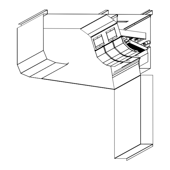
- Page 10 Chapter 2 - Principles of Operation ELXC Series - Cont. Command Center Figure 2-2-1 Wash Control Cabinet Balancing Damper Autostart Sensor Gaylord Model XGS Extractors Extractor Access Door Grease Canal Inlet Slot Grease Gutter Grease Laden Air Drain Figure 2-2-2...
- Page 11 Wash Cycle - Overview The ELXC Series is referred to as a clean in place Ventilator as it has automatic Wash Cycles that washes away the extracted grease within the Extractors, Plenum and surrounding areas, with hot, detergent injected wa- ter.
- Page 12 Chapter 2 - Principles of Operation ELXC Series - Cont. Wash Cycle Sequence – Cont. The frequency and the length of the Wash Cycle is determined by the type of cooking equipment involved; Light Duty, Light/Medium Duty, Medium Duty, Heavy Duty, and Extra Heavy Duty. Refer to Table T-2-16-1, Typical Example of Frequency and Length of Wash Cycles, on page 2-16 for typical application.
- Page 13 If the Fire Extinguishing System is wired to a building management system it will notify of a fire con- dition. The Fire Extinguishing System should be wired to the Gaylord Command Center. If it is, the following will occur: If the exhaust and supply fan were on the exhaust fan would stay on and the supply fan would shut off.
- Page 14 Fire Extnguishing System Duct Detector Fire Extinguishing System ° Cooking Equipment F Thermostat Detectors Used only when a Gaylord Fire Balancing Damper (Model GFBD) is used. Fire Extinguishing System Plenum Nozzle(s) Fire Extinguishing System Cooking Equipment Nozzles *Illustration shows Fire Extinguishing System discharging.
- Page 15 (Refer to Figure 2-10-1). Operation of the exhaust fan and UV Lamps is controlled by the Gaylord Command Center (refer to Figure 2-9-1). To start the exhaust fan and turn on the UV Lamps push the “START FAN” button on the Command Center.
- Page 16 UVi System Standby mode until the cause has been corrected. In addition to the Status Lights on the Ventilator, the Gaylord Command Center displays text indicating a simi- lar message as the Status Lights. Refer to the Operation and Maintenance Manual for the Gaylord Command Center for complete operational instructions.
- Page 17 ELXC-UVi Series - Cont. Grease Extraction Grease is removed from the exhaust air by combination of the Gaylord Model XGS Extractors and the UV Lamps (Refer to Figure 2-10-1). The hot contaminate-laden air rising from the cooking surface enters the inlet slot, turns and is drawn through the Extractors where a high percentage of the grease and other par- ticulate are extracted from the airstream.
- Page 18 At the end of the cooking day, turn off the cooking equipment and allow to cool before turning off the ex- haust fan. To turn off the exhaust fan and UV Lamps push the “STOP FAN” button on the Gaylord Command Center (Refer to Figure 2-9-1).
- Page 19 Turning Off the Exhaust Fan - Cont. Note 1: If the Ventilator is equipped with a Gaylord Autostart Controller, the exhaust fan will stay on if the temperature at the sensor mounted in the canopy exceeds 90°F. (Refer to Figure 2-10-1). Once the tempera- ture drops below 90°F., the fan will continue to run for 15 minutes and then shut off.
- Page 20 Chapter 2 - Principles of Operation ELXC-UVi Series - Cont. Wash Cycle Sequence – Cont. Wash Cycle Example Extractor Wash Cycle – The Extractor Wash Cycle only comes on while the exhaust fan is on, typically dur- ing cooking (Refer to Figure 2-12-1). Using Table T-2-16-1 on page 2-16, if the cooking equipment under the Ventilator is Heavy Duty then the Extractor Wash would come on every 4 hours of fan operation, stay on for 3 minutes and then shut off.
- Page 21 4. If the Fire Extinguishing System is wired to a building management system it will notify of a fire condi- tion. 5. The Fire Extinguishing System should be wired to the Gaylord Command Center. If it is, the following will occur: a) If the exhaust and supply fan were on the exhaust fan would stay on and the supply fan would shut off.
- Page 22 Fire Extinguishing System Duct Nozzle Fire Extinguishing System Duct Detector Fire Extinguishing 250*F Thermostat System Used only when a Gaylord Fire Cooking Equipment Balancing Damper (Model GFBD) Detectors is used. UV Module Fire Extinguishing System Plenum Nozzle(s) Fire Extinguishing System Cooking Equipment Nozzles *Illustration shows Fire Extinguishing System discharging.
- Page 23 Wash System Overview The wash system is controlled by the Gaylord Command Center. The Command Center is mounted in the Wash Control Cabinet which houses the valves, detergent pump, detergent tank and other plumbing com- ponents needed to operate the Wash Cycles (refer to Figure 2-15-1). In addition, two solenoid valves are located on the top or near the top of each Ventilator section (refer to page A-5-1 for an illustration).
- Page 24 4 hours and the Plenum Wash from 36 hours to 16 hours. Refer to the Operation and Maintenance Manual for the Gaylord Command Center for instructions on programming the times. Refer to the Troubleshooting section page 4-2 for possible causes of inadequate cleaning.
- Page 25 Plenum Wash, the Wash Cycle for Ventilator section #2 would immediately begin or it can be delayed by programming the Command Center. The delay can be programmed for up to 99 minutes. Refer to the Op- eration and Maintenance Manual for the Gaylord Command Center for complete programming instructions. Table T-2-17-1...
- Page 26 2010 Products, Inc. warrants that Formula G-510EF will not cause cleansing agent damage to the rubber and synthetic parts of the injection pump (“O” rings, diaphragms, washers, tubing, and other such parts) used with The Gaylord Ventilator, Heat Reclaim Unit, or Pollution Control Equipment so long as used pursuant to its product instructions.
- Page 27 Balancing Dampers Balancing Dampers Overview The ELXC and ELXC-UVi Series Ventilators, as a standard, come with one of three models of Gaylord Indus- tries Listed Balancing Dampers. Balancing dampers would typically be used when two or more Ventilators are connected to a common exhaust fan. The purpose of the balancing damper is to raise or lower the airflow of each Ventilator to achieve the desired exhaust rate.
- Page 28 Chapter 2 - Principles of Operation Balancing Dampers - Cont. Figure 2-20-1 Figure 2-20-2 Typical Model GEBD Section View of Model GBD Other Models Look Similar The Dampers and the DSD Except Without the Motor are the same for all Models (%) OPEN DSD (in 4-1/16...
-
Page 29: Chapter 3 - Maintenance
Operator Preventive Maintenance Overview To maintain the Gaylord Ventilator in good working order and to keep the system operating at optimum ef- ficiency, preventive maintenance, using the following schedule, should be performed. Important Note: Ventilators incorporating UV Lamps require special maintenance as shown on page 3-3. - Page 30 Chapter 3 - Maintenance Operator Preventive Maintenance - Cont. Inspection and Cleaning Requirements NFPA-96 (Standard for Ventilation Control and Fire Protection of Commercial Cooking Operations) require that hoods (Ventilators), ducts and exhaust fans must be inspected by a properly trained, qualified and certi- fied company or person(s) in accordance with the following table.
-
Page 31: Uv System Scheduled Preventive Maintenance
Access Doors in place and latched.) a. Turn on the exhaust fan at the Gaylord Command Center. The “UVi SYSTEM ON” green Status Light in each Ventilator Section should be on. In addition to the Status Lights on the Ventilator, the Gaylord... - Page 32 Chapter 3 - Maintenance UV System Scheduled Preventive Maintenance - Cont. Testing UV Lamps and Ballasts - Cont. b. If the yellow “UVi LAMP FAILURE” Status Light is on it indicates that one or more of the UV Lamps are not operating. To troubleshoot and replace a lamp refer to the Troubleshooting page 4-4, and Testing and Repair section of this manual beginning on page 5-7.
- Page 33 The UV Lamps need to be replaced after 13,000 hours of use. After 13,000 hours the Lamps will still work but the performance of the Lamps decreases dramatically. The Gaylord Command Center has a built-in UV hours of operation clock. Refer to the Operation and Maintenance Manual for the Gaylord Command Center for complete operational instructions.
- Page 34 Chapter 3 - Maintenance Opening Extractor Access Door To open the Extractor Access Doors proceed as follows: 1. Place your hands around the lower edge of the door as shown below. Pull the door out and slightly up until the hinge pin lines up with the vertical slot and the door drops down approximately 1/2”. 2.
-
Page 35: Chapter 4 - Troubleshooting
3 Check for proper size of exhaust fan. Fan must deliver 1 through 5-4. Ventilator Nameplate rating. 4 Check and adjust Gaylord Balancing Damper as described pages 2-19 of this manual. 5 Check for open access panel in duct system and close or re-install if open. - Page 36 H. Detergent pump has lost it's prime or is 1 Refer to the Operation, Maintenance and Installation malfunctioning. Manual for the Gaylord Command Center and Wash Control Cabinet, the Troubleshooting section. I. Clogged Spray Nozzle(s). 1 To determine if there are clogged spray nozzles refer to...
- Page 37 B. Malfunction PLC control in the Command 1 Refer to the Operation, Maintenance and Installation Center control. Manual for the Gaylord Command Center and Wash Control Cabinet, the Troubleshooting section. Extractor Wash or Plenum Wash is spraying Water Solenoid Valve is stuck in the open Gently tap the valve housing with a hammer.
- Page 38 6 Command Center not functioning as A. Varies. 1 Refer to Operation, Maintenance and Installation intended. Manual for the Gaylord Command Center and Wash Control Cabinet, the Troubleshooting section.
-
Page 39: Ventilator Control Matrix
The exhaust and supply fans and UV Lamps will continue to operate for a 15 minute cool down time and then shut off. Note 4 The Gaylord Electric Balancing Damper or The Gaylord Fire Balancing Damper will close after the 15 minute cool down time. The Dampers are always open when the exhaust fan is on. Note 5: Chemical Fire Extinguishing Systems are listed to extinguishing a fire with or without the exhaust fan on. - Page 40 INTENTIONALLY LEFT BLANK...
-
Page 41: Chapter 5 - Testing And Repair
This method requires an Anemometer and the recommended unit is a Pacer rotating vain Model DA40 or DA4000 Digital Anemometer. These instruments can be purchased from Gaylord Industries. To measure the air inlet velocity and confirm the exhaust volume, proceed as follows: Instructions 1. - Page 42 Chapter 5 - Testing and Repair Measuring Airflow - Cont. 10. At the end of 16 seconds an average velocity will appear on digital readout of the meter. 11. Record the average velocity (FPM). 12. Repeat the process for any additional Ventilator sections. 13.
- Page 43 Chapter 5 - Testing and Repair Measuring Airflow - Cont. Figure 5-3-1 Sensing Head at Air Inlet Slot Figure 5-3-2 Anemometer...
- Page 44 1037 1065 1129 1147 1175 1290 1. REFER TO GAYLORD VENTILATOR TECHNICAL MANUAL FOR METHOD(S) OF VERIFYING AIR VOLUMES. 2. ELECTRICAL RATING OF LIGHT FIXTURES; 120 VOLT, 60HZ. OR 220 VOLT 50HZ OVERALL RATING - 12 AMPS OR LESS 3. IF HOOD IS EQUIPED WITH ULTRAVIOLET LAMP...
- Page 45 Measuring Airflow - Cont. Capture Performance All Gaylord Ventilators are factory engineered to operate at a specific exhaust volume, CFM (Cubic Feet per Min- ute), based on, primarily, the type of cooking appliance, and the exact model of the Ventilator. Capture perfor- mance is based on two primary functions, 1) the ventilator is exhausting the engineered CFM and 2) the make-up air is being introduced correctly.
-
Page 46: Makeup Air Guidelines
Make- Up Air Guidelines Following these guidelines will result in proper cap- ture and containment at the Ventilator and enact the Gaylord Capture Performance Guarantee. If jobsite conditions cannot accommodate these guidelines, consult Gaylord Industries for alternative design. Figure 5-6-1... -
Page 47: Replacing Uv Lamps
DANGER: Replacing UV Lamps as outlined on this page MUST be performed by a Gaylord Certified DANGER: Replacing UV Lamps as outlined on this page MUST be performed by a Gaylord Certified Service Service Agent. For a list of Gaylord Certified Service Agencies (CSA’s) visit www.gaylordusa.com... - Page 48 Instructions for Replacing UV Lamps To replace UV lamps carefully use the following step by step instructions. 1. Turn off all power to the Gaylord Command Center. 2. Turn off all circuits that supply power to the UV Lamps. 3. Open the UV Module Access Door (Refer to Figure 5-9-1).
- Page 49 Chapter 5 - Testing and Repair Replacing UV Lamps - Cont. UV Status Lights AutoStart Sensor Static Tap Opening UV Lamp Module UV Lamps Extractor Access to Ballast Box UV Module Access Door Extractor Access Door Figure 5-9-1 Lamp #1 Lamp #2 Lamp #3 Lamp #4...
-
Page 50: Replacing Uv Lamp Sockets
Lamp Sockets, the Individual Method or the Wiring Harness Method. Use the following directions for replac- ing: DANGER: Replacing UV Lamp Sockets as outlined on the following pages MUST be performed by a Gaylord Certified Service Agent. For a list of Gaylord Certified Service Agencies (CSA’s) visit www.gaylordventilation.com and go to “Service Agencies”... - Page 51 Do not pull the UV Lamp Long Wire at this time. It is needed to pull the new Lamp Socket through the conduit. 12. Using a Pin Removal Tool, Gaylord Part Number 20415, push the associated pin out of the base of the Pined Receptacle.
- Page 52 Instructions for Replacing UV Lamp Sockets – Wiring Harness Method DANGER: Replacing UV Lamp Sockets as outlined on this page MUST be performed by a Gaylord Certified Service Agent. For a list of Gaylord Certified Service Agencies (CSA’s) visit www.gaylordventilation.com and go to “Service Agencies”...
- Page 53 20. Close the UV Module Access Door. 21. Turn on all circuits that supply power to the UV Lamps. 22. Turn on power to the Gaylord Command Center. 23. Check for proper operation of the UV Lamps and Pressure Switches following the Test Lamps and Ballasts instructions on page 3-3.
- Page 54 Chapter 5 - Testing and Repair UV Ballast Box Overview There is one UV Ballast Box for each Ventilator section. The UV Ballast Box contains the Ballasts and other electrical components necessary to operate the UV System (Refer to Figure 5-20-2). A list of all the compo- nents and their part numbers are shown on Page 6-7 and 6-8.
- Page 55 Caution: Turn off all power to the Command Center and to the UV Ballast Box. There is a risk of shock, injury, and /or death from contact with live electrical components. 1. Turn off all power to the Gaylord Command Center. 2. Turn off all circuits that supply power to the UV Lamps.
- Page 56 Caution: Turn off all power to the Command Center and to the UV Ballast Box. There is a risk of shock, injury, and /or death from live electrical components. 1. Turn off all power to the Gaylord Command Center. 2. Turn off all circuits that supply power to the UV Lamps.
- Page 57 Measuring Airflow section on pages 5-1 through 5-5. To set the Pressure Switches proceed as follows (Refer to Figure 5-19-1): Caution: Testing the Pressure Switches must be performed by Gaylord Certified Service Agent. For a list of Gaylord Certified Service Agencies (CSA’s) visit www.gaylordventilation.com and go to “Service Agen- cies”.
- Page 58 Chapter 5 - Testing and Repair UV Ballast Box - Cont. Setting the Pressure Switches - Cont. 6. With gloves on and Ventilator running at 100%, turn the Adjustment Dial, as shown in Figure 5-19-1 on Pressure Switch “A”, COUNTER CLOCKWISE until you hear a click, and the corresponding green LED lights il- luminate on the Ventilation Control Board, shown in Figure 5-19-2.
- Page 59 Chapter 5 - Testing and Repair UV Ballast Box - Cont. ADJUSTMENT DIALS Figure 5-19-1 SPADE CONNECTOR Pressure Switches CAUTION: VERIFY SPADE CONNECTOR IS IN PLACE PRIOR TO ADJUSTMENT. IF COVER SCREW IT IS NOT, FOLLOW “SPADE CONNECTOR NOT IN PLACE” PROCEDURE ON PAGE 5-18 TERMINALS L3 AND L4 GREEN LED LIGHTS TERMINAL 6U...
- Page 60 Chapter 5 - Testing and Repair UV Ballast Box - Cont. Figure 5-20-1 High Temperature Shutdown Controller HIGH TEMPERATURE SHUTDOWN CONTROLLER Figure 5-20-2 MESH FILTER UV Ballast Box VENTILATION FAN VENTILATION BALLAST BOARD CONTROL BOARD PRESSURE SWITCHES 5-20...
- Page 61 High Temperature Shutdown Controller will shut off the UV system, turn on the Blue UVi System Standby status light mounted on the Ventilator, and the Gaylord Command Center will display text indicating a similar message as the status light. The exhaust fan will remain on. The High Temperature Shutdown Controller will typically activate for the following reasons: 1.
- Page 62 Chapter 5 - Testing and Repair UV Ballast Box - Cont. Figure 5-22-1 Ballast Board Figure 5-22-2 Ventilation Control Board Figure 5-22-3 Safety Interlock Pressure Switch 5-22...
-
Page 63: Ventilator Water Solenoid Valves
Overview There are two water Solenoid Valves located on the top of each Ventilator section. One is for Plenum Wash and one for the Extractor Wash (Refer to Figure A-5-1). The Solenoid Valves are controlled by the Gaylord Command Center. - Page 64 Chapter 5 - Testing and Repair Ventilator Water Solenoid Valves - Cont. Solenoid Valve Not Opening - Cont. f) Slide the wires from the new Solenoid through the conduit and into the junction box and connect the wires. g) Slide the new Solenoid onto the coil stem. h) Install the Solenoid Retainer.
-
Page 65: Ventilator Spray Nozzles
Chapter 5 - Testing and Repair Ventilator Spray Nozzles Overview There are two Wash Manifolds, one Extractor Wash Manifold and one Plenum Wash Manifold (Refer to Fig- ure 2-12-2). Each manifold uses a different type of Spray Nozzle (Refer to Figures 5-25-1 and 5-25-2). For the Ventilator to Wash effectively all nozzles must be spraying during a Wash Cycle. -
Page 66: Chapter 6 - Parts
Chapter 6 - Parts Ventilator Parts Table T-6-1-1 Parts - Ventilator Parts - Ventilator Gaylord Gaylord Description Illustration Description Illustration Part No. Part No. Extractor - Model XGS - Size 11" H x 16" L 76044 Extractor - Model XGS - Size 11" H x 16" L... - Page 67 Chapter 6 - Parts Ventilator Parts Table T-6-2-1 Parts - Ventilator - Cont. Gaylord Description Illustration Part No. Ventilator Exhaust Duct Collar Thermostat. 12" Long, NC Contacts, Factory set at 250 18465 degrees F. Ventilator Exhaust Duct Collar Thermostat. 15" Long, NC Contacts, Factory set at 250 18466 degrees F.
- Page 68 Chapter 6 - Parts Ventilator Parts - Cont. Table T-6-3-1 Parts - Ventilator - Cont. Gaylord Description Illustration Part No. Autostart Sensor (new style) 20319 Autostart Sensor (old style) 76004 Autostart Controller complete with box 20317 Autostart Controller only 20318...
- Page 69 Chapter 6 - Parts Ventilator Parts - Cont. Table T-6-4-1 Parts - UV Ventilator Gaylord Description Illustration Part No. UV Module - 3'-0", 6 Lamps (Includes Lamps) 76057 UV Module - 5'-0", 6 Lamps (Includes Lamps) 76058 3'-0" Lamp (single lamp) 20269 5'-0"...
-
Page 70: Parts - Uv Ventilator
Chapter 6 - Parts UV Ventilator Parts Table T-6-5-1 Parts - UV Lamp Module Qty. per Gaylord Description Illustration er 6 - Parts Module Part No. 1/2-13 x 1-1/2 Round Head Slot Screw 20289 ELX UV Lamp Cover Washer 20288... - Page 71 Chapter 6 - Parts UV Lamp Module Parts Table T-6-6-1 Parts - UV Lamp Module - cont. Gaylord Description Illustration Part No. Pin Extractor Tool for Pinned Receptical 20415 Pin Insertion Tool for Pinned Receptical 20414 Pins, Male, for UV Pinned Receptical...
-
Page 72: Parts - Uv Ballast Box
Chapter 6 - Parts UV Lamp Module Parts - Cont. Table T-6-7-1 Parts - UV Ballast Box Gaylord Description Illustration Part No. Ventilation Fan 19430 UV Ballast Board (complete) For 3'-0" 6 Lamp Module 76063 UV Ballast Board (complete) 22472 For 5'-0"... - Page 73 Chapter 6 - Parts UV Ballast Box Parts Table T-6-8 Parts - UV Ballast Box - Cont. Gaylord Description Illustration Part No. Relay 30833 UV Pressure Switch 20146 Pressure Switch Pressure Release Tube 20174 NOT ILLUSTRATED Vacuum Release Tube Gasket for UV Ballast Box Access Cover 11-1/2"...
-
Page 74: Wiring Diagrams
Chapter 7 - Wiring Diagrams ELXC-GBD with AUTOSTART... - Page 75 Chapter 7 - Wiring Diagrams ELXC-GFBD with AUTOSTART...
- Page 76 Chapter 7 - Wiring Diagrams ELXC-GBD-UVi with AUTOSTART...
- Page 77 Chapter 7 - Wiring Diagrams ELXC-GFBD-UVi with AUTOSTART...
- Page 78 Ventilator Listing The Gaylord Model ELXC and ELXC-UVi Series Ventilators are listed to UL 710, UL 710C respectively, and Rec- ognized by ETL. Any modification made to the Ventilator at the jobsite will void the listing.
-
Page 79: Installation Requirements
Appendix A, Page A-2 Appendix A, Page A-2 INSTALLATION REQUIREMENTS Installation Requirements - cont. 7. Caution: When installing Ventilators incorporating a UV system, ELXC-UVi Series, do not cover 7. Caution: When installing Ventilators incorporating a UV system, ELXC-UVi Series, do not cover the UV the UV Ballast Box, mounted on top of the Ventilator, with building insulation. - Page 80 Refer to the wiring diagrams on the Gaylord Submittal Drawings for specific wiring interconnections. 1. Provide a 120 volt 20 amp service to the Gaylord Command Center. Optional Voltage 220 volt 50/60 Hz. 2. Wire the Command Center to the designated flex conduit at one end of the Ventilator in accordance with the electrical diagram.
- Page 81 NFPA-96 requires a Fire Extinguishing System in all Ventilators that cover cooking equipment producing grease laden vapors. In many cases the Fire Extinguishing System is pre-piped by Gaylord Industries in the factory with completion of the system by a local Fire System contractor. If not pre-piped then the entire sys- tem would be installed by a local Fire System contractor.
-
Page 82: Typical Installation Illustration
Appendix A, Page A-5 Installation Requirements - cont. MAIN FEED PIPE Figure A-5-1 Typical Installation... - Page 83 INTENTIONALLY LEFT BLANK...
-
Page 84: Ventilator Start-Up Inspection And Tests - Overview
Ventilator Start-Up Inspection And Tests Overview As one of the benefits of purchasing a Gaylord ELXC or ELXC-UVi Series Ventilator is a complete Start-Up In- spection is performed by a Gaylord Authorized Representative or a Gaylord Certified Service Agency. These tests must be conducted prior to use by the operator. - Page 85 ____ All drain(s) are plumbed to the floor sink or other drain. ____ Fire Extinguishing System installed and certified. ____ All Gaylord XGS Extractors are installed in the Ventilator(s). For ELXC-UVi Series Ventilators ____ There is a 208–250 VAC, 50/60HZ, Single Phase, 20AMP circuit going to the Ballast Box on the top of each individual Ventilator section.
- Page 86 Exhaust Volume Readings 1. Push the START FAN button on the Gaylord Command Center. The exhaust fan should come on. Note; if the Ventilator includes an electric damper it may take up to 45 seconds for the exhaust to come up to 100%.
- Page 87 1. Gaylord Command Center; Model # __________________________ Serial # ______________________ 2. Push the TEST WASH button on the Gaylord Command Center. The Extractor Wash for Ventilator #1 should come on for 10 seconds and then hood # 2 etc. until all Ventilators sections have completed the Extractor Wash.
- Page 88 2. Ventilators with this model damper including a thermostat, that when activated by high heat or fire, closes the damper. This test is also called an Internal Fire Mode Test. To test proceed as follows: a) Push the Internal Fire Mode Test button on the Gaylord Command Center. The following should occur: 1) The exhaust fan should be off.
- Page 89 2. Provided one copy of the Gaylord Installation, Operation, and Maintenance Manual. ____ (Rep Initial) 3. Provide a copy of the Gaylord Command Center Technical Manual. _____ (Rep initial) Note to Operator: You may obtain a free copy of the Gaylord Installation, Operation, and Maintenance www.gaylordventilation.com.
- Page 90 This Report is for Ventilator: ___________________________________________________________________ Overview This UV Start Up Inspection and Test Report must be performed by a Gaylord Certified Service Agency (CSA). UV Lamp Modules are shipped separate from the Ventilator to a CSA for installation, and to perform this UV Start-Up Inspection and Test.
- Page 91 UVi System Standby light should come on. …………………… ____ On ____ Off If it does not come on refer to the UV System Troubleshooting section of the Gaylord Installation, Operation, and Maintenance Manual for ELXC and ELXC-UVi Series Ventilators.
-
Page 92: Limited Warranty
The Manufacturer’s obligation under this warranty and any warranties implied by law shall be limited to repairing or replacing at its option any part of said equipment when either Gaylord Industries, Inc. or the Licensed Gaylord Manufacturer’s examination shall disclose to its satisfaction to be thus... - Page 93 10900 SW AVERY STREET TUALATIN, OREGON 97062 U.S.A Phone: 503-691-2010 1-800-547-9696 Fax: 503-692-6048 email: info@gaylordventilation.com LOCAL SERVICE AGENCY FORM NO. TM-ELXC/UVi-Rev 07-0415/30926 © COPYRIGHT 2015 GAYLORD INDUSTRIES LITHO IN USA FORM NO. © COPYRIGHT 2013, GAYLORD INDUSTRIES LITHO IN U.S.A.
Need help?
Do you have a question about the ELXC Series and is the answer not in the manual?
Questions and answers