Table of Contents
Troubleshooting

Related Manuals for GAYLORD Ultima Vent GX2-UV


Summary of Contents for GAYLORD Ultima Vent GX2-UV
- Page 1 EFFECTIVE DATE 4-05 GAYLORD VENTILATOR TECHNICAL MANUAL FOR THE “GX2-UV” SERIES NON WATER-WASH VENTILATORS 10900 S.W. AVERY STREET • TUALATIN, OREGON 97062-1149 U.S.A. 800-547-9696 • 503-691-2010 • FAX: 503-692-6048 • email: info@gaylordusa.com...
- Page 2 Gaylord Industries STREET ADDRESS: 10900 S.W. Avery Street, Tualatin, Oregon 97062-8549 U.S.A. PHONE: 503-691-2010 • 800-547-9696 • FAX: 503-692-6048 • email: gaylord@gaylordusa.com • www.gaylordusa.com COMMERCIAL KITCHEN EXHAUST SYSTEMS • FIRE PROTECTION • UTILITY DISTRIBUTION • ROOF TOP UNITS • POLLUTION CONTROL...
-
Page 3: Table Of Contents
IN A RETRIEVAL SYSTEM, OR TRANSMITTED IN ANY FORM BY AN ELECTRIC, ME- CHANICAL, PHOTOCOPYING, RECORDING MEANS OR OTHERWISE WITHOUT PRIOR WRITTEN PERMISSION OF GAYLORD INDUSTRIES COPYRIGHT 2004. © Copyright 2005, Gaylord Industries The manufacturer reserves the right to modify the materials and specifications resulting from a continuing program of product im- provement or the availability of new materials. -
Page 4: Gx2-Uv" Ventilator Model Description
“GX2-UV” VENTILATOR MODEL DESCRIPTION There are 3 different types of “GX2-UV” “Grand Gaylord” non water-wash ventilators. The differences involve the type and location of fire damper and whether the ventilator has a fire damper. The first part of the model number indicates the type of ventilator, see below:... -
Page 5: Gx2-Uv" Series Principle Of Operation
The exhaust fan is controlled by the Gaylord CUV-100 Control Cabinet. The cabinet is usually located on a wall near the UV Lamps ventilator. - Page 6 “GX2-UV” SERIES PRINCIPLE OF OPERATION CLEANING At the end of the cooking day the exhaust fan is turned off at the CUV-100 control. After the fan has been turned off, the extractor inserts and particulate separators are removed and can be washed either in a dishwasher or soaked and rinsed off.
-
Page 7: Gx2-Uv" Series Principle Of Operation
Supply fans and UV Lamps shut off, when the ventilator The “GX2-UV-FDD” Series ventilator incorporates a fuse link and fans are wired according to Gaylord’s wiring diagram. damper at the duct collar. In the event of a fire, should the After the thermostat(s) cool below 250°F the damper will... -
Page 8: Maintenance And Cleaning Instructions
It shall also indicate areas not cleaned. 2. Extractor inserts may be cleaned either by using a Factory trained service agencies are certified by Gaylord dishwasher or by washing in a sink using hot water and Industries, Inc. to perform these inspections. For the name a degreasing detergent. -
Page 9: Uv Preventive Maintenance
UV PREVENTIVE MAINTENANCE CERTIFIED SERVICE AGENT MAINTENACE WARNING! Warning: Do NOT defeat the purpose of the interlocks during cleaning and maintenance! Replacing UV Lamps These items will need to be performed by a trained and qualified Danger! Certified Service Agency (CSA) on the same schedule as the These items will need to be performed by a trained and qualified exhaust system inspection schedule described in NFPA-96 and Certified Service Agency (CSA). -
Page 10: Safety Concerns With Uv
1. Mechanical door switch on the UV Access door to ensure that the door is closed 2. Gaylord Extractor Monitor (GEM) that ensures all of the Extractor Inserts are installed. 3. Air Pressure switch to verify air flow and exhaust fan... -
Page 11: Start-Up Procedures
Because of this the UV modules will be shipped separate from the hood to an Certified Service Agent(CSA). Contact Gaylord Industries to arrange for this service. It is normally included in the purchase price of the hoods. -
Page 12: Measuring Inlet Slot Velocity
MEASURING INLET SLOT VELOCITY MEASURING INLET SLOT VELOCITY Smoke capture and grease extraction efficiency are de- pendent upon the proper air velocity at the inlet slot of the ventilator.The required average slot velocities are shown on the “Air Velocity Chart” below. If the slot velocity is below the required average, the exhaust fan must be adjusted accordingly. - Page 13 MEASURING INLET SLOT VELOCITY The standard instrument used for measuring the inlet velocities on a Gaylord Ventilator is a Pacer, Model DA40 or DA4000 Digital Anemometer. This instrument is the easiest, most accurate and the best suited for measuring ventilator inlet slot velocities. To take accurate air velocity readings, follow the instructions below.
-
Page 14: Measuring Inlet Slot Velocity
MODEL NO: PATENT PENDING WORLD HEADQUARTERS MAINTENANCE INSTRUCTIONS GAYLORD INDUSTRIES, INC. 1. REMOVE, INSPECT AND CLEAN FILTERS OR GAYLORD EXTRACTOR CARTRIDGES AS REQUIRED 10900 S.W. AVERY STREET 2. REMOVE AND EMPTY GREASE CUP AS REQUIRED TUALATIN, OR 97062-8549 USA 3. CAUTION - DO NOT OPERATE VENTILATOR WITHOUT FILTERS OR EXTRACTOR... -
Page 15: Troubleshooting
TROUBLE-SHOOTING i t n t a l p i l t l e . y l y t i . l e v i l y t i o l l t i s i t n t a l s t i y f i i t n... - Page 16 TROUBLE-SHOOTING...
- Page 17 TROUBLESHOOTING UV SYSTEM Danger! There is risk of injury to skin and eyes and in the case of These items will need to be performed by a trained, qualified electrical shock, injury or death! For a list of CSA’s Go to and Certified Service Agency (CSA).
- Page 18 B. An Extractor Insert has been removed or is Remove and re-insert Extractor Insert not properly inserted C. Gaylord Extractor Monitor (GEM) has failed 1. Check for continuity between G1 and G2. D. Pressure switch (PS) has failed or needs 1.
- Page 19 TROUBLESHOOTING CUV-100 TERMINAL VOLTAGES TERMINAL DESCRIPTION FAN OFF FAN ON EXT. FIRE TROUBLESHOOTING UV SYSTEM Main Power Connection : Hot 120 VAC 120 VAC 120 VAC Common Main Power Connection : Neutral Output to Supply Fan Motor Starter 0 VAC 120 VAC 0 VAC High Voltage Common...
-
Page 20: Troubleshooting
TROUBLESHOOTING UV Status Lights UV Status Lights Green Yellow "UV Safety Interlock UV System Mode "UV System On" "UV Lamp Failure" Activated" light on light on light on All UV Lamps ON "Normal" One or more UV Lamps not working UV Module un-plugged No power to the UV Module (All Doors closed) -
Page 21: Model Cuv-100 Series Control Cabinet
MODEL CUV-100 CONTROL CABINET GAYLORD PART DESCRIPTION UV Status Light Label 19397 Indicator Light - Red 19162 Indicator Light - Yellow 12510 Indicator Light - Green 12512 Cancel Switch 19076 Hour Meter 19164 C-150 Label 18644 C-150 Switch 18314... -
Page 22: Model Cuv-100 Series Control
MODEL CUV-100 SERIES CONTROL GAYLORD NO. DESCRIPTION PART NO. MFG PART NO. Fuse (F7) - 4 Amp 10039 BUSS AGC-4 Control Relay [CR10] (Cancel Alarm) 11399 Socket 11413 Control Relay [CR11] (Safety Interlock) 11399 Socket 11413 Control Relay [CR12] (Lamp Failure) -
Page 23: Parts List
PARTS LIST " 2 t f e ) l a " 2 t f e . n i " 2 t f e " 2 t f e . n i " 2 ) l a " 2 . n i "... -
Page 24: Uv Module Parts
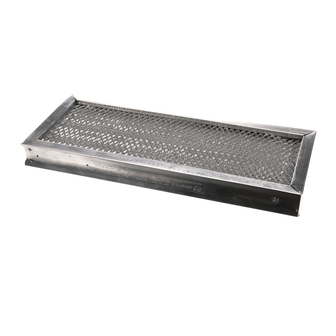
UV Lamps are numbered 1 to 6 from Front-to-Back • UV Ballasts are numbered 1 to 6 from Left-to-Right • The TOP of the UV Module has several long slots cut-out for ventilation GAYLORD GAYLORD DESCRIPTION DESCRIPTION PART NO. PART NO. -
Page 25: Gem System Diagram
GEM SYSTEM DIAGRAM... -
Page 26: Uv Hood Wiring
12512 D1,D2 Terminals for UV Access Door Switch #1 120VAC Indicator Light - Yellow 19162 G1,G2 Terminals for Gaylord Extractor Monitor (GEM) 120VAC Indicator Light - Red 12510 D3,D4 Terminals for UV Access Door Switch #2 120VAC UV Access Door Switch... -
Page 27: Wiring Diagrams
WIRING DIAGRAM FOR MODEL CUV-100 WITH GX2-UV-FDD AND GX2-UV-ND HOODS... -
Page 28: Wiring Diagrams
WIRING DIAGRAM FOR MODEL CUV-100 WITH GX2-UV-EDD STANDARD VENTILATOR... -
Page 29: Standard Ventilator Models
STANDARD VENTILATOR MODELS Model GX2-UV-FDD-BDL Model GX2-UV-FDD-BDL-CL Application - Wall mounted canopy Application - For single island style for all types of equipment. arrangements Model GX2-UV-FDD-BDL-DS Model GX2-UV-FDD-BDL-BB Application - For island style Application - For island style cooking arrangements where one side cooking arrangements over all duties of the cooking line is light duty equipment of equipment. -
Page 30: Metric Conversion Chart
METRIC CONVERSION CHART DIMENSIONS (Feet and Inches) WATER FLOW/VOLUME TO CONVERT MULTIPLY BY TO CONVERT MULTIPLY BY in ......mm ....25.4 U.S. ounce ....Liters ....02958 in ......cm ....2.54 U.S. gal ....Liters ....3.785 mm ......in ....0.03937 Liters ...... -
Page 31: Start-Up Inspection Report
PINK-Dealer GOLDENROD-Sales Rep Litho U.S.A. B. The exhaust fan came on ___Yes ___No GAYLORD INDUSTRIES 0900 S.W. Avery Street • Tualatin, OR 97062-1149 email:info@gaylordusa.com PHONE:1-503-691-2010 • FAX: 1-503-692-6048 • 2. Push “STOP FAN” button. A. The damper should move to the fully closed position in approx. 15 seconds_____Yes_____No B. -
Page 33: Warranty
THIS AGREEMENT. Service and Warranty Policies 1. No warranty work shall be performed on the product without a PO from Gaylord Industries, if financial reimbursement to be requested. 2. No warranty shall be provided on equipment that has been started up and in operation for more than 90 days unless, a product maintenance schedule has been created and performed per the requirements of this technical manual. - Page 34 CERTIFIED SERVICE AGENCY, VISIT OUR WEB SITE: WWW.GAYLORDUSA.COM OR CONTACT US AT: GAYLORD INDUSTRIES 10900 S.W. AVERY STREET TUALATIN, OREGON 97062-1149 U.S.A Phone: 503-691-2010 1-800-547-9696 Fax: 503-692-6048 email: info@gaylordusa.com LOCAL SERVICE AGENCY FORM NO. TM-GX2-UV-1204/____ © COPYRIGHT 2005, GAYLORD INDUSTRIES LITHO IN U.S.A.
Need help?
Do you have a question about the Ultima Vent GX2-UV and is the answer not in the manual?
Questions and answers