Table of Contents
Advertisement
Service
This manual is to be used by qualified appliance
technicians only. Maytag does not assume any
responsibility for property damage or personal
injury for improper service procedures done by
an unqualified person.
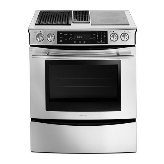
Electric
Slide-In
Range
This Base Manual covers general information
Refer to individual Technical Sheet
for information on specific models
This manual includes, but is
not limited to the following:
JES8750BA*
JES8850BA*
JES8850BC*
JES9750BA*
JES9800BA*
JES9860BA*
JES9860BC*
JES9900BA*
JES9900BC*
16026926
March 2006
©
2006 Maytag Services
Advertisement
Table of Contents

Related Manuals for Jenn-Air JES8750BA Series


Summary of Contents for Jenn-Air JES8750BA Series
- Page 1 Service This manual is to be used by qualified appliance technicians only. Maytag does not assume any This Base Manual covers general information responsibility for property damage or personal Refer to individual Technical Sheet injury for improper service procedures done by an unqualified person.
-
Page 2: Important Information
Important Information Maytag will not be responsible for personal injury or property damage from improper service procedures. Pride and workmanship go into every product to provide our customers with quality products. It is possible, however, that during its lifetime a product may require service. Products should be serviced only by a qualified service technician who is familiar with the safety procedures required in the repair and who is equipped with the proper tools, parts, testing instruments and the appropriate service information. -
Page 3: Table Of Contents
Table of Contents Important Information ........... 2 Disassembly Procedures Important Safety Information Removing and Replacing Range ......26 All Appliances ............4 Cartridge Assembly Removal (Select Models) ..26 Surface Cooking Units ..........4 Maintop Assembly Removal ........26 Ovens ............... 5 Control Panel Assembly Removal ...... -
Page 4: Important Safety Information
Important Safety Information ALL APPLIANCES WARNING 1. Proper Installation—Be sure your appliance is properly installed and grounded by a qualified To reduce the risk of the appliance tipping, it must be technician. secured by a properly installed anti-tip bracket(s). To make sure bracket has been installed properly, remove 2. -
Page 5: Ovens
Important Safety Information OVENS In Case of Fire 1. Use Care When Opening Door—Let hot air or steam Fires can occur as a result of over cooking or excessive escape before removing or replacing food. grease. Though a fire is unlikely, if one occurs, proceed as follows: 2. -
Page 6: Product Safety Devices
Important Safety Information Product Safety Devices Safety devices and features have been engineered into the product to protect consumer and servicer. Safety devices must never be removed, bypassed, or altered in such a manner as to defeat the purpose for which they were intended. -
Page 7: General Information
Brushed Chrome Amana Traditional White Magic Chef Traditional Almond Graffer & Prostyle Sattler Monochromatic Bisque Hardwick Stainless Jenn-Air Traditional Bisque Maytag W White on White Norge Frost White (True Color White) Universal Natural Bisque (True Color Bisque) Crosley Listing Fuel... -
Page 8: Specifications
Do Not Block Air Vents If registration card is missing: All air vents must be kept clear during cooking. If air • For Jenn-Air product call 1-800-536-6247 or visit the vents are covered during operation, the oven may Web Site at www.jennair.com overheat. -
Page 9: Range Description
Range Description Range Description Cooking Surface Downdraft Vent Infinite Switches Electronic Controls Oven Cavity: Broil Element Convection Element Bake Element Convection Fan Baking Racks Temperature Probe Access Panel: Model Number Rating Label 16026926 © 2006 Maytag Services... -
Page 10: Troubleshooting Procedures
Troubleshooting Procedures WARNING To avoid risk of electrical shock, personal injury, or death, disconnect power to range before servicing, unless testing requires power. Troubleshooting Chart Problem Possible Cause Correction Open bake element ........• Check element for continuity, replace if failed. -
Page 11: Description Of Fault Codes For Eoc Iii
Troubleshooting Procedures WARNING To avoid risk of electrical shock, personal injury, or death, disconnect power to range before servicing, unless testing requires power. Description of Fault Codes for EOC III Each fault code consists of 4 digits and is structured as follows: (Leftmost) Digit: Digit: Alpha-Character Digit: Secondary... -
Page 12: Oven Sensor, Meat Probe And Cooling Fan Temperature Charts
Troubleshooting Procedures WARNING To avoid risk of electrical shock, personal injury, or death, disconnect power to range before servicing, unless testing requires power. Oven Sensor, Meat Probe and Cooling Fan Temperature Charts OVEN SENSOR Sensor Type: RTD 1000 Ω platinum 1654 Ω... -
Page 13: Testing Procedures
Testing Procedures WARNING To avoid risk of electrical shock, personal injury, or death, disconnect power to range before servicing, unless testing requires power. Component Testing Procedures Illustration Component Test Procedure Results Oven light & housing Disconnect connector and test Verify bulb is properly inserted. resistance of terminals...... - Page 14 Testing Procedures WARNING To avoid risk of electrical shock, personal injury or death; disconnect power to range before servicing, unless testing requires power. Illustration Component Test Procedure Results Convection motor, Measure voltage ........120 VAC. (tolerance: 105 to 135 VAC). 2-speed Check motor windings to ground....
- Page 15 Testing Procedures WARNING To avoid risk of electrical shock, personal injury, or death, disconnect power to range before servicing, unless testing requires power. Illustration Component Test Procedure Results Ribbon element,100 W Disconnect wiring to element and measure cold resistance of terminals..Approx.
-
Page 16: Cooling Fan Temperatures
Testing Procedures WARNING To avoid risk of electrical shock, personal injury or death; disconnect power to range before servicing, unless testing requires power. Illustration Component Test Procedure Results Downdraft motor Measure voltage ........120 VAC. Check motor windings to ground....No continuity. -
Page 17: Control Testing Procedures
Testing Procedures WARNING To avoid risk of electrical shock, personal injury, or death, disconnect power to range before servicing, unless testing requires power. Control Testing Procedures Switch Membrane Assembly Test Procedure Results Closed circuitry resistance Trace Measurement 2 & 7 Continuity (defined as continuity): 2000 Max Ω... - Page 18 Testing Procedures WARNING To avoid risk of electrical shock, personal injury or death; disconnect power range before servicing, unless testing requires power. Switch Membrane Assembly Test Procedure Results Closed circuitry resistance Measurement Trace 2 & 7 Continuity (defined as continuity): 2000 Max Ω 2 &...
- Page 19 Testing Procedures WARNING To avoid risk of electrical shock, personal injury, or death, disconnect power to range before servicing, unless testing requires power. Switch Membrane Assembly Test Procedure Results Closed circuitry resistance Trace Measurement 2 & 7 Continuity (defined as continuity): 2000 Max Ω 2 &...
-
Page 20: Electronic Oven Control (Eoc Iii) Testing Procedures
Testing Procedures WARNING To avoid risk of electrical shock, personal injury or death; disconnect power range before servicing, unless testing requires power. Switch Membrane Assembly Test Procedure Results Closed circuitry resistance Measurement Trace 2 & 7 Continuity (defined as continuity): 2000 Max Ω 2 &... - Page 21 Testing Procedures WARNING To avoid risk of electrical shock, personal injury, or death, disconnect power to range before servicing, unless testing requires power. Feature Access Procedure Modification Procedure Press the Setup pad, then the left ATM pad Press the right ATM pad to scroll to the desired Time Options Determines control time, day of to select TIME OPTIONS.
- Page 22 Testing Procedures WARNING To avoid risk of electrical shock, personal injury or death; disconnect power to range before servicing, unless testing requires power. Feature Access Procedure Modification Procedure Press the Setup pad, then press the right ATM Press the left ATM pad to select 2 – 30, or 2 Timers Tones Determines the number and pad until TONES displays.
-
Page 23: Relay Logic For Eoc Iii
Testing Procedures WARNING To avoid risk of electrical shock, personal injury or death; disconnect power to range before servicing, unless testing requires power. Relay Logic for EOC III NOTE: Subsequent changes implemented after the release of this technical sheet may have altered the parameters identified in this chart. -
Page 24: Quick Test Mode For Eoc Iii
Testing Procedures WARNING To avoid risk of electrical shock, personal injury or death; disconnect power to range before servicing, unless testing requires power. "Quick Test" Mode for EOC III Follow the procedure below to perform the EOC III quick test. Once the control is in the quick test mode, any relay may be activated in any sequence. -
Page 25: Description Of Fault Codes For Eoc Iii
Testing Procedures WARNING To avoid risk of electrical shock, personal injury or death; disconnect power to range before servicing, unless testing requires power. Description of Fault Codes for EOC III Each fault code consists of 4 digits and is structured as follows: (Leftmost) Digit: Digit: Alpha-Character Digit: Secondary... -
Page 26: Disassembly Procedures
Disassembly Procedures To avoid risk of electrical shock, personal injury or death; disconnect power before servicing, unless testing requires power. 7. Label and disconnect wiring to elements (select Removing and Replacing Range models). 1. Remove power from unit. 8. Remove screws securing element mounting brackets 2. -
Page 27: Indicator Light Removal
Disassembly Procedures To avoid risk of electrical shock, personal injury or death; disconnect power before servicing, unless testing requires power. 4. Label and disconnect wire terminals from cooling fan. Indicator Light Removal 5. Remove screws securing fan to range chassis. 1. -
Page 28: Convection Motor Removal (Select Models)
Disassembly Procedures To avoid risk of electrical shock, personal injury or death; disconnect power before servicing, unless testing requires power. 6. Remove power to unit. Convection Motor Removal (Select Models) 7. Remove screw securing light socket to oven cavity. 1. Remove power from unit. 8. -
Page 29: Oven Door Latch Replacement
Disassembly Procedures To avoid risk of electrical shock, personal injury or death; disconnect power before servicing, unless testing requires power. Oven Door Removal Oven Door Latch Replacement 1. Remove control panel, see "Control Panel Removal" WARNING procedure. 2. Remove screws securing door latch to the front of the To avoid risk of personal injury or property damage, oven cavity outer shell. -
Page 30: Warming Drawer Disassembly (Select Models)
Disassembly Procedures To avoid risk of electrical shock, personal injury or death; disconnect power before servicing, unless testing requires power. Warming Drawer Disassembly Warming Drawer Track Disassembly (Select Models) (Select Models) 1. Remove warming door, see "Warming Drawer 1. Remove warming door, see "Warming Drawer Removal (Select Models)"... - Page 31 The Installation information provided in this service manual is representative of a limited number of models. Reference the customer’s Installation literature included with the product, order a copy (if needed), or consult Jenn-Air’s website for the specific model. www.jennair.com 16026926 A –...
-
Page 32: Appendix A: Installation Instructions
Installation Instructions Jenn-Air Electric Downdraft Range I N S T A L L A T I O N I N S T R U C T I O N S PLEASE KEEP THIS MANUAL FOR FUTURE REFERENCE This manual is intended to assist in the initial installation and adjustments of the range. - Page 33 Installation Instructions HOW TO REMOVE RANGE FOR SERVICING Follow these procedures to remove appliance for servicing: W A R N I N G 1. Slide range forward to disengage range from the anti-tip bracket. 2. Disconnect electrical supply to appliance, if equipped. 3.
- Page 34 Installation Instructions Dimensions/Dimensions/Dimensiones If cabinet backsplash behind unit is not present, kit UXA9107AA (B= black, S=stainless, W= white) may be ordered from dealer. S'il n'y a pas de dosseret derrière l'appareil, le nécessaire de finition UXA9107AA ” ( 7 6 (B = noir, S = acier inoxydable, W = blanc) peut .
- Page 35 Installation Instructions 5/16" 1/4" Included./Compris./Se incluye. Not Included./Non inclus./No se incluye. Tools Needed./Outils nécessaires./ Herramientas Necesarias. Vent Location Options/Options d’emplacement de l’évent/Opciones de ubicación de la ventilación Rear Wall Venting/Aération par la paroi Floor Venting/Aération par le sol/ Side Venting/Aération par le côté/ arrière/Ventilación de pared trasera Ventilación a través del piso Ventilación lateral...
- Page 36 Installation Instructions Rear Wall Venting/Aération par la paroi arrière/Ventilación de pared trasera 2 1/4” (7.94 cm) 8 3/16î (20.8 cm) Mark center of cabinet opening./Marquez le centre de l’ouverture de Mark and choose vent hole location. Check for obstructions (studs) in l’armoire./Marque el centro de la abertura del gabinete.
- Page 37 Installation Instructions Floor Venting/Aération par le sol/Ventilación a través del piso 8 3/8” 3 1/8” (21.27 cm) (7.93 cm) 6 3/8” (16.19 cm) 2 1/4”(5.71 cm) 9” (22.86 cm) 12 1/2” (31.75 cm) 18 3/4” (47.62 cm) 3 1/2” (8.89 cm) 1 1/2”...
- Page 38 Installation Instructions Left or Right Side Venting/Aération par le côté gauche ou droit/Ventilación por el costado izquierdo o derecho 31 3/16” (79.21 cm) 18” 5 1/2” (45.72 cm) (13.97 cm) Mark cabinet side for either left or right hole location. Check for obstructions in Cut one 5 1/2”...
- Page 39 Installation Instructions Left or Right Side Venting Aération par le côté gauche ou droit Ventilación por el costado izquierdo o derecho (suite) (cont.) (cont.) Rotate bracket 180 degrees and secure with (4) Go to other side of blower; remove bracket, rotate bracket 180 degrees locknuts./Faites tourner le support de 180 degrés et fixez-le avec (4) and secure with (4) locknuts./Rendez-vous de l’autre côté...
- Page 40 Installation Instructions Installation/Installation/Instalación Turn Off power source. Coupze I`alimentation. Apague el suminstro. Conduit Option/Option pour conduit/Opción del conducto Note: Strain relief for service cord or conduit MUST be attached to the conduit plate./Remarque: Le réducteur de tension du câble ou de la canalisation électrique DOIT être fixé...
- Page 41 Installation Instructions Option/Option/Opción Option/Option/Opción Position conduit plate as shown./ Slide conduit plate up and insert screws./Faites coulisser Positionnez la plaque à conduit la plaque du conduit vers le haut et remettez les vis./Deslice la comme il est illustré./Coloque la placa del placa del conducto hacia arriba y coloque los tornillos.
- Page 42 Installation Instructions G! US G! US VE TA VE TA R CO RD R CO RD RE MO RE MO PO WE PO WE IQ UE TA IQ UE TA WI TH WI TH NU TS NU TS LA ET LA ET CA S CA S...
- Page 43 Installation Instructions 4-Wire Connection/Raccordement - 4 fils/Conexión tetrafilar Part of copper ground strap MUST be cut out and removed./Une section Remove grounding screw, pull service cord through./Retirez la vis de de la bande en cuivre de mise à la terre DOIT être coupée et enlevée./ mise à...
- Page 44 Installation Instructions Bare 3-Wire Connection/Raccordement - 3 fils dénudés/Conexión trifilar descubierta Note: Conduit users should refer to special option steps a through g./Remarque: Si vous vous servez d’une canalisation, reportez-vous aux étapes spéciales a à g relatives à cette option./Nota: Si va a usar un conducto eléctrico, consulte los pasos de la opción especial a a la g. See NOTE./ See NOTE./ See NOTE/...
- Page 45 Installation Instructions Bare 4-Wire Connection/Raccordement - 4 fils dénudés/Conexión tetrafilar descubierta Note: Conduit users should refer to special option steps a through g./Remarque: Si vous vous servez d’une canalisation, reportez-vous aux étapes spéciales a à g relatives à cette option./Nota: Si va a usar un conducto eléctrico, consulte los pasos de la opción especial a a la g. Part of copper ground strap MUST be cut out and Attach lugs.
- Page 46 Installation Instructions Tighten Duct Clamp Serrez la pince du conduit Apriete la abrazadera del conducto Adjust legs. Note: Check counter top height (see dimensions) to allow Attach inlet ducting./Installez les conduits d’arrivée d’eau./ range top to clear countertop. Installer, take caution not to damage Instale los conductos de admisión.
- Page 47 Installation Instructions Tighten Duct Clamp Serrez la pince du conduit Apriete la abrazadera del conducto Adjust legs. Note: Check counter top height (see dimensions) to allow Attach inlet ducting./Installez les conduits d’arrivée d’eau./ range top to clear countertop. Installer, take caution not to damage Instale los conductos de admisión.
- Page 48 Installation Instructions Side venting/Aération par le côté/ Ventilación lateral Range Cuisinière Estufa BLOWER Flex Duct Tighten Duct Clamps Conduit flexible Serrez la pince du conduit Conducto flexible Apriete la abrazadera del conducto Make sure electrical cords are not kinked. Check leg position in ANTI-TIP Finish connecting duct work to range./Finissez de raccorder les bracket./Assurez-vous que les cordons électriques ne sont pas entortillés.
- Page 49 The Use and Care information provided in this service manual is representative of a limited number of models. Reference the customer’s Use and Care literature included with the product, order a copy (if needed), or consult Jenn-Air’s website for the specific model. www.jennair.com 16026926 B –...
- Page 50 Use & Care Information B – 2 16026926 © 2006 Maytag Services...
- Page 51 Use & Care Information 16026926 B – 3 © 2006 Maytag Services...
- Page 52 Use & Care Information B – 4 16026926 © 2006 Maytag Services...
- Page 53 Use & Care Information 16026926 B – 5 © 2006 Maytag Services...
- Page 54 Use & Care Information B – 6 16026926 © 2006 Maytag Services...
- Page 55 Use & Care Information 16026926 B – 7 © 2006 Maytag Services...
- Page 56 Use & Care Information B – 8 16026926 © 2006 Maytag Services...
- Page 57 Use & Care Information 16026926 B – 9 © 2006 Maytag Services...
- Page 58 Use & Care Information B – 10 16026926 © 2006 Maytag Services...
- Page 59 Use & Care Information 16026926 B – 11 © 2006 Maytag Services...
- Page 60 Use & Care Information B – 12 16026926 © 2006 Maytag Services...
- Page 61 Use & Care Information 16026926 B – 13 © 2006 Maytag Services...
- Page 62 Use & Care Information B – 14 16026926 © 2006 Maytag Services...
- Page 63 Use & Care Information 16026926 B – 15 © 2006 Maytag Services...
- Page 64 Use & Care Information B – 16 16026926 © 2006 Maytag Services...
- Page 65 Use & Care Information 16026926 B – 17 © 2006 Maytag Services...
- Page 66 Use & Care Information B – 18 16026926 © 2006 Maytag Services...
- Page 67 Use & Care Information 16026926 B – 19 © 2006 Maytag Services...