Table of Contents

Subscribe to Our Youtube Channel
Related Manuals for IEI Technology AFL-xxx-9103


Summary of Contents for IEI Technology AFL-xxx-9103
- Page 1 AFL-xxx-9103 Panel PC MODEL: AFL-xxx-9103 Panel PC with Touch Screen and Intel® Celeron® CPU Gigabit Ethernet, Four USB, Audio, RS-232/422/485, SATA RoHS Compliant, IP 64 Protection User Manual Page i Rev. 1.00 September, 2008...
- Page 2 AFL-xxx-9103 Panel PC Revision Date Version Changes September, 2008 1.00 Initial release Page ii...
- Page 3 AFL-xxx-9103 Panel PC Copyright COPYRIGHT NOTICE The information in this document is subject to change without prior notice in order to improve reliability, design and function and does not represent a commitment on the part of the manufacturer. In no event will the manufacturer be liable for direct, indirect, special, incidental, or consequential damages arising out of the use or inability to use the product or documentation, even if advised of the possibility of such damages.
- Page 4 Cautionary messages should also be heeded to help reduce the chance of losing data or damaging the AFL-xxx-9103. Cautions are easy to recognize. The word “caution” is written as “CAUTION,” both capitalized and bold and is followed. The text is the cautionary message.
- Page 5 “NOTE,” both capitalized and bold and is followed by text. The text is the cautionary message. A note message is shown below: NOTE: This is an example of a note message. Notes should always be read. Notes contain critical information about the AFL-xxx-9103. Please take note messages seriously. Page v...
-
Page 6: Packing List
AFL-xxx-9103 from or contact an IEI sales representative directly. To contact an IEI sales representative, please send an email to sales@iei.com.tw. The items listed below should all be included in the AFL-xxx-9103 package. 1 x AFL-xxx-9103 1 x Screw kit... -
Page 7: Table Of Contents
AFL-xxx-9103 Panel PC Table of Contents 1 INTRODUCTION......................1 1.1 O ......................... 2 VERVIEW 1.1.1 Model Variations ....................3 1.1.2 Applications ....................... 3 1.1.3 Standard Features ....................4 1.2 E ....................4 XTERNAL VERVIEW 1.2.1 Front Panel ......................5 1.2.2 Rear Panel ......................6 1.2.3 Bottom Panel...................... - Page 8 AFL-xxx-9103 Panel PC 2.4 G ....................20 IGABIT THERNET 2.5 M ........................21 EMORY 2.6 S ........................21 TORAGE ® 2.6.1 CompactFlash ....................21 2.6.2 Hard Drive ....................... 22 2.7 B ....................23 LUETOOTH ODULE 2.8 HSDPA M )................. 24...
- Page 9 AFL-xxx-9103 Panel PC 3.1 I ................... 42 NSTALLATION RECAUTIONS 3.2 P .................. 42 REINSTALLED OMPONENTS 3.3 I ............. 43 NSTALLATION AND ONFIGURATION TEPS 3.4 U ......................43 NPACKING 3.4.1 Packing List ..................... 44 3.4.2 Optional Items....................45 ® 3.5 C ..............
- Page 10 AFL-xxx-9103 Panel PC 4.5.6.3 COM3 Pin-12 Signal Setting ..............73 4.5.6.4 COM3 Pin-8 Signal Setting ..............73 4.5.6.5 COM3 Long Distance RS-422/485............74 4.5.7 LCD Voltage Selection ..................74 4.5.8 Panel Resolution ....................75 4.5.9 Touch Panel Type ..................... 75 5 BIOS SETUP ........................
- Page 11 AFL-xxx-9103 Panel PC 5.9 E ........................116 6 DRIVER INSTALLATION..................118 6.1 A ................119 VAILABLE OFTWARE RIVERS 6.2 D CD A ...................119 RIVER 6.3 C ....................120 HIPSET RIVER 6.4 G ....................124 RAPHICS RIVER 6.5 G .................. 128 IGABIT THERNET RIVER 6.6 A...
- Page 12 AFL-xxx-9103 Panel PC G HAZARDOUS MATERIALS DISCLOSURE ............173 G.1 H IPB P AZARDOUS ATERIALS ISCLOSURE ABLE FOR RODUCTS ERTIFIED AS HS C 2002/95/EC W ........174 OMPLIANT NDER ITHOUT ERCURY H AC'97 AUDIO CODEC .................... 177 H.1 I ..................... 178 NTRODUCTION H.1.1 Accessing the AC’97 CODEC ...............
- Page 13 Figure 3-3: CompactFlash® Card Slot Location................47 Figure 3-4: AFL-12B-9103-R10 Cover Retention Screws............48 Figure 3-5: AFL-12B-9103-R10 Bracket Retention Screws............48 Figure 3-6: AFL-xxx-9103 Hard Drive Retention Screws ............49 Figure 3-7: AT/ATX Switch Location...................50 Figure 3-8: Wall-mounting Bracket .....................52 Figure 3-9: Chassis Support Screws ..................53 Figure 3-10: Secure the Panel PC ....................54...
- Page 14 AFL-xxx-9103 Panel PC Figure 3-15: The Rack/Cabinet Bracket..................59 Figure 3-16: Secure the Rack/Cabinet Bracket................59 Figure 3-17: Install into a Rack/Cabinet ..................60 Figure 3-18: LAN Connection ......................61 Figure 3-19: Serial Device Connector..................62 Figure 3-20: USB Device Connection ..................63 Figure 4-1: AFL-10A-9103-R10 Aluminum Back Cover Retention Screws ......66 Figure 4-2: AFL-12B-9103-R10 Aluminum Back Cover Retention Screws ......67...
- Page 15 AFL-xxx-9103 Panel PC Figure 6-25: Windows Logo Testing..................135 Figure 6-26: Create Shortcut Wizard ..................136 Figure 6-27: Software Driver Folder..................137 Figure 6-28: Wireless LAN Setup Language................137 Figure 6-29: Installation Welcome Screen ................138 Figure 6-30: Wireless LAN Driver License Agreement ............138 Figure 6-31: Wireless LAN Setup Options ................
- Page 16 AFL-xxx-9103 Panel PC List of Tables Table 1-1: Model Variations ......................3 Table 1-2: System Specifications....................10 Table 1-3: Motherboard Specifications ..................11 Table 1-4: AFL-10A-9103-R10 TFT LCD Monitor Specifications ..........11 Table 1-5: AFL-12B-9103-R10 TFT LCD Monitor Specifications ..........12 Table 1-6: Touch Panel Specifications ..................13 Table 1-7: Bluetooth Module Specifications................13...
- Page 17 AFL-xxx-9103 Panel PC Table 3-2: Optional Items......................45 Table 4-1: AT/ATX Power Selection ....................71 Table 4-2: AT/ATX Power Selection ....................71 Table 4-3: Clear CMOS .........................71 Table 4-4: CompactFlash® Master/Slave Selection ..............71 Table 4-5: COM1 Pin-9 Setting ....................72 Table 4-6: COM2 Pin-9 Setting ....................72 Table 4-7: COM3 Pin-9 Setting ....................73...
- Page 18 AFL-xxx-9103 Panel PC BIOS Menus BIOS Menu 1: Main ........................79 BIOS Menu 2: Advanced ......................81 BIOS Menu 3: CPU Configuration ....................82 BIOS Menu 4: IDE Configuration....................83 BIOS Menu 5: IDE Master and IDE Slave Configuration ............84 BIOS Menu 6: Super IO Configuration..................89 BIOS Menu 7: Hardware Health Configuration ................92...
-
Page 19: Introduction
AFL-xxx-9103 Panel PC Chapter Introduction Page 1... -
Page 20: Overview
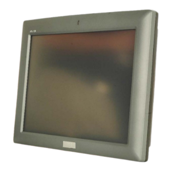
1.1 Overview Figure 1-1: AFL-xxx-9103 The AFL-xxx-9103 is a fanless flat panel PC for in-car entertainment or logistics, digital surveillance, self-service kiosks, ATMs, general ticketing machines and home automation. The touch screen interface allows the AFL-xxx-9103 to be operated without a keyboard or mouse by simply pressing on the screen. -
Page 21: Model Variations
12.1” Celeron Table 1-1: Model Variations 1.1.2 Applications The AFL-xxx-9103 all-in-one panel PC is designed for multiple applications. Its durability and strength makes it an ideal choice for public access computers. Some possible applications include: Vehicle Interior device Truck PC... -
Page 22: Standard Features
RoHS compliance 1.2 External Overview The AFL-xxx-9103 is a stylish flat panel PC that comprises of a screen, rear panel, and bottom panel. An ABS/PC plastic front frame surrounds the front screen. The rear panel provides screw holes for a wall-mounting bracket compliant with VESA FDMI standard. -
Page 23: Front Panel
AFL-xxx-9103 Panel PC 1.2.1 Front Panel The front side of the AFL-xxx-9103 is a flat panel TFT LCD screen surrounded by an ABS/PC plastic frame. Figure 1-2: Front View Page 5... -
Page 24: Rear Panel
The rear panel provides access to retention screw holes that support the wall mounting. Refer to Figure 1-3. Figure 1-3: Rear View 1.2.3 Bottom Panel The bottom panel of the AFL-xxx-9103 has the following I/O interfaces (Figure 1-4): 1 x Audio out 4 x USB 2.0 connectors 1 x Power connector... -
Page 25: Internal Overview
Figure 1-4: Bottom View 1.3 Internal Overview The AFL-xxx-9103 internal components are protected in an aluminum chassis inside the plastic back cover. An AT/ATX switch is located on the side of the aluminum chassis inside the plastic cover. The motherboard, wireless LAN module, Bluetooth module and DDR2 memory module are installed on a metal sheet that protects the rear of the TFT LCD screen (Figure 1-5). -
Page 26: Specifications
AFL-xxx-9103 Panel PC Figure 1-5: AFL-xxx-9103 Internal Overview 1.4 Specifications 1.4.1 Preinstalled Hardware Components The AFL-xxx-9103 flat panel PC has the following preinstalled components: 1 x Motherboard 1 x TFT LCD screen 1 x Touch screen 1 x Inverter 1 x Wireless LAN module... -
Page 27: System Specifications
1 x HSDPA module (optional) The technical specifications for some of these components and the system are shown in the sections below. 1.4.2 System Specifications The technical specifications for the AFL-xxx-9103 are listed in Table 1-2. SPECIFICATION AFL-10A-9103-R10 AFL-12B-9103-R10 Front Panel... -
Page 28: Motherboard Specifications
Safety & EMI CE / FCC / CCC / UL / CB Table 1-2: System Specifications 1.4.3 Motherboard Specifications The AFL-xxx-9103 series come with an AFLMB-9103GME motherboard. The technical specifications of the motherboard are listed in Table 1-3. Specification AFLMB-9103GME Intel®... -
Page 29: Flat Panel Screen Specifications
Table 1-3: Motherboard Specifications 1.4.4 Flat Panel Screen Specifications The AFL-xxx-9103 series come with a TFT LCD monitor at the front of the flat panel PC (see Figure 1-2). The specifications for the LCD monitor are shown below. 1.4.4.1 AFL-10A-9103-R10... -
Page 30: Touch Screen Specifications
50000 Dimensions (WxHxD)(mm) 278.3 x 209.0 x 12.0 Table 1-5: AFL-12B-9103-R10 TFT LCD Monitor Specifications 1.4.5 Touch Screen Specifications The AFL-xxx-9103 series come with an analog resistive type touch panel. Table 1-6 lists the touch panel specifications. SPECIFICATION AFL-10A-9103-R10 AFL-12B-9103-R10... -
Page 31: Bluetooth Module Specifications
204 x 268 x 2.1 Table 1-6: Touch Panel Specifications 1.4.6 Bluetooth Module Specifications The AFL-xxx-9103 series are all integrated with a Bluetooth module. The Bluetooth module enables the transmission between various peripheral devices through a Bluetooth network. The peripheral devices may include:... -
Page 32: Optional Hsdpa Module Specifications
AFL-xxx-9103 Panel PC 1.4.7 Optional HSDPA Module Specifications The HSDPA module is one of the OEM options for the AFL-xxx-9103. The technical specifications of the HSDPA module are listed in Table 1-8. Specification HSDPA Module EDG/HSDPA/GSM Air Interface Quad-band operation GSM850, EGSM 900, DCS 1800, PCS... -
Page 33: Afl-10A-9103-R10 Dimensions
AFL-xxx-9103 Panel PC 1.5.1 AFL-10A-9103-R10 Dimensions The dimensions of the AFL-10A-9103-R10 are shown in Figure 1-6 below. Figure 1-6: AFL-10A-9103-R10 Dimensions (units in mm) Page 15... -
Page 34: Afl-12B-9103-R10 Dimensions
AFL-xxx-9103 Panel PC 1.5.2 AFL-12B-9103-R10 Dimensions The dimensions of the AFL-12B-9103-R10 are shown in Figure 1-7 below. Figure 1-7: AFL-12B-9103-R10 Dimensions (units in mm) Page 16... -
Page 35: Motherboard
AFL-xxx-9103 Panel PC Chapter Motherboard Page 17... -
Page 36: Introduction
This chapter gives a brief introduction to the AFLMB-9103GME motherboard. 2.2 CPU Support The AFL-xxx-9103 motherboard comes with a preinstalled Intel® Celeron CPU. The specifications for the Intel® Celeron CPU are listed below 5.5 watts power consumption... -
Page 37: Graphics Support
AFL-xxx-9103 Panel PC Complies with PCI Local Bus Specification, Revision 2.3 and supports 33 MHz PCI operations Supports ACPI Power Management Logic Contains: Enhanced DMA controller Interrupt controller Timer functions Integrated SATA host controller with DMA operations interfaced to two SATA... -
Page 38: Gigabit Ethernet
AFL-xxx-9103 Panel PC 2.4 Gigabit Ethernet A highly integrated and cost-effective single-chip, fast Realtek RTL8111CP GbE controller is interfaced through first the PCI bus to the CPU and system chipset. Figure 2-1: Gigabit Ethernet The Realtek RTL8111CP controller provides 10 Mb/s, 100 Mb/s or 1000 Mb/s Ethernet connectivity to the AFLMB-9103GME. -
Page 39: Memory
AFL-xxx-9103 Panel PC 2.5 Memory The Intel® 910GMLE in the AFL-xxx-9103 contains an internal DDR2 controller. The DDR2 controller has the following features: Low-latency, high-bandwidth 400 MHz 128-bit DDR2 SDRAM controller Supports one un-buffered DDR2 SO-DIMM Each SO-DIMM has a maximum capacity of 2.0 GB The DDR2 controller on the Northbridge is interfaced to one SO-DIMM socket on the AFL-xxx-9103. -
Page 40: Hard Drive
Figure 2-3: CompactFlash® Slot 2.6.2 Hard Drive The AFL-xxx-9103 supports a single SATA or IDE hard drive. This hard drive is installed internally and connected to the SATA port or IDE connector on the AFLMB-9103GME motherboard. A second SATA connector is implemented externally through an eSATA connector. -
Page 41: Bluetooth Module
AFL-xxx-9103 Panel PC Figure 2-5: External SATA Hard Drive 2.7 Bluetooth Module The AFL-xxx-9103 are all integrated with a Bluetooth module. The Bluetooth module enables the transmission between various peripheral devices through a Bluetooth network. Figure 2-6: Bluetooth Module Bluetooth enabled peripheral devices include:... -
Page 42: Hsdpa Module (Optional)
Figure 2-7: HSDPA Module The HSDPA module connects to 3G and 3.5G cellular networks. The connectivity provided by the HSDPA module allows the AFL-xxx-9103 to connect through the Internet to remote networks, allowing the AFL-xxx-9103 to send and receive from wherever there is cellular coverage. -
Page 43: Wireless Lan
PCIe Mini interface VIA® Solomon VT6656 wireless LAN controller 2.10 Front Panel The front panel of the AFL-xxx-9103 consists of an LCD monitor and a touch screen panel. 2.10.1 LCD Screen The AFL-xxx-9103 comes with a TFT LCD monitor. The tough construction of the TFT monitor allows the AFL-xxx-9103 to withstand the conditions it is likely to be exposed to during regular use. -
Page 44: Touch Screen
C operating temperature 2.10.2 Touch Screen The touch screen panel on the AFL-xxx-9103 allows complete user interaction without the need for a keyboard or mouse. Some of the features of the touch panel are listed below. 5-wire analog resistive type... -
Page 45: Touch Screen Connector
AFL-xxx-9103 Panel PC Figure 2-9: AFLMB-9103GME Connector Overview 2.11.1 Touch Screen Connector CN Label: PANEL CN Type: 9-pin connector CN Location: See Figure 2-9 CN Pinouts: See Table 2-1 The touch screen connector connects to the touch screen on the front panel of the AFL-xxx-9103. -
Page 46: Gpio Connector
CN Pinouts: See Table 2-2 The GPIO connector is connected to external devices and can be programmed for external machine control. As standard, the GPIO connector is not used in the AFL-xxx-9103, but is still functional. DESCRIPTION DESCRIPTION VCC5 GPO0... -
Page 47: Keypad Connector
AFL-xxx-9103 Panel PC DESCRIPTION DESCRIPTION POWER_LED_G HDD_POWER HDD_LED- POWER_LED_O PS_ON Table 2-3: Front Panel Connectors 2.11.4 Keypad Connector CN Label: JP16 CN Type: 10-pin connector CN Location: See Figure 2-9 CN Pinouts: See Table 2-4 The keypad connector connects to a numeric keypad for access control systems. -
Page 48: Backlight Connector
AFL-xxx-9103 Panel PC DESCRIPTION DESCRIPTION WAKE# VCC3 RESERVED RESERVED VCC1.5 CLKREQ# REFCLK- REFCLK+ PERST# PERn0 VCC3_AUX PERp0 VCC1.5 SMB_CLK PETn0 SMB_DATA PETp0 USB_DATA- RESERVED USB_DATA+ RESERVED RESERVED LED_WWAN# RESERVED LED_WLAN# RESERVED LED_WPAN# RESERVED VCC1.5 RESERVED RESERVED VCC3 Table 2-5: Front Panel Connectors 2.11.6 Backlight Connector... -
Page 49: Vga Connector
AFL-xxx-9103 Panel PC CN Location: See Figure 2-9 CN Pinouts: See Table 2-6 The backlight connector provides power for the LCD panel backlight. DESCRIPTION INV VCC INV VCC LCDBKTCT Brightness Table 2-6: Backlight Connector 2.11.7 VGA Connector CN Label: 10-pin box header... -
Page 50: Hard Drive Power Connector
CN Pinouts: See Table 2-8 The hard drive power connector provides power to an hard drive installed in the AFL-xxx-9103. The hard drive power connector is specifically intended to be used with an installed SATA hard drive. DESCRIPTION +5 V... -
Page 51: Audio Output Connector
AFL-xxx-9103 Panel PC DESCRIPTION DESCRIPTION DATA 7 DATA 15 HDC_CS1# HDC_CS3# GROUND IOR# IOW# VCC5 IRQ15 VCC_COM VCC5 CSEL HDD_RESET IORDY PDREQ PDACK# DATA 0 66DET DATA 1 DATA 8 DATA 2 DATA 9 DATA 10 VCC-IN CHECK2 GROUND Table 2-9: CompactFlash® Connector 2.11.10 Audio Output Connector... -
Page 52: Microphone Input Connector
AFL-xxx-9103 Panel PC DESCRIPTION Line-out-L Line-out-R Table 2-10: Audio Output Connector 2.11.11 Microphone Input Connector CN Label: MIC1 CN Type: 2-pin connector CN Location: See Figure 2-9 CN Pinouts: See Table 2-11 The microphone input connector connects to a microphone for audio input. -
Page 53: Com3 Rs-232/422/485 Serial Port Connector
AFL-xxx-9103 Panel PC DESCRIPTION Table 2-12: 12 V Power Connector 2.11.13 COM3 RS-232/422/485 Serial Port Connector CN Label: COM3 CN Type: DB-9 male CN Location: See Figure 2-9 CN Pinouts: See Table 2-13 The COM3 serial port connector provides an RS-232, RS-422 or RS-485 data connection to an attached device. -
Page 54: Sata Ports
AFL-xxx-9103 Panel PC The COM1 serial port connector provides an RS-232 data connection to attached devices. DESCRIPTION DCD1 DTR1 DSR1 RTS1 CTS1 Table 2-14: COM1 Serial Port Connector 2.11.15 SATA Ports CN Label: SATA1 CN Type: SATA connector CN Location:... -
Page 55: Sata Ports
AFL-xxx-9103 Panel PC DESCRIPTION Table 2-15: SATA1 Connector 2.11.16 SATA Ports CN Label: SATA2 SATA connector CN Type: CN Location: See Figure 2-9 CN Pinouts: See Table 2-16 The SATA connectors connect to SATA hard drives and SATA CD-ROMs. DESCRIPTION Table 2-16: SATA Connector 2.11.17 PS/2 Keyboard &... -
Page 56: Battery Connector
AFL-xxx-9103 Panel PC The PS/2 connector connects to a PS/2 keyboard and mouse. DESCRIPTION VCC5 MOUSE DATA MOUSE CLK KEYBOARD DATA KEYBOARD CLK Table 2-17: PS/2 Keyboard & Mouse Connector 2.11.18 Battery Connector CN Label: 4-pin box header CN Type:... -
Page 57: Lvds Connector
AFL-xxx-9103 Panel PC CN Pinouts: See Table 2-19 The fan connects to a system fan. The system fan provides cooling for the computer. The fan speed is read by the computer and then adjusted according to temperature and fan settings. -
Page 58: Usb Connectors (Internal)
AFL-xxx-9103 Panel PC DESCRIPTION DESCRIPTION LVDS3+ LVDS3- VCCLCD VCCLCD VCCLCD VCCLCD Table 2-20: LVDS Connector 2.11.21 USB Connectors (Internal) CN Label: USB3 CN Type: 8-pin header CN Location: See Figure 2-9 CN Pinouts: See Table 2-21 The USB connectors connect to USB devices. -
Page 59: Installation
AFL-xxx-9103 Panel PC Chapter Installation Page 41... -
Page 60: Installation Precautions
AFL-xxx-9103 Panel PC 3.1 Installation Precautions When installing the flat panel PC, please follow the precautions listed below: Power turned off: When installing the flat panel PC, make sure the power is off. Failing to turn off the power may cause severe injury to the body and/or damage to the system. -
Page 61: Installation And Configuration Steps
AFL-xxx-9103 Panel PC 3.3 Installation and Configuration Steps The following installation steps must be followed. Step 1: Unpack the flat panel PC Step 2: Install CompactFlash® card Step 3: Install HDD Step 4: Mount the flat panel PC Step 5:... -
Page 62: Packing List
Step 7: Open the small box inside and make sure all the components listed in the packing list are present. Step 0: 3.4.1 Packing List The AFL-xxx-9103 is shipped with the following components: Quantity Item Image AFL-xxx-9103 60 W power adapter... -
Page 63: Optional Items
If any of these items are missing or damaged, contact the distributor or sales representative immediately. ® 3.5 CompactFlash Card Installation The AFL-xxx-9103 has one CompactFlash® slot inside the rear panel. To install the CompactFlash® card, follow the instructions below. Page 45... -
Page 64: Figure 3-1: Afl-10A-9103-R10 Cover Retention Screws
AFL-xxx-9103 Panel PC Step 1: Remove the retention screws (Figure 3-1 and Figure 3-2) and lift the plastic cover off the flat panel PC. Figure 3-1: AFL-10A-9103-R10 Cover Retention Screws Figure 3-2: AFL-12B-9103-R10 Back Cover Retention Screws Step 2: Locate the CompactFlash® card slot. Insert a CompactFlash® card into the slot (Figure 3-3). -
Page 65: Hard Drive Installation
AFL-xxx-9103 Panel PC Figure 3-3: CompactFlash® Card Slot Location Step 3: Replace the plastic back cover. Once replaced, fasten the previously removed retention screws. Step 0: 3.6 Hard Drive Installation The AFL-12B-9103-R10 has space for a hard drive. To install the hard drive, please follow... -
Page 66: Figure 3-4: Afl-12B-9103-R10 Cover Retention Screws
AFL-xxx-9103 Panel PC Figure 3-4: AFL-12B-9103-R10 Cover Retention Screws Step 3: Remove the four hard drive bracket retention screws (Figure 3-5) and lift the hard drive bracket off the panel PC. Figure 3-5: AFL-12B-9103-R10 Bracket Retention Screws Page 48... -
Page 67: At/Atx Mode Selection
Step 0: 3.7 AT/ATX Mode Selection AT and ATX power modes can both be used on the AFL-xxx-9103. The selection is made through an AT/ATX switch on the aluminum chassis inside the plastic back cover (Figure 3-7). To select AT mode or ATX mode, follow the steps below. -
Page 68: At Power Mode
Manufacturing shop flow 3.7.2 ATX Power Mode With the ATX mode selected, the AFL-xxx-9103 goes in a standby mode when it is turned off. The panel PC can be easily turned on via network or a power switch in standby mode. -
Page 69: Mounting The System
PC does not fall down and get damaged. The four methods of mounting the AFL-xxx-9103 are listed below. Wall mounting Stand/Arm mounting The four mounting methods are described below. -
Page 70: Figure 3-8: Wall-Mounting Bracket
AFL-xxx-9103 Panel PC Step 5: Secure the mounting-bracket to the wall by inserting the retention screws into the four pilot holes and tightening them (Figure 3-8). Figure 3-8: Wall-mounting Bracket Step 6: Insert the four monitor mounting screws provided in the wall mounting kit into the four screw holes on the real panel of the flat panel PC and tighten until the screw shank is secured against the rear panel (Figure 3-9). -
Page 71: Figure 3-9: Chassis Support Screws
AFL-xxx-9103 Panel PC Figure 3-9: Chassis Support Screws NOTE: In the diagram below the bracket is already installed on the wall. Step 9: Secure the panel PC by fastening the retention screw of the wall-mounting bracket. (Figure 3-10).Step 0: Page 53... -
Page 72: Arm Mounting
3.8.2 Arm Mounting The AFL-xxx-9103 is VESA (Video Electronics Standards Association) compliant and can be mounted on an arm with a VESA compliant interface pad. To mount the AFL-xxx-9103 series on an arm, please follow the steps below. Step 1: The arm is a separately purchased item. -
Page 73: Figure 3-11: Arm Mounting Screw Holes
PC onto the interface pad of the mounting arm. Step 3: Align the retention screw holes on the mounting arm interface with those in the flat panel PC. The AFL-xxx-9103 arm mount retention screw holes are shown in Figure 3-11. Figure 3-11: Arm Mounting Screw Holes... -
Page 74: Panel Mounting
AFL-xxx-9103 Panel PC 3.8.3 Panel Mounting To mount the AFL-xxx-9103 into a panel, please follow the steps below. Step 1: Select the position on the panel to mount the flat panel PC. Step 2: Cut out a section from the panel that corresponds to the rear panel dimensions of the flat panel PC. -
Page 75: Figure 3-13: Afl-12B-9103-R10 Panel Opening
AFL-xxx-9103 Panel PC Figure 3-13: AFL-12B-9103-R10 Panel Opening Step 3: Slide the flat panel PC through the hole until the aluminum frame is flush against the panel. Step 4: Insert the panel mounting clamps into the pre-formed holes along the edges of the chassis, behind the aluminum frame. -
Page 76: Cabinet And Rack Installation
Figure 3-14: Tighten the Panel Mounting Clamp Screws 3.8.4 Cabinet and Rack Installation The AFL-xxx-9103 can be installed into a cabinet or rack. The installation procedures are similar to the panel mounting installation. To do this, please follow the steps below:... -
Page 77: Figure 3-15: The Rack/Cabinet Bracket
Insert the rack mounting clamps into the pre-formed holes along the edges of the flat panel PC, behind the ABS/PC plastic frame. There are a total of 6 rack mounting clamps for the AFL-xxx-9103. Step 3: Tighten the screws that pass through the rack mounting clamps until the plastic caps at the front of all the screws are firmly secured to the bracket (Figure 3-16). -
Page 78: Bottom Panel Connectors
To connect a LAN cable with an RJ-45 connector, please follow the instructions below. Step 1: Locate the RJ-45 connectors on the bottom panel of the AFL-xxx-9103 Series. Step 2: Align the connectors. Align the RJ-45 connector on the LAN cable with one of the RJ-45 connectors on the bottom panel of the AFL-xxx-9103. -
Page 79: Serial Device Connection
RJ-45 connector into the onboard RJ-45 connector. Step 0: 3.9.2 Serial Device Connection The AFL-xxx-9103 has two single female DB-9 connectors on the bottom panel for a serial device. Follow the steps below to connect a serial device to the AFL-xxx-9103 Series panel PC. -
Page 80: Usb Device Connection
Step 0: 3.9.3 USB Device Connection There are four external USB 2.0 connectors. All connectors are perpendicular to the AFL-xxx-9103. To connect a USB 2.0 or USB 1.1 device, please follow the instructions below. Step 1: Located the USB connectors. The locations of the USB connectors are shown in Chapter 2. -
Page 81: Figure 3-20: Usb Device Connection
AFL-xxx-9103 Panel PC Figure 3-20: USB Device Connection Step 3: Insert the device connector. Once aligned, gently insert the USB device connector into the onboard connector. Step 0: Page 63... -
Page 82: System Maintenance
AFL-xxx-9103 Panel PC Chapter System Maintenance Page 64... -
Page 83: System Maintenance Introduction
AFL-xxx-9103 Panel PC 4.1 System Maintenance Introduction If the components of the AFL-xxx-9103 fail they must be replaced, such as the wireless LAN module or the motherboard. Please contact the system reseller or vendor to purchase the replacement parts. Back cover removal instructions and jumper settings for the AFL-xxx-9103 are described below. -
Page 84: Figure 4-1: Afl-10A-9103-R10 Aluminum Back Cover Retention Screws
Bluetooth module HSDPA module Inverter The internal aluminum back cover of the AFL-xxx-9103 series must be removed. To remove the aluminum back cover, please follow the steps below. Step 1: Remove the retention screws securing the internal aluminum cover (Figure 4-1 and Figure 4-2). -
Page 85: Memory Module Replacement
AFL-xxx-9103 Panel PC Figure 4-2: AFL-12B-9103-R10 Aluminum Back Cover Retention Screws Step 2: Lift the aluminum cover off the AFL-xxx-9103. The AT/ATX switch on the aluminum cover is connected to the motherboard. Be careful when lifting the cover off. Step 0: 4.4 Memory Module Replacement... -
Page 86: Figure 4-3: So-Dimm Socket Location
AFL-xxx-9103 Panel PC Figure 4-3: SO-DIMM Socket Location Step 4: Remove the thermal pad off the memory module. Step 5: Remove the DDR2 memory module by pulling both the spring retainer clips outward from the socket. Step 6: Grasp the DDR2 memory module by the edges and carefully pull it out of the socket. -
Page 87: Jumper Settings
AFL-xxx-9103 Panel PC Figure 4-4: DDR2 SO-DIMM Module Installation Step 10: Re-attach the thermal pad into the memory module. Step 0: 4.5 Jumper Settings NOTE: A jumper is a metal bridge that is used to close an electrical circuit. It... -
Page 88: Figure 4-5: Jumper Locations
AFL-xxx-9103 Panel PC 4.5.5 COM2 Pin-9 Setting ..............72 4.5.6 COM3 Settings................72 4.5.6.1 COM3 Pin-9 Setting ..............73 4.5.6.2 COM3 RS-422/485 Select ............73 4.5.6.3 COM3 Pin-12 Signal Setting ............73 4.5.6.4 COM3 Pin-8 Signal Setting ............73 4.5.6.5 COM3 Long Distance RS-422/485 ..........74 4.5.7 LCD Voltage Selection .............. -
Page 89: At/Atx Power Selection
AFL-xxx-9103 Panel PC 4.5.1 AT/ATX Power Selection This jumper sets the power as using AT power or ATX power. JP10 Description 1-2 closed AT power 1-2 open ATX power Table 4-1: AT/ATX Power Selection JP12 Description 1-2 closed 1-2 open Table 4-2: AT/ATX Power Selection 4.5.2 Clear CMOS... -
Page 90: Com1 Pin-9 Setting
AFL-xxx-9103 Panel PC 4.5.4 COM1 Pin-9 Setting Pin 9 on serial port COM1 can be set to provide 5 V or 12 V of power, or as the ring indicator. Description 12 V Table 4-5: COM1 Pin-9 Setting 4.5.5 COM2 Pin-9 Setting Pin 9 on serial port COM2 can be set to provide 5 V or 12 V of power, or as the ring indicator. -
Page 91: Com3 Pin-9 Setting
AFL-xxx-9103 Panel PC 4.5.6.1 COM3 Pin-9 Setting Pin 9 on serial port COM3 can be set to provide 5 V or 12 V of power, or as the ring indicator. JP13 Description 12 V Table 4-7: COM3 Pin-9 Setting 4.5.6.2 COM3 RS-422/485 Select This jumper sets COM3 as either RS-422 or RS-485. -
Page 92: Com3 Long Distance Rs-422/485
AFL-xxx-9103 Panel PC JP19 Description RS-232 1-2, 5-6 RS-422 1-2, 7-8 RS-485 Table 4-10: COM3 Pin-12 Signal Settings 4.5.6.5 COM3 Long Distance RS-422/485 This jumper helps to correct communication problems in long cables. Description Open Normal RS-422 RS-485 Table 4-11: COM3 Long Distance RS-422/485 Settings 4.5.7 LCD Voltage Selection... -
Page 93: Panel Resolution
AFL-xxx-9103 Panel PC 4.5.8 Panel Resolution This jumper selects the video resolution. Description Open 800 x 600, 18-bit 1024 x 768, 18-bit 1280 x 1024, 36-bit 1280 x 1024, 48-bit Table 4-13: Panel Resolution Settings 4.5.9 Touch Panel Type The touch panel type selects whether the connected touch panel is a 4-wire or 5-wire touch panel. -
Page 94: Bios Setup
AFL-xxx-9103 Panel PC Chapter BIOS Setup Page 76... -
Page 95: Introduction
AFL-xxx-9103 Panel PC 5.1 Introduction A licensed copy of AMI BIOS is preprogrammed into the ROM BIOS. The BIOS setup program allows users to modify the basic system configuration. This chapter describes how to access the BIOS setup program and the configuration options that may be changed. -
Page 96: Getting Help
AFL-xxx-9103 Panel PC Function F1 key General help, only for Status Page Setup Menu and Option Page Setup Menu F2 /F3 key Change color from total 16 colors. F2 to select color forward. F10 key Save all the CMOS changes, only for Main Menu Table 5-1: BIOS Navigation Keys 5.1.3 Getting Help... -
Page 97: Main
AFL-xxx-9103 Panel PC 5.2 Main The Main BIOS menu (BIOS Menu 1) appears when the BIOS Setup program is entered. The Main menu gives an overview of the basic system information. BIOS Menu 1: Main System Overview The System Overview lists a brief summary of different system components. The fields in System Overview cannot be changed. -
Page 98: Advanced
AFL-xxx-9103 Panel PC System Memory: Displays the auto-detected system memory. Size: Lists memory size The System Overview field also has two user configurable fields: System Time [xx:xx:xx] Use the System Time option to set the system time. Manually enter the hours, minutes and seconds. -
Page 99: Bios Menu 2: Advanced
AFL-xxx-9103 Panel PC BIOS Menu 2: Advanced Page 81... -
Page 100: Cpu Configuration
AFL-xxx-9103 Panel PC 5.3.1 CPU Configuration Use the CPU Configuration menu (BIOS Menu 3) to view detailed CPU specifications and configure the CPU. BIOS Menu 3: CPU Configuration The CPU Configuration menu (BIOS Menu 3) lists the following CPU details:... -
Page 101: Ide Configuration
AFL-xxx-9103 Panel PC 5.3.2 IDE Configuration Use the IDE Configuration menu (BIOS Menu 4) to change and/or set the configuration of the IDE devices installed in the system. BIOS Menu 4: IDE Configuration IDE Master and IDE Slave When entering setup, BIOS auto detects the presence of IDE devices. BIOS displays the status of the auto detected IDE devices. -
Page 102: Ide Master, Ide Slave
AFL-xxx-9103 Panel PC The IDE Configuration menu (BIOS Menu 4) allows changes to the configurations for the IDE devices installed in the system. If an IDE device is detected, and one of the above listed four BIOS configuration options are selected, the IDE configuration options shown in Section 5.3.2.1 appear. - Page 103 AFL-xxx-9103 Panel PC Vendor: Lists the device manufacturer Size: List the storage capacity of the device. LBA Mode: Indicates whether the LBA (Logical Block Addressing) is a method of addressing data on a disk drive is supported or not. Block Mode: Block mode boosts IDE drive performance by increasing the amount of data transferred.
- Page 104 AFL-xxx-9103 Panel PC LBA/Large Mode [Auto] Use the LBA/Large Mode option to disable or enable BIOS to auto detects LBA (Logical Block Addressing). LBA is a method of addressing data on a disk drive. In LBA mode, the maximum drive capacity is 137 GB.
- Page 105 AFL-xxx-9103 Panel PC PIO mode 1 selected with a maximum transfer rate of 5.2 MB/s PIO mode 2 selected with a maximum transfer rate of 8.3 MB/s PIO mode 3 selected with a maximum transfer rate of 11.1 MB/s PIO mode 4 selected with a maximum transfer rate of 16.6 MB/s...
- Page 106 AFL-xxx-9103 Panel PC UDMA1 Ultra DMA mode 0 selected with a maximum data transfer rate of 16.6 MB/s Ultra DMA mode 1 selected with a maximum data UDMA1 transfer rate of 25 MB/s UDMA2 Ultra DMA mode 2 selected with a maximum data transfer rate of 33.3 MB/s...
-
Page 107: Super Io Configuration
AFL-xxx-9103 Panel PC 5.3.3 Super IO Configuration Use the Super IO Configuration menu (BIOS Menu 6) to set or change the configurations for the FDD controllers, parallel ports and serial ports. BIOS Menu 6: Super IO Configuration Serial Port1 Address [3F8/IRQ4] Use the Serial Port1 Address option to select the I/O port address and interrupt address. - Page 108 AFL-xxx-9103 Panel PC Serial Port1 Mode [Normal] Use the Serial Port1 Mode option to select the transmitting and receiving mode for the first serial port. Normal Serial Port 1 mode is normal EFAULT Serial Port 1 mode is IrDA IrDA...
- Page 109 AFL-xxx-9103 Panel PC Serial Port3 IRQ [11] Use the Serial Port3 IRQ option to select the interrupt address for serial port 3. Serial port 3 IRQ address is 10 EFAULT Select RS232 or RS422/RSS485 [by H/W] Use the Select RS232 or RS422/RSS485 to select the communication mode of the serial port.
-
Page 110: Hardware Health Configuration
AFL-xxx-9103 Panel PC 5.3.4 Hardware Health Configuration Use the Hardware Health Configuration menu (BIOS Menu 7) to set the advanced power controls. BIOS Menu 7: Hardware Health Configuration The following system parameters and values are shown. The system parameters that are monitored are: Fan Speeds: The CPU cooling fan speed is monitored. -
Page 111: Remote Access Configuration
AFL-xxx-9103 Panel PC Vcc1.5V VccSM Vcc3 Vcc5 +12V Vcc3 VBAT 5.3.5 Remote Access Configuration Use the Remote Access Configuration menu (BIOS Menu 8) to configure remote access parameters. The Remote Access Configuration is an AMIBIOS feature and allows a remote host running a terminal program to display and configure the BIOS settings. - Page 112 AFL-xxx-9103 Panel PC Remote Access [Enabled] Use the Remote Access option to enable or disable access to the remote functionalities of the system. Disabled Remote access is disabled. Remote access configuration options shown below Enabled EFAULT appear: Serial Port Number...
- Page 113 AFL-xxx-9103 Panel PC 115200 8,n,1 D EFAULT 57600 8,n,1 38400 8,n,1 19200 8,n,1 09600 8,n,1 NOTE: Identical baud rate setting musts be set on the host (a management computer running terminal software) and the slave Redirection After BIOS POST [Always] Use the Redirection After BIOS POST option to specify when console redirection should occur.
-
Page 114: Usb Configuration
AFL-xxx-9103 Panel PC 5.3.6 USB Configuration Use the USB Configuration menu (BIOS Menu 9) to read USB configuration information and configure the USB settings. BIOS Menu 9: USB Configuration USB Devices Enabled The USB Devices Enabled field lists the USB devices that are enabled on the system USB 1.1 Ports Configuration [USB 6 Ports]... - Page 115 AFL-xxx-9103 Panel PC USB 6 ports Six ports are USB 1.1 compatible EFAULT USB 2.0 Ports Enable [Enabled] Use the USB 2.0 Ports Enable BIOS option to enable or disable the USB 2.0 ports USB 2.0 ports disabled Disabled Enabled USB 2.0 ports enabled...
-
Page 116: Usb Mass Storage Device Configuration
AFL-xxx-9103 Panel PC 5.3.6.1 USB Mass Storage Device Configuration Use the USB Mass Storage Device Configuration menu (BIOS Menu 10) to configure USB mass storage class devices. BIOS Menu 10: USB Mass Storage Device Configuration USB Mass Storage Reset Delay [20 Sec] Use the USB Mass Storage Reset Delay option to set the number of seconds POST waits for the USB mass storage device after the start unit command. - Page 117 AFL-xxx-9103 Panel PC 40 Sec POST waits 40 seconds for the USB mass storage device after the start unit command. Device ## The Device## field lists the USB devices that are connected to the system. Emulation Type [Auto] Use the Emulation Type BIOS option to specify the type of emulation BIOS has to provide for the USB device.
-
Page 118: Pci/Pnp
AFL-xxx-9103 Panel PC CDROM Assumes the CD-ROM is formatted as bootable media. All the devices that support block sizes greater than 512 bytes can only be booted using this option. 5.4 PCI/PnP Use the PCI/PnP menu (BIOS Menu 11) to configure advanced PCI and PnP settings. - Page 119 AFL-xxx-9103 Panel PC IRQ# [Available] Use the IRQ# address to specify what IRQs can be assigned to a particular peripheral device. Available The specified IRQ is available to be used by PCI/PnP devices The specified IRQ is reserved for use by Legacy ISA...
-
Page 120: Boot
AFL-xxx-9103 Panel PC DM Channel 5 DM Channel 6 DM Channel 7 Reserved Memory Size [Disabled] Use the Reserved Memory Size BIOS option to specify the amount of memory that should be reserved for legacy ISA devices. Disabled No memory block reserved for legacy ISA devices... -
Page 121: Boot Settings Configuration
AFL-xxx-9103 Panel PC 5.5.1 Boot Settings Configuration Use the Boot Settings Configuration menu (BIOS Menu 13) to configure advanced system boot options. BIOS Menu 13: Boot Settings Configuration Quick Boot [Enabled] Use the Quick Boot BIOS option to make the computer speed up the boot process. - Page 122 AFL-xxx-9103 Panel PC Enabled OEM Logo displayed instead of POST messages AddOn ROM Display Mode [Keep Current] Use the AddOn ROM Display Mode option to allow add-on ROM (read-only memory) messages to be displayed. The system forces third party BIOS to display Force BIOS during system boot.
-
Page 123: Boot Device Priority
AFL-xxx-9103 Panel PC Enabled The network port listens for signals over the network 5.5.2 Boot Device Priority Use the Boot Device Priority menu (BIOS Menu 14) to specify the boot sequence from the available devices. Possible boot devices may include:... -
Page 124: Removable Drives
AFL-xxx-9103 Panel PC NOTE: Only the drives connected to the system are shown. For example, if only two HDDs are connected only “1st Drive” and “2nd Drive” are listed. The boot sequence from the available devices is selected. If the “1st Drive” option is selected a list of available HDDs is shown. -
Page 125: Bios Menu 16: Removable Drives
AFL-xxx-9103 Panel PC 1st Drive [Removable drive 1] 2nd Drive [Removable drive 2] NOTE: Only the drives connected to the system are shown. For example, if only one device is connected only “1st Drive” is listed. The boot sequence from the available devices is selected. If the “1st Drive” option is selected a list of removable drives is shown. -
Page 126: Security
AFL-xxx-9103 Panel PC 5.6 Security Use the Security menu (BIOS Menu 17) to set system and user passwords. BIOS Menu 17: Security Change Supervisor Password Use the Change Supervisor Password to set or change a supervisor password. The default for this option is Not Installed. If a supervisor password must be installed, select this field and enter the password. -
Page 127: Chipset
AFL-xxx-9103 Panel PC 5.7 Chipset Use the Chipset menu (BIOS Menu 18) to access the Northbridge and Southbridge configuration menus WARNING! Setting the wrong values for the Chipset BIOS selections in the Chipset BIOS menu may cause the system to malfunction. -
Page 128: Northbridge Configuration
AFL-xxx-9103 Panel PC 5.7.1 Northbridge Configuration Use the Northbridge Chipset Configuration menu (BIOS Menu 19) to check the Northbridge chipset settings. BIOS Menu 19: Northbridge Chipset Configuration The Northbridge Chipset Configuration menu has no configurable options. The Northbridge Chipset configuration menu shows the following Northbridge chipset settings:... - Page 129 AFL-xxx-9103 Panel PC 15MB – 16MB Between 15MB and 16MB of memory is reserved for ISA expansion cards Internal Graphics Mode Select [Enable, 8MB] Use the Internal Graphic Mode Select option to specify the amount of system memory that can be used by the Internal graphics device.
-
Page 130: Southbridge Configuration
AFL-xxx-9103 Panel PC LVDS Panel Type The LVDS Panel Type setting chooses the type of display. Options are shown below. 800 x 600 1024 x 768 1280 x 1024 1600 x 1200 1400 x 1050 H/W JUMP SETTING D EFAULT 5.7.2 Southbridge Configuration... - Page 131 AFL-xxx-9103 Panel PC Spectrum [Disabled] Use the Spectrum option to reduce the EMI. Excess EMI is generated when the system clock generator pulses have extreme values. Spreading the pulse spectrum modulates changes in the extreme values from spikes to flat curves, thus reducing the EMI. This benefit may in some cases be outweighed by problems with timing-critical devices, such as a clock-sensitive SCSI device.
-
Page 132: Power
AFL-xxx-9103 Panel PC 5.8 Power The Power menu (BIOS Menu 21) allows the advanced power management options to be configured. BIOS Menu 21:Power Power Button Mode [On/Off] Use the Power Button Mode BIOS to specify how the power button functions. - Page 133 AFL-xxx-9103 Panel PC Power Off The system remains turned off The system turns on Power On Last State The system returns to its previous state. If it was on, it EFAULT turns itself on. If it was off, it remains off.
-
Page 134: Exit
AFL-xxx-9103 Panel PC Disabled Wake event not generated by keyboard/mouse EFAULT Wake event generated by keyboard/mouse Enabled 5.9 Exit Use the Exit menu (BIOS Menu 22) to load default BIOS values, optimal failsafe values and to save configuration changes. BIOS Menu 22:Exit... - Page 135 AFL-xxx-9103 Panel PC Discard Changes Use the Discard Changes option to discard the changes and remain in the BIOS configuration setup program. Load Optimal Defaults Use the Load Optimal Defaults option to load the optimal default values for each of the parameters on the Setup menus.
-
Page 136: Driver Installation
AFL-xxx-9103 Panel PC Chapter Driver Installation Page 118... -
Page 137: Available Software Drivers
6.9 Bluetooth Driver ................144 Installation instructions are given below. 6.2 Driver CD Auto-run All the drivers for the AFL-xxx-9103 are on the CD that came with the system. To install the drivers, please follow the steps below. Step 1: Insert the CD into a CD drive connected to the system. -
Page 138: Chipset Driver
AFL-xxx-9103 Panel PC Step 2: The driver screen appears. Drivers for the AFL-xxx-9103 are in the section indicated in Figure 6-1. Figure 6-1: Available Drivers Step 3: Select the driver to install from the list in Figure 6-1. Detailed driver installation instructions follow below. -
Page 139: Figure 6-2: Chipset Driver Icon
AFL-xxx-9103 Panel PC Step 2: The browser window opens (Figure 6-2). Figure 6-2: Chipset Driver Icon Step 3: Double-click the SETUP icon to start the driver installation program (Figure 6-2). Step 4: The chipset installation driver welcome screen in Figure 6-3 appears. -
Page 140: Figure 6-4: Chipset Driver License Agreement
AFL-xxx-9103 Panel PC Step 5: Click N to continue the installation process. (Figure 6-3) Step 6: The license agreement in Figure 6-4 appears. Figure 6-4: Chipset Driver License Agreement Step 7: Read the license agreement carefully. Click Y to accept the terms of the license agreement and continue with the installation (Figure 6-4). -
Page 141: Figure 6-5: Chipset Driver Readme File
AFL-xxx-9103 Panel PC Step 8: The Readme File Information window appears (Figure 6-5). Figure 6-5: Chipset Driver Readme File Step 9: Click N to continue the installation process (Figure 6-5). Step 10: When the drivers are installed, the window in Figure 6-5 appears. -
Page 142: Graphics Driver
AFL-xxx-9103 Panel PC Step 11: Click N to continue the installation process (Figure 6-6). Step 12: The Setup is Complete window appears (Figure 6-7). Figure 6-7: Chipset Driver Installed Drivers Step 13: The driver installation is now finished. Click F to complete the installation.S t e p 0 :... -
Page 143: Figure 6-8: Graphics Driver Installation
AFL-xxx-9103 Panel PC Step 2: The browser window opens (Figure 6-8). Figure 6-8: Graphics Driver Installation Step 3: Double-click setup in Figure 6-8to begin the driver installation. Step 4: The Graphics Media Accelerator Driver welcome screen appears (Figure 6-9). Figure 6-9: Graphics Media Accelerator Driver... -
Page 144: Figure 6-10: Graphics License Agreement
AFL-xxx-9103 Panel PC Step 6: The License Agreement windows appears (Figure 6-10). Figure 6-10: Graphics License Agreement Step 7: Click Yes to accept the license agreement and continue with the Intel® Graphics Media Driver Installation (Figure 6-10). Step 8: The Readme File Information window appears (Figure 6-11). -
Page 145: Figure 6-12: Graphics Setup Progress
AFL-xxx-9103 Panel PC Step 10: The Setup Progress window appears (Figure 6-12). Figure 6-12: Graphics Setup Progress Step 11: The setup progress window shows the progress of the driver installation. Click when the drivers are all installed (Figure 6-12). Step 12: The Graphics Installation Complete window appears (Figure 6-13). -
Page 146: Gigabit Ethernet Driver
AFL-xxx-9103 Panel PC Step 14: Save any open documents. Step 15: Exit all open programs. Step 16: Select “Yes, I want to restart my computer now,” and click F to exit the INISH graphics installation wizard and restart the computer. -
Page 147: Figure 6-15: Gigabit Ethernet Driver Welcome Screen
AFL-xxx-9103 Panel PC Step 4: The Gigabit Ethernet driver installation wizard welcome screen appears (Figure 6-15) Figure 6-15: Gigabit Ethernet Driver Welcome Screen Step 5: Click N to continue the installation process (Figure 6-15). Step 6: The installation window appears (Figure 6-16). -
Page 148: Audio Driver
AFL-xxx-9103 Panel PC Step 8: The driver installation completes and the InstallShield Wizard Complete window appears (Figure 6-17). Figure 6-17: Ethernet Controller Step 9: The installation is finished. Click F to exit the installation wizard.S t e p 0 : INISH 6.6 Audio Driver... -
Page 149: Figure 6-18: Audio Driver Setup File
AFL-xxx-9103 Panel PC Step 2: The browser window opens (Figure 6-18). Figure 6-18: Audio Driver Setup File Step 3: Double-click the Setup icon to start the audio driver installation wizard (Figure 6-18). Step 4: The Audio Driver InstallShield Wizard window appears (Figure 6-19). -
Page 150: Figure 6-20: Audio Driver Installation Windows
AFL-xxx-9103 Panel PC Step 6: The audio driver installation process begins. NOTE: Some windows will open automatically during the installation process. These windows will also close automatically. Wait until the installation process is complete. Figure 6-20: Audio Driver Installation Windows Step 7: The InstallShield Wizard Complete window appears (Figure 6-21). -
Page 151: Touch Panel Driver
AFL-xxx-9103 Panel PC Step 9: Save any open documents or files. Step 10: Exit all open programs. Step 11: Select “Yes, I want to restart my computer now,” and click F to exit the INISH graphics installation wizard and restart the computer. -
Page 152: Figure 6-23: Access Startup Folder
AFL-xxx-9103 Panel PC Figure 6-23: Access Startup Folder Step 5: Click N to begin the touch panel driver installation process (Figure 6-23). Step 6: The license agreement appears (Figure 6-24). Figure 6-24: Start Touch Panel Driver Installation Page 134... -
Page 153: Figure 6-25: Windows Logo Testing
AFL-xxx-9103 Panel PC Step 7: Click I A to accept the license agreement and continue the installation GREE process. Step 8: The Choose Install Location window appears (Figure 6-25). Figure 6-25: Windows Logo Testing Step 9: Choose the installation directory. The default directory is recommended (Figure 6-25). -
Page 154: Wireless Lan Pcie Mini Card Driver
AFL-xxx-9103 Panel PC Step 10: The InstallShield Wizard Completed window appears (Figure 6-26). Figure 6-26: Create Shortcut Wizard Step 11: The touch panel drivers are now installed. Click F to complete the INISH installation process and exit the touch panel driver installation wizard (Figure 6-26). -
Page 155: Figure 6-27: Software Driver Folder
AFL-xxx-9103 Panel PC Step 2: The browser window appears (Figure 6-27). Figure 6-27: Software Driver Folder Step 3: Double-click the Setup icon to start the InstallShield wizard (Figure 6-27). Choose the language from the Choose Setup Language window (Figure 6-28). -
Page 156: Figure 6-29: Installation Welcome Screen
AFL-xxx-9103 Panel PC Step 5: Click N to continue the driver installation process (Figure 6-29). Figure 6-29: Installation Welcome Screen Step 6: The Wireless LAN License Agreement appears (Figure 6-30). Figure 6-30: Wireless LAN Driver License Agreement Page 138... -
Page 157: Figure 6-31: Wireless Lan Setup Options
AFL-xxx-9103 Panel PC Step 7: Choose “I accept the terms of the license agreement,” and click N continue the installation (Figure 6-30). Step 8: The Setup Options window appears (Figure 6-31). Figure 6-31: Wireless LAN Setup Options Step 9: Choose the installation options (Figure 6-31). -
Page 158: Figure 6-32: Choose Destination Location
AFL-xxx-9103 Panel PC Step 11: The Choose Installation Location screen appears (Figure 6-32). Figure 6-32: Choose Destination Location Step 12: Select the installation directory (the default is recommended) then click N continue (Figure 6-32). Page 140... -
Page 159: Figure 6-33: Select Program Folder
AFL-xxx-9103 Panel PC Step 13: The Select Program Folder window appears (Figure 6-33). Figure 6-33: Select Program Folder Step 14: Select the program folder to install the menu shortcuts (default recommended) (Figure 6-34). Step 15: Read the notice that appears, then click N to continue (Figure 6-34). -
Page 160: Figure 6-35: Choose Configuration Tool
AFL-xxx-9103 Panel PC Step 16: The Choose Configuration Tool window appears (Figure 6-35). Figure 6-35: Choose Configuration Tool Step 17: Choose the configuration tool to use (this installation covers the “Atheros Client Utility” setup) (Figure 6-35). Step 18: Click Next to continue (Figure 6-35). -
Page 161: Figure 6-36: Single Sign On Installation
AFL-xxx-9103 Panel PC Step 19: The Single Sign On window appears (Figure 6-36). Figure 6-36: Single Sign On Installation Step 20: The Single Sign On stores the passwords used to gain access to other computer on the network and protects them with a single master keyword (Figure 6-36). -
Page 162: Bluetooth Driver
AFL-xxx-9103 Panel PC Step 22: The installation process takes a few minutes. The installation is finished when the InstallShield Wizard Complete window appears (Figure 6-38). Figure 6-38: InstallShield Wizard Complete Step 23: Click F to exit the installation program. S t e p 0 : INISH 6.9 Bluetooth Driver... -
Page 163: Figure 6-39: Bluetooth Setup
AFL-xxx-9103 Panel PC Step 2: A browser window opens (Figure 6-39). Figure 6-39: Bluetooth Setup Step 3: Double-click the setup icon to start the installation wizard (Figure 6-39). Step 4: The language selection window appears (Figure 6-40). Figure 6-40: Language Selection Step 5: Select the desired language from the dropdown list (Figure 6-40). -
Page 164: Figure 6-41: Bluetooth Installshield Wizard
AFL-xxx-9103 Panel PC Step 7: The Bluetooth InstallShield Wizard window appears (Figure 6-41). Figure 6-41: Bluetooth InstallShield Wizard Step 8: Click N to continue (Figure 6-41). Step 9: The Bluesoleil End User License Agreement appears (Figure 6-42). Figure 6-42: Bluesoleil License Agreement... -
Page 165: Figure 6-43: Custom Settings
AFL-xxx-9103 Panel PC Step 10: Read the license agreement. To continue the installation choose, “I accept the terms in the license agreement” then click N Step 11: The custom settings screen appears (Figure 6-43). Figure 6-43: Custom Settings Step 12: Select the shortcuts that the installation program should install (Figure 6-43). -
Page 166: Figure 6-44: Usb 2.0 Installshield Wizard Welcome Screen
AFL-xxx-9103 Panel PC Step 14: The destination folder selection window appears (Figure 6-44). Figure 6-44: USB 2.0 InstallShield Wizard Welcome Screen Step 15: Set the installation directory (default recommended) (Figure 6-44). Step 16: Click N to continue the installation. Page 148... -
Page 167: Figure 6-45: Ready To Install Bluetooth
AFL-xxx-9103 Panel PC Step 17: The Ready to Install Program window appears (Figure 6-45). Figure 6-45: Ready to Install Bluetooth Step 18: Click I to begin installing the Bluetooth driver (Figure 6-45). NSTALL Page 149... -
Page 168: Figure 6-46: Usb 2.0 Driver Installed
AFL-xxx-9103 Panel PC Step 19: The installation process continues without user prompts. When complete the window below appears (Figure 6-46). Figure 6-46: USB 2.0 Driver Installed Step 20: Click F to close the InstallShield wizard (Figure 6-46). Step 0: INISH... -
Page 169: Abios Options
AFL-xxx-9103 Panel PC Appendix BIOS Options Page 151... - Page 170 AFL-xxx-9103 Panel PC Below is a list of BIOS configuration options in the BIOS chapter. System Overview .........................79 System Time [xx:xx:xx] .......................80 System Date [xx/xx/xx] ......................80 IDE Master and IDE Slave....................83 Auto-Detected Drive Parameters..................84 Type [Auto] ...........................85 LBA/Large Mode [Auto].......................86 Block (Multi Sector Transfer) [Auto] ..................86...
- Page 171 AFL-xxx-9103 Panel PC IRQ# [Available]......................101 DMA Channel# [Available] ....................101 Reserved Memory Size [Disabled] .................. 102 Quick Boot [Enabled] ....................... 103 Quiet Boot [Disabled] ....................... 103 AddOn ROM Display Mode [Keep Current] ..............104 Bootup Num-Lock [On] ....................104 LAN Boot..........................
-
Page 172: B Terminology
AFL-xxx-9103 Panel PC Appendix Terminology Page 154... - Page 173 AFL-xxx-9103 Panel PC AC ’97 Audio Codec 97 (AC’97) refers to a codec standard developed by Intel® in 1997. ACPI Advanced Configuration and Power Interface (ACPI) is an OS-directed configuration, power management, and thermal management interface. AHCI Advanced Host Controller Interface (AHCI) is a SATA Host controller register-level interface.
- Page 174 AFL-xxx-9103 Panel PC Direct Memory Access (DMA) enables some peripheral devices to bypass the system processor and communicate directly with the system memory. DIMM Dual Inline Memory Modules are a type of RAM that offer a 64-bit data bus and have separate electrical contacts on each side of the module.
- Page 175 AFL-xxx-9103 Panel PC Liquid crystal display (LCD) is a flat, low-power display device that consists of two polarizing plates with a liquid crystal panel in between. LVDS Low-voltage differential signaling (LVDS) is a dual-wire, high-speed differential electrical signaling system commonly used to connect LCD displays to a computer.
-
Page 176: C Digital I/O Interface
AFL-xxx-9103 Panel PC Appendix Digital I/O Interface Page 158... -
Page 177: Introduction
AFL-xxx-9103 Panel PC C.1 Introduction The DIO connector on the AFL-xxx-9103 is interfaced to GPIO ports on the Super I/O chipset. The DIO has both 4-bit digital inputs and 4-bit digital outputs. The digital inputs and digital outputs are generally control signals that control the on/off circuit of external devices or TTL devices. -
Page 178: Assembly Language Samples
AFL-xxx-9103 Panel PC C.3 Assembly Language Samples C.3.1 Enable the DIO Input Function The BIOS interrupt call INT 15H controls the digital I/O. An assembly program to enable digital I/O input functions is listed below. Sets the digital port as input... -
Page 179: D Watchdog Timer
AFL-xxx-9103 Panel PC Appendix Watchdog Timer Page 161... - Page 180 AFL-xxx-9103 Panel PC NOTE: The following discussion applies to DOS environment. IEI support is contacted or the IEI website visited for specific drivers for more sophisticated operating systems, e.g., Windows and Linux. The Watchdog Timer is provided to ensure that standalone systems can always recover from catastrophic conditions that cause the CPU to crash.
- Page 181 AFL-xxx-9103 Panel PC NOTE: When exiting a program it is necessary to disable the Watchdog Timer, otherwise the system resets. EXAMPLE PROGRAM: ; INITIAL TIMER PERIOD COUNTER W_LOOP: AX, 6F02H ;setting the time-out value BL, 30 ;time-out value is 48 seconds ;...
-
Page 182: E Address Mapping
AFL-xxx-9103 Panel PC Appendix Address Mapping Page 164... -
Page 183: Direct Memory Access (Dma)
AFL-xxx-9103 Panel PC E.1 Direct Memory Access (DMA) Figure E-1: Direct Memory Access (DMA) Page 165... -
Page 184: Input/Output (Io)
AFL-xxx-9103 Panel PC E.2 Input/Output (IO) Figure E-2: Input/Output (IO) (1 of 2) Page 166... - Page 185 AFL-xxx-9103 Panel PC Figure E-3: Input/Output (IO) (2 of 2) Page 167...
-
Page 186: Interrupt Request (Irq)
AFL-xxx-9103 Panel PC E.3 Interrupt Request (IRQ) Figure E-4: Interrupt Request (IRQ) Page 168... -
Page 187: Memory
AFL-xxx-9103 Panel PC E.4 Memory Figure E-5: Memory Page 169... -
Page 188: F Compatibility
AFL-xxx-9103 Panel PC Appendix Compatibility Page 170... -
Page 189: Compatible Operating Systems
The compatible items described here have been tested by the IEI R&D team and found to be compatible with the AFL-xxx-9103 F.1 Compatible Operating Systems The following operating systems have been successfully run on the AFL-xxx-9103. MS-DOS 6.22 Microsoft Windows XP (32-bit) Microsoft Windows 2000 Red Hat 9.0... -
Page 190: Compatible Memory Modules
The memory modules listed below have been tested on the AFL-xxx-9103 other memory modules that comply with specifications may also work on the AFL-xxx-9103 but have not been tested. The following memory modules have been successfully tested on the AFL-xxx-9103. Manufacturer Model No. Capacity Speed Type... -
Page 191: G Hazardous Materials Disclosure
AFL-xxx-9103 Panel PC Appendix Hazardous Materials Disclosure Page 173... -
Page 192: Hazardous Materials Disclosure Table For Ipb Products Certified As Rohs Compliant Under 2002/95/Ec Without Mercury
AFL-xxx-9103 Panel PC G.1 Hazardous Materials Disclosure Table for IPB Products Certified as RoHS Compliant Under 2002/95/EC Without Mercury The details provided in this appendix are to ensure that the product is compliant with the Peoples Republic of China (China) RoHS standards. The table below acknowledges the presences of small quantities of certain materials in the product, and is applicable to China RoHS only. - Page 193 AFL-xxx-9103 Panel PC Part Name Toxic or Hazardous Substances and Elements Lead Mercury Cadmium Hexavalent Polybrominated Polybrominated Biphenyls Diphenyl (Pb) (Hg) (Cd) Chromium (CR(VI)) (PBB) Ethers (PBDE) Housing Display Printed Circuit Board Metal Fasteners Cable Assembly Fan Assembly Power Supply...
- Page 194 AFL-xxx-9103 Panel PC 此附件旨在确保本产品符合中国 RoHS 标准。以下表格标示此产品中某有毒物质的含量符 合中国 RoHS 标准规定的限量要求。 本产品上会附有”环境友好使用期限”的标签,此期限是估算这些物质”不会有泄漏或突变”的 年限。本产品可能包含有较短的环境友好使用期限的可替换元件,像是电池或灯管,这些元 件将会单独标示出来。 部件名称 有毒有害物质或元素 铅 汞 镉 六价铬 多溴联苯 多溴二苯 醚 (Pb) (Hg) (Cd) (CR(VI)) (PBB) (PBDE) 壳体 显示 印刷电路板 金属螺帽 电缆组装 风扇组装 电力供应组装 电池 O: 表示该有毒有害物质在该部件所有物质材料中的含量均在 SJ/T11363-2006 标准规定的限量要求以下。 X: 表示该有毒有害物质至少在该部件的某一均质材料中的含量超出 SJ/T11363-2006 标准规定的限量要求。...
-
Page 195: Hac'97 Audio Codec
AFL-xxx-9103 Panel PC Appendix AC'97 Audio Codec Page 177... -
Page 196: Introduction
AFL-xxx-9103 Panel PC H.1 Introduction The motherboard comes with an onboard Realtek ALC655 CODEC. The ALC655 is a 16-bit, full-duplex AC'97 Rev. 2.3 compatible six-channel audio CODEC that provides three pairs of stereo outputs with 5-bit volume control, a mono output, and multiple stereo and mono inputs, along with flexible mixing, gain, and mute functions. -
Page 197: Sound Effect Configuration
AFL-xxx-9103 Panel PC Figure H-1: Control Panel Sound Effect Manager H.2 Sound Effect Configuration H.2.1 Accessing the Sound Effects Manager Follow the steps below to access the Sound Effect Manager. Step 1: Install the ALC655 audio CODEC driver. Step 2: Click the Sound Effect Manager icon in the system task bar (Figure H-2). -
Page 198: Sound Effect Manager Configuration Options
AFL-xxx-9103 Panel PC Figure H-3: Sound Effects Manager (ALC655) NOTE: The Sound Effect Manager shown in Figure H-3 is for the Realtek ALC655 audio Codec. Different Codecs may have different sound manager appearances. The following section describes the different configuration options in the Sound Effect Manager. - Page 199 AFL-xxx-9103 Panel PC Sound Effect Karaoke Mode Equalizer Speaker Configuration Speaker Test S/PDIF-In S/PDIF-Out Connector Sensing HRTF Demo Microphone Effect General NOTE: Not all Realtek Sound Effect Managers have all the above listed options. The Sound Effect Manager loaded onto the system may only have some of the options listed above.
- Page 200 AFL-xxx-9103 Panel PC Channel mode for 5.1 speaker output Synchronize the phone jack switch with speakers settings Speaker Test - Each speaker connected to the system is tested individually to see if the 4-channel or 6-channel audio operates properly. S/PDIF-In & S/PDIF-Out - S/PDIF is used to transmit digital and analog audio signals with either a 48 or 44.1 KHz sample rate.
- Page 201 AFL-xxx-9103 Panel PC Index Page 183...
- Page 202 AFL-xxx-9103 Panel PC ® Intel Graphics Media Accelerator..124 ® Intel USB 2.0........144 Realtek AC`97 Audio - ALC665 ..130 ABS/PC plastic frame ......5, 59 S-Video Patch........133 Active Area...........11, 12 AGP ............111 ALC655............178 Audio............10 eSATA ........... 9, 44 back cover ........47, 49, 67...
- Page 203 AFL-xxx-9103 Panel PC serial port ..........4, 6, 9 SO-DIMM ..........68, 69 memory....... 4, 7, 9, 42, 66, 67, 68 Sound Effect Configuration..... 179 Memory............67 Sound Effects Manager ......179 system voltages .........92 northbridge chipset ........18 Touch screen..........8 panel mounting clamps......59 Pixel Pitch ..........11, 12...
Need help?
Do you have a question about the AFL-xxx-9103 and is the answer not in the manual?
Questions and answers