Table of Contents
Advertisement
Quick Links
To learn more about EMAC's products and services and how they can help your project
http://ftp.emacinc.com/Tech_Info/About_EMAC_Products_and_Services.pdf
Authorized Distributor, Integrator, and Value-Added Reseller
Manual downloaded from
ftp.emacinc.com
For purchase information please contact
info@emacinc.com
For technical support please submit a ticket at
www.emacinc.com/support
Advertisement
Table of Contents

Related Manuals for IEI Technology AFL4-W07-EHL


Summary of Contents for IEI Technology AFL4-W07-EHL
- Page 1 To learn more about EMAC’s products and services and how they can help your project http://ftp.emacinc.com/Tech_Info/About_EMAC_Products_and_Services.pdf Authorized Distributor, Integrator, and Value-Added Reseller Manual downloaded from ftp.emacinc.com For purchase information please contact info@emacinc.com For technical support please submit a ticket at www.emacinc.com/support...
- Page 2 AFL4-W07-EHL Panel PC MODEL: AFL4-W07-EHL Fanless Panel PC with Intel® Celeron® J6412 on-board processor, 8GB LPDDR4x on-board, IEEE 802.11 a/b/g/n/ax, Bluetooth V5.2, one M.2 2242 M Key Slot User Manual User Manual Page i Rev. 1.00 - April 6, 2023...
- Page 3 AFL4-W07-EHL Panel PC Revision Date Version Changes April 6, 2023 1.00 Initial release Page ii...
- Page 4 AFL4-W07-EHL Panel PC Safety Instructions Warning! Read the user manual before connecting the system to the power source. Vorsicht! Bitte lesen Sie die Bedienungsanleitung, bevor Sie das System an eine Stromquelle anschließen. Attention! Avant de brancher le système à la source d'alimentation, consultez le mode d'emploi.
- Page 5 AFL4-W07-EHL Panel PC Warning! Use only the adapter and power cord approved for this system. Use of another type of adapter may risk fire or explosion. Please refer to the user manual for the power adapter specifications. Vorsicht! Nur zugelassene Netzteile und Netzkabel dürfen verwendet werden. Die Benutzung von anderen Netzteilen kann einen Brand oder eine Explosion zur Folge haben.
- Page 6 AFL4-W07-EHL Panel PC Copyright COPYRIGHT NOTICE The information in this document is subject to change without prior notice in order to improve reliability, design and function and does not represent a commitment on the part of the manufacturer. In no event will the manufacturer be liable for direct, indirect, special, incidental, or consequential damages arising out of the use or inability to use the product or documentation, even if advised of the possibility of such damages.
- Page 7 AFL4-W07-EHL Panel PC Manual Conventions WARNING Warnings appear where overlooked details may cause damage to the equipment or result in personal injury. Warnings should be taken seriously. CAUTION Cautionary messages should be heeded to help reduce the chance of losing data or damaging the product.
-
Page 8: Table Of Contents
AFL4-W07-EHL Panel PC Table of Contents 1 INTRODUCTION ......................12 1.1 O ........................ 13 VERVIEW 1.2 F ......................... 13 EATURES 1.3 F ......................14 RONT ANEL 1.4 R ......................14 ANEL 1.5 B ....................... 14 OTTOM ANEL 1.6 S ..................15... - Page 9 AFL4-W07-EHL Panel PC 3.10 R ....................37 ESET THE YSTEM 3.11 S ..................38 OFTWARE NSTALLATION 3.11.1 Driver Download.................... 38 4 SYSTEM MAINTENANCE ..................40 4.1 S ..............41 YSTEM AINTENANCE NTRODUCTION 4.2 A ..................41 STATIC RECAUTIONS 4.3 T ....................
- Page 10 AFL4-W07-EHL Panel PC 5.4.6 2.5GbE LAN Connector (J_LAN1) ..............56 5.4.7 HDMI Connector (HDMI1) ................56 A REGULATORY COMPLIANCE ................58 B SAFETY PRECAUTIONS ..................64 B.1 S ..................... 65 AFETY RECAUTIONS B.1.1 General Safety Precautions ................65 B.1.2 Anti-static Precautions ..................66 B.1.3 Product Disposal .....................
- Page 11 AFL4-W07-EHL Panel PC List of Figures Figure 1-1: AFL4-W07-EHL Panel PC ..................13 Figure 1-2: Front View ........................14 Figure 1-3: Rear View ........................14 Figure 1-4: Bottom Panel ......................15 Figure 1-5: AFL4-W07-EHL Dimensions (mm) ................18 Figure 3-1: Back Cover Retention Screws .................26 Figure 3-2: M.2 Module Slot Location ..................26...
- Page 12 AFL4-W07-EHL Panel PC List of Tables Table 1-1: System Specifications ....................17 Table 1-2: WLAN/Bluetooth Frequency range and power ............17 Table 2-1: Packing List .........................21 Table 2-2: Optional Items ......................22 Table 5-1: Peripheral Interface Connectors ................47 Table 5-2: Touch Panel connector (TOUCH_USB1) Pinouts ............47 Table 5-3: SPI Flash Header (JBIOS1) Pinouts ................48...
-
Page 13: Introduction
AFL4-W07-EHL Panel PC Chapter Introduction Page 12... -
Page 14: Overview
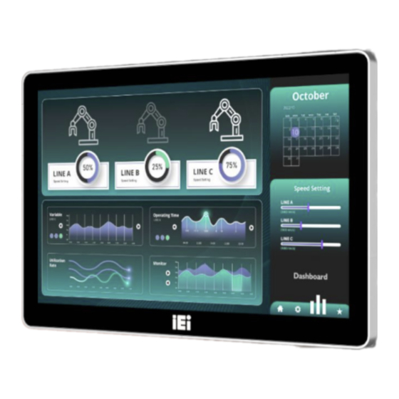
AFL4-W07-EHL Panel PC 1.1 Overview Figure 1-1: AFL4-W07-EHL Panel PC The AFL4-W07-EHL is a 7" panel PC powered by Intel® Celeron® J6412 Processor, featuring a variety of functions and peripherals. The Intel® Celeron® Processor J6412 is a SoC (System-on-Chip) that ensures optimal memory, graphics, and peripheral I/O support. -
Page 15: Front Panel
AFL4-W07-EHL Panel PC 1.3 Front Panel The front side of the AFL4-W07-EHL is a flat panel LCD touchscreen surrounded by an aluminum frame. (Figure 1-2). Figure 1-2: Front View 1.4 Rear Panel The rear panel provides access to retention screw holes that support VESA 75 mounting. -
Page 16: System Specifications
BIOS menu first and choose which operating system will be installed. Otherwise, the USB 2.0 and USB 3.2 Gen 2 ports may not be detected. 1.6 System Specifications The technical specifications for the AFL4-W07-EHL systems are listed in Table 1-1. Specification AFL4-W07-EHL LCD Size 7"... - Page 17 AFL4-W07-EHL Panel PC Brightness (cd/m LCD Color 16.2M Contrast Ratio 800:1 Viewing Angle (H-V) 170°/170° Backlight MTBF 20000 hours Touchscreen PCAP with USB interface (anti-UV/AG coating) Touch Controller EETI 81 Series CPU (SoC) Intel® Celeron® Processor J6412 Dual channel LPDDR4x 8GB on board Ethernet LAN1: Intel®...
-
Page 18: Wlan/Bluetooth Frequency Range And Power
AFL4-W07-EHL Panel PC Safety/EMC CE/EMC, FCC, RED (Class A) Power Requirement Thermal Solution Fanless ErP 2009/125/EC Windows10 / Linux 1 x 2.5GbE LAN 2 x RS-232/422/485 by DB9 1 x USB2.0 1 x HDMI output 2 x USB 3.2 Gen 2... -
Page 19: Dimensions
AFL4-W07-EHL Panel PC 1.7 Dimensions The AFL4-W07-EHL dimensions are shown below. Figure 1-5: AFL4-W07-EHL Dimensions (mm) Page 18... -
Page 20: Unpacking
AFL4-W07-EHL Panel PC Chapter Unpacking Page 19... -
Page 21: Unpacking
AFL4-W07-EHL Panel PC 2.1 Unpacking To unpack the panel PC, follow the steps below: WARNING! The front side LCD screen has a protective plastic cover stuck to the screen. Only remove the plastic cover after the panel PC has been properly installed. -
Page 22: Optional Items
AFL4-W07-EHL Panel PC The AFL4-W07-EHL panel PC is shipped with the following components: Quantity Item Image AFL4-W07-EHL panel PC 60 W power adapter Power cord Table 2-1: Packing List If any of the above items are missing or damaged, contact the distributor or sales representative immediately. -
Page 23: Table 2-2: Optional Items
AFL4-W07-EHL Panel PC Item and Part Number Image (P/N: ARM-11-RS) Stand for VESA 75 (P/N: STAND-C12-R10) LCD monitor stand with adjustable hinge (P/N: VSTAND-A07-R11) Table 2-2: Optional Items Page 22... -
Page 24: Installation
AFL4-W07-EHL Panel PC Chapter Installation Page 23... -
Page 25: Anti-Static Precautions
Electrostatic discharge (ESD) can cause serious damage to electronic components, including the AFL4-W07-EHL. Dry climates are especially susceptible to ESD. It is therefore critical that whenever AFL4-W07-EHL is accessed internally, or any other electrical component is handled, the following anti-static precautions are strictly adhered Wear an anti-static wristband: Wearing a simple anti-static wristband can ◼... -
Page 26: Installation And Configuration Steps
AFL4-W07-EHL Panel PC Anti-static Discharge: If a user opens the rear panel of the panel PC, to ◼ configure the jumpers or plug in added peripheral devices, ground themselves first and wear an anti-static wristband. 3.3 Installation and Configuration Steps The following installation steps must be followed. -
Page 27: Module Installation
AFL4-W07-EHL Panel PC Figure 3-1: Back Cover Retention Screws 3.5 M.2 Module Installation To install a M.2 module into the AFL4-W07-EHL, please follow the steps below: Remove the back cover. See Figure 3-1. Step 1: Locate the M.2 M-key 2242 card slot. Remove the preinstalled retention screw Step 2: on the standoff of the M.2 M-key card slot as shown in Figure 3-2. -
Page 28: Clear Cmos
Figure 3-3: M.2 Module Installation 3.6 Clear CMOS If the AFL4-W07-EHL fails to boot due to improper BIOS settings, the clear CMOS Button clears the CMOS data and resets the system BIOS information. To do this, push the clear CMOS button for three seconds, then restart the system. The clear CMOS button location is shown in Figure 3-4. -
Page 29: At/Atx Mode Selection
Figure 3-4: Clear CMOS Button Location 3.7 AT/ATX Mode Selection AT or ATX power mode can be used on the AFL4-W07-EHL. The selection is made through an AT/ATX switch located on the side panel (Figure 3-5). Figure 3-5: AT/ATX Switch Location 3.7.1 AT Power Mode... -
Page 30: Mounting The System
AFL4-W07-EHL Panel PC Security surveillance ◼ Point-of-Sale (POS) ◼ Advertising terminal ◼ 3.8 Mounting the System The methods of mounting the AFL4-W07-EHL are listed below. Wall mounting ◼ Arm mounting ◼ Stand mounting ◼ V-Stand mounting ◼ The mounting methods are described below. -
Page 31: Figure 3-6: Wall-Mounting Bracket
AFL4-W07-EHL Panel PC Figure 3-6: Wall-mounting Bracket Insert the four monitor mounting screws provided in the wall mount kit into the Step 6: four screw holes on the real panel of the panel PC and tighten until the screw shank is secured against the rear panel (Figure 3-7). -
Page 32: Figure 3-7: Chassis Support Screws
Ensure that all four of the mounting screws fit snugly into their respective slotted holes. Always keep the AFL4-W07-EHL in landscape orientation when mounting on the wall. NOTE: In the diagram below the bracket is already installed on the wall. -
Page 33: Arm Mounting
3.8.2 Arm Mounting The AFL4-W07-EHL is VESA (Video Electronics Standards Association) compliant and can be mounted on an arm with a 75 mm interface pad. To mount the AFL4-W07-EHL on an arm, please follow the steps below. The arm is a separately purchased item. Please correctly mount the arm onto Step 1: the surface it uses as a base. -
Page 34: Figure 3-9: Arm Mounting Retention Screw Holes
Step 3: panel PC (Figure 3-9). Figure 3-9: Arm Mounting Retention Screw Holes Secure the AFL4-W07-EHL to the interface pad by inserting four retention Step 4: screws through the mounting arm interface pad and into the AFL4-W07-EHL. Figure 3-10: Arm Mounting... -
Page 35: Stand Mounting
AFL4-W07-EHL Panel PC 3.8.3 Stand Mounting To mount the AFL4-W07-EHL using the stand mounting kit, please follow the steps below. Locate the screw holes on the rear of the AFL4-W07-EHL. This is where the Step 1: bracket will be attached. -
Page 36: Figure 3-12: Drill Pilot Holes For V-Stand
AFL4-W07-EHL Panel PC Figure 3-12: Drill Pilot Holes for V-Stand Align the screw holes on the V-Stand with the VESA mount screw holes on the Step 2: system rear panel. Insert the four VESA mount screws into the four screw holes on the system rear Step 3: panel. -
Page 37: Powering On The System
AFL4-W07-EHL Panel PC Align the V-Stand screw holes with the pilot holes on the mounting area. Mount Step 5: the V-Stand by inserting the retention screws into the four pilot holes and tightening them. Adjust the V-Stand to have a best viewing angle to operate the system. -
Page 38: Reset The System
Ensure to connect the power cord to a socket- outlet with earthing connection. Connect the power adapter to the power connector of the AFL4-W07-EHL. The Step 2: power LED on the power button turns on in amber. -
Page 39: Software Installation
AFL4-W07-EHL Panel PC 3.11 Software Installation All the drivers for the AFL4-W07-EHL are available on IEI Resource Download Center (https://download.ieiworld.com). Type AFL4-W07-EHL and press Enter to find all the relevant software, utilities, and documentation. Figure 3-17: IEI Resource Download Center 3.11.1 Driver Download... - Page 40 AFL4-W07-EHL Panel PC Click the driver file name on the page and you will be prompted with the Step 3: following window. You can download the entire ISO file ( ), or click the small arrow to find an individual driver and click the file name to download (...
-
Page 41: System Maintenance
AFL4-W07-EHL Panel PC Chapter System Maintenance Page 40... -
Page 42: System Maintenance Introduction
AFL4-W07-EHL Panel PC 4.1 System Maintenance Introduction If the components of the AFL4-W07-EHL fail they must be replaced. Please contact the system reseller or vendor to purchase the replacement parts. Back cover removal instructions for the AFL4-W07-EHL are described below. -
Page 43: Turn Off The Power
Before any maintenance procedures are carried out on the system, make sure the system is turned off. 4.4 WLAN Card Replacement The AFL4-W07-EHL has one WLAN card. To replace the WLAN card, follow the instructions below. Follow all anti-static procedures. -
Page 44: Figure 4-2: Releasing The Wlan Module
AFL4-W07-EHL Panel PC Disconnect the antenna cables on the WLAN module and remove the retention Step 5: screw to release the WLAN card (Figure 4-2). Figure 4-2: Releasing the WLAN Module Grasp the WLAN module by the edges and carefully pull it out of the socket Step 6: (Figure 4-3). -
Page 45: Reinstalling The Cover
AFL4-W07-EHL Panel PC Push the WLAN module down and secure it with the previously removed Step 8: retention screw. Connect the antenna cables. Step 9: Replace the back cover and secure it using the previously removed retention Step 10: screws. -
Page 46: Interface Connectors
AFL4-W07-EHL Panel PC Chapter Interface Connectors Page 45... -
Page 47: Peripheral Interface Connectors
AFL4-W07-EHL Panel PC 5.1 Peripheral Interface Connectors The AFL4-W07-EHL panel PC motherboard comes with a number of peripheral interface connectors and configuration jumpers. The connector locations are shown in Figure 5-1 and Figure 5-2. The connector pinouts for these connectors are listed in the following sections. -
Page 48: Internal Peripheral Connectors
Internal peripheral connectors are found on the motherboard and are only accessible when the motherboard is outside of the chassis. The table below shows a list of the peripheral interface connectors on the AFL4-W07-EHL motherboard. Pinouts of these connectors can be found in the following sections. -
Page 49: Spi Flash Header (Jbios1)
AFL4-W07-EHL Panel PC 5.2.2 SPI Flash Header (JBIOS1) PIN NO. DESCRIPTION +1.8V SPI_CS# SPI_SO SPI_CLK SPI_SI Table 5-3: SPI Flash Header (JBIOS1) Pinouts 5.2.3 EC Debug Header (EC_DEBUG1) PIN NO. DESCRIPTION EDICS EDIDO EDICLK EDIDI Table 5-4: EC Debug Header (EC_DEBUG1) Pinouts 5.2.4 Speaker Connector (SPK_L1) -
Page 50: Rfid Connector (Rfid_Usb1)
AFL4-W07-EHL Panel PC PIN NO. DESCRIPTION PIN NO. DESCRIPTION SPI_SI Table 5-6: EC Flash Header (JEC1) Pinouts 5.2.6 RFID Connector (RFID_USB1) PIN NO. DESCRIPTION -DATA5 +DATA5 Table 5-7: RFID Connector (RFID_USB1) Pinouts 5.2.7 Digital MIC Connector (DMIC1) PIN NO. DESCRIPTION... -
Page 51: Smbus Connector (Smb1)
AFL4-W07-EHL Panel PC 5.2.9 SMBus Connector (SMB1) PIN NO. DESCRIPTION SMB_DATA SMB_CLK Table 5-10: SMBus Connector (SMB1) Pinouts 5.2.10 Battery Connector (BAT1) PIN NO. DESCRIPTION PIN NO. DESCRIPTION +V3.3A_DSW Table 5-11: Battery Connector (BAT1) Pinouts 5.2.11 M.2 A-Key Slot (M2_AE1) PIN NO. -
Page 52: M-Key Slot (M2_M1)
AFL4-W07-EHL Panel PC PIN NO. DESCRIPTION PIN NO. DESCRIPTION PETP0 PETN0 PERP0 PERN0 PCIE_CLK+ PCIE_CLK- PLT_RST CLKREQ0# Pull up PCIE_WAKE W_DIS I2C_DAT I2C_CLK +3.3V +3.3V +3.3V Table 5-12: M.2 A-Key Slot (M2_AE1) Pinouts 5.2.12 M.2 M-Key Slot (M2_M1) PIN NO. - Page 53 AFL4-W07-EHL Panel PC PIN NO. DESCRIPTION PIN NO. DESCRIPTION PETP0 +3.3V +3.3V PERN1 +3.3V PERP1 PETN1 PETP1 PERN2 PERP2 PETN2 PETP2 DEVSLP PERN3 PERP3 PETN3 PETP3 PERST# CLKREQ PCIECLKN PEWAKE PCIECLKP Module Key Module Key Module Key Module Key Module Key...
-
Page 54: Lvds Connector (Lvds1)
AFL4-W07-EHL Panel PC PIN NO. DESCRIPTION PIN NO. DESCRIPTION Table 5-13: M.2 M-Key Slot (M2_M1) Pinouts 5.2.13 LVDS Connector (LVDS1) PIN NO. DESCRIPTION PIN NO. DESCRIPTION LCD_VCOM LCD_VCC LCD_VCC LCD_RST LCD_STBYB LVDS_A0- LVDS_A0+ LVDS_A1- LVDS_A1+ LVDS_A2- LVDS_A2+ LVDS_A_CLK- LVDS_A_CLK+ LVDS_A3-... -
Page 55: Flash Descriptor Security Override
Short 2-3 High = Enabled (OVERIDE) Table 5-16: J_FLASH1 Connector 5.4 External Interface Panel Connectors The table below lists the rear panel connectors on the AFL4-W07-EHL motherboard. Pinouts of these connectors can be found in the following sections. Connector Type Label USB 2.0 Connectors... -
Page 56: Usb 3.2 Gen 2 Connector (Usb_Con2/3)
AFL4-W07-EHL Panel PC 5.4.2 USB 3.2 Gen 2 Connector (USB_CON2/3) PIN NO. DESCRIPTION USB_PN- USB_PP+ USB3_RX_N USB3_RX_P USB3_TX_N USB3_TX_P Table 5-19: USB 3.2 Gen 2 Connector (USB_CON2/3) Pinouts 5.4.3 DC JACK (PWR1) PIN NO. DESCRIPTION PIN NO. DESCRIPTION VCC 12V Table 5-20: DC JACK (PWR1) 5.4.4 Power Button (PWR_SW1) -
Page 57: Gbe Lan Connector (J_Lan1)
AFL4-W07-EHL Panel PC PIN NO. DESCRIPTION DATA SET READY (DSR) REQUEST TO SEND (RTS1/2) CLEAR TO SEND (CTS1/2) RING INDICATOR (RI1/2) Table 5-22: RS-232/422/485 serial ports (COM1/2) Pinouts 5.4.6 2.5GbE LAN Connector (J_LAN1) PIN NO. DESCRIPTION PIN NO. DESCRIPTION TRD1P2... -
Page 58: Table 5-24: Hdmi1 Connector (Hdmi1) Pinouts
AFL4-W07-EHL Panel PC PIN NO. DESCRIPTION PIN NO. DESCRIPTION Table 5-24: HDMI1 Connector (HDMI1) Pinouts Page 57... -
Page 59: A Regulatory Compliance
AFL4-W07-EHL Panel PC Appendix Regulatory Compliance Page 58... - Page 60 AFL4-W07-EHL Panel PC DECLARATION OF CONFORMITY This equipment is in conformity with the following EU directives: EMC Directive (2014/30/EU) Low-Voltage Directive (2014/35/EU) RoHS II Directive (2015/863/EU) If the user modifies and/or install other devices in the equipment, the CE conformity declaration may no longer apply.
- Page 61 AFL4-W07-EHL Panel PC Česky [Czech] IEI Integration Corp tímto prohlašuje, že tento zařízení je ve shodě se základními požadavky a dalšími příslušnými ustanoveními směrnice 2014/53/EU. Dansk [Danish] IEI Integration Corp erklærer herved, at følgende udstyr overholder de væsentlige krav og øvrige relevante krav i direktiv 2014/53/EU.
- Page 62 AFL4-W07-EHL Panel PC Malti [Maltese] IEI Integration Corp jiddikjara li dan prodott jikkonforma mal-ħtiġijiet essenzjali u ma provvedimenti oħrajn relevanti li hemm fid-Dirrettiva 2014/53/EU. Magyar [Hungarian] IEI Integration Corp nyilatkozom, hogy a berendezés megfelel a vonatkozó alapvetõ követelményeknek és az 2014/53/EU irányelv egyéb elõírásainak.
- Page 63 AFL4-W07-EHL Panel PC ROHS STATEMENT The label on the product indicates this product conforms to European (EU) Restriction of Hazardous Substances (RoHS) that set maximum concentration limits on hazardous materials used in electrical and electronic equipment. UKCA WARNING Page 62...
- Page 64 AFL4-W07-EHL Panel PC FCC WARNING This equipment complies with Part 15 of the FCC Rules. Operation is subject to the following two conditions: This device may not cause harmful interference, and This device must accept any interference received, including interference that may cause undesired operation.
-
Page 65: B Safety Precautions
AFL4-W07-EHL Panel PC Appendix Safety Precautions Page 64... -
Page 66: Safety Precautions
Electric shocks can occur if the AFL4-W07-EHL chassis is opened when it ◼ is running. To avoid risk of electric shock, this device must only be connected to a supply mains with protective earth. -
Page 67: Anti-Static Precautions
Electrostatic discharge (ESD) can cause serious damage to electronic components, including the AFL4-W07-EHL. Dry climates are especially susceptible to ESD. It is therefore critical that whenever the AFL4-W07-EHL is opened and any of the electrical components are handled, the following anti-static precautions are strictly adhered to. -
Page 68: Product Disposal
AFL4-W07-EHL Panel PC Self-grounding: Before handling any electrical component, touch any ◼ grounded conducting material. During the time the electrical component is handled, frequently touch any conducting materials that are connected to the ground. Use an anti-static pad: When configuring or working with an electrical ◼... -
Page 69: Maintenance And Cleaning Precautions
B.2.1 Maintenance and Cleaning Prior to cleaning any part or component of the AFL4-W07-EHL, please read the details below. Except for the LCD panel, never spray or squirt liquids directly onto any ◼... -
Page 70: Cleaning Tools
In such case, the product will be explicitly mentioned in the cleaning tips. Below is a list of items to use when cleaning the AFL4-W07-EHL. Cloth– Although paper towels or tissues can be used, a soft, clean piece of ◼... -
Page 71: C Watchdog Timer
AFL4-W07-EHL Panel PC Appendix Watchdog Timer Page 70... - Page 72 AFL4-W07-EHL Panel PC NOTE: The following discussion applies to DOS. Contact IEI support or visit the IEI website for drivers for other operating systems. The Watchdog Timer is a hardware-based timer that attempts to restart the system when it stops working. The system may stop working because of external EMI or software bugs.
- Page 73 AFL4-W07-EHL Panel PC NOTE: The Watchdog Timer is activated through software. The software application that activates the Watchdog Timer must also deactivate it when closed. If the Watchdog Timer is not deactivated, the system will automatically restart after the Timer has finished its countdown.
-
Page 74: D Hazardous Materials Disclosure
AFL4-W07-EHL Panel PC Appendix Hazardous Materials Disclosure Page 73... -
Page 75: Rohs Ii Directive (2015/863/Eu)
AFL4-W07-EHL Panel PC D.1 RoHS II Directive (2015/863/EU) The details provided in this appendix are to ensure that the product is compliant with the RoHS II Directive (2015/863/EU). The table below acknowledges the presences of small quantities of certain substances in the product, and is applicable to RoHS II Directive (2015/863/EU). -
Page 76: China Rohs
AFL4-W07-EHL Panel PC D.2 China RoHS 此附件旨在确保本产品符合中国 RoHS 标准。以下表格标示此产品中某有毒物质的含量符 合中国 RoHS 标准规定的限量要求。 本产品上会附有”环境友好使用期限”的标签,此期限是估算这些物质”不会有泄漏或突变”的 年限。本产品可能包含有较短的环境友好使用期限的可替换元件,像是电池或灯管,这些元 件将会单独标示出来。 部件名称 有毒有害物质或元素 壳体 印刷电路板 金属螺帽 电缆组装 风扇组装 电力供应组装 电池 O: 表示该有毒有害物质在该部件所有物质材料中的含量均在 SJ/T11364-2014 與 GB/T26572- 2011 标准规定的限量要求以下。 X: 表示该有毒有害物质至少在该部件的某一均质材料中的含量超出 SJ/T11364-2014 與 GB/T26572-2011 标准规定的限量要求。 Page 75...
Need help?
Do you have a question about the AFL4-W07-EHL and is the answer not in the manual?
Questions and answers