
Related Manuals for Gladiator Gladiator Garage Works Freezerator GAFZ21XXMK Series


Summary of Contents for Gladiator Gladiator Garage Works Freezerator GAFZ21XXMK Series
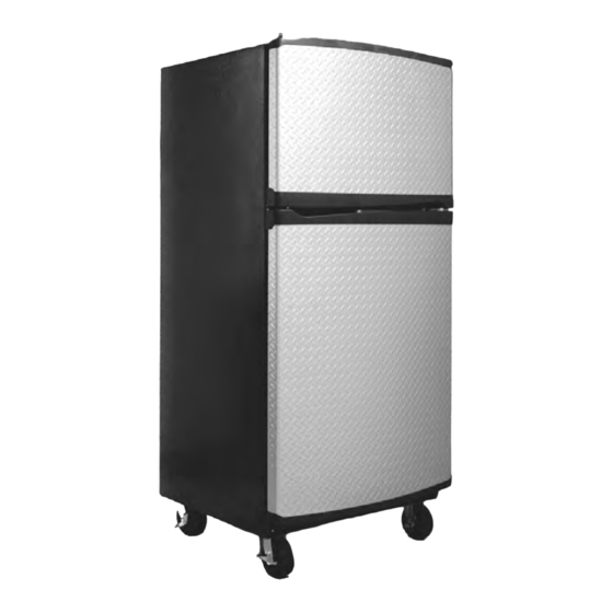
- Page 1 CONSUMER SERVICES TECHNICAL R-98 EDUCATION GROUP PRESENTS GLADIATOR GARAGE WORKS FREEZERATOR Model GAFZ21XXMK00 JOB AID Part No. 8178384...
- Page 2 • Successfully perform necessary repairs. • Successfully return the refrigerator to its proper operational status. WHIRLPOOL CORPORATION assumes no responsibility for any repairs made on our products by anyone other than Authorized Service Technicians. Copyright © 2003, Whirlpool Corporation, Benton Harbor, MI 49022...
-
Page 3: Table Of Contents
TABLE OF CONTENTS Page GENERAL ..........................1-1 Safety First ......................... 1-1 Model & Serial Number Designations ................1-3 Model & Serial Number Label Location ................1-4 Specifications ........................1-5 THEORY OF OPERATION ..................... 2-1 Overview ..........................2-1 COMPONENT ACCESS ......................3-1 Component Locations ...................... - Page 4 Page DIAGNOSTICS & TROUBLESHOOTING ................5-1 Diagnostics ........................5-1 Adaptive Defrost Control (ADC) Test Mode ..............5-1 Troubleshooting Chart ....................... 5-2 WIRING DIAGRAMS & STRIP CIRCUITS ................6-1 Wiring Diagram 1 ....................... 6-1 Wiring Diagram 2 ....................... 6-2 Strip Circuits ........................6-3 - iv -...
-
Page 5: General
GENERAL SAFETY FIRST Your safety and the safety of others is very important. We have provided many important safety messages in this Job Aid and on the appliance. Always read and obey all safety messages. This is the safety alert symbol. This symbol alerts you to hazards that can kill or hurt you and others. - Page 6 ELECTROSTATIC DISCHARGE (ESD) SENSITIVE ELECTRONICS ESD problems are present everywhere. ESD may damage or weaken the electronic control assembly. The new control assembly may ap- pear to work well after repair is finished, but failure may occur at a later date due to ESD Electrical Shock Hazard stress.
-
Page 7: Model & Serial Number Designations
MODEL & SERIAL NUMBER DESIGNATIONS MODEL NUMBER SERIAL NUMBER MODEL NUMBER SERIAL NUMBER 10001 BRAND MANUFACTURING SITE E = Evansville, IN PRODUCT GROUP AC = Accessory YEAR OF PRODUCTION CP = Compactor P = 2003 CS = Cleaning Station WEEK OF PRODUCTION DP = Display For Trade Partner 03 = 3rd Week FL = Flooring... -
Page 8: Model & Serial Number Label Location
MODEL & SERIAL NUMBER LABEL LOCATION The Model/Serial Number Label location is shown below. Model & Serial Number Location (Upper Left Refrigerator Liner) -
Page 9: Specifications
SPECIFICATIONS MODEL NUMBER GAFZ21XXMK Total AHAM Volume (Cu Ft) 21.0 Top Compartment Volume (Cu Ft) 5.67 Freezer Volume (Cu Ft) 15.37 Bottom Compartment Total AHAM Shelf Area (Sq Ft) 29.9 Exterior Dimensions (Nearest 1/8") Cabinet Height (Floor To Top Of Cabinet) (in) 72 3/4"... - Page 10 — NOTES —...
-
Page 11: Theory Of Operation
THEORY OF OPERATION OVERVIEW ™ ™ The Gladiator Garage Works Freezerator During the defrost cycle, if the top compart- a freezer with a top compartment that is con- ment is set to “freezer” mode, the 60 watt vertible to a refrigerator or freezer. Freezerator evaporator cover heater may be used, in addi- is designed to operate properly in the tempera- tion to the defrost heater, to aid in frost removal. - Page 12 — NOTES —...
-
Page 13: Component Access
COMPONENT ACCESS This section instructs you on how to service each component inside the Freezerator. The components and their locations are shown below. COMPONENT LOCATIONS Top Compartment Door Top Compartment Switch & Light Socket Thermostat & Freezer/Refrigerator Selector Switch Auxiliary Heater, Evaporator Fan Motor, Bimetal, Defrost Heater, &... -
Page 14: Removing The Top Compartment Thermostat And The Freezer/Refrigerator Selector Switch
REMOVING THE TOP COMPARTMENT THERMOSTAT AND THE FREEZER/REFRIGERATOR SELECTOR SWITCH Pull the 6-pin wire connectors for the top compartment control components out of the opening and disconnect them (see the round inset in the lower left column). Remove the six hex-head screws from the outer evaporator cover. - Page 15 10. Remove the screw from the top compart- 13. To remove the top compartment ther- ment control housing. mostat: 11. Lift the top compartment control housing a) Pull the knob/baffle off the thermostat from the outer evaporator cover, pull the shaft.
- Page 16 c) Push in on the locking tab of the switch and push it out of the bracket cutout. Bracket...
-
Page 17: Removing The Auxiliary Heater
REMOVING THE AUXILIARY HEATER Peel the auxiliary heater off the outer evaporator cover and install the new one in its place. Outer Evaporator Cover Electrical Shock Hazard Disconnect power before servicing. Replace all parts and panels before operating. Failure to do so can result in death or electrical shock. -
Page 18: Removing The Top Compartment Light Socket And Door Switch
REMOVING THE TOP COMPARTMENT LIGHT SOCKET AND DOOR SWITCH To remove the top compartment light socket: a) Remove the insulation from the hous- ing. Insulation Electrical Shock Hazard Disconnect power before servicing. Replace all parts and panels before operating. Failure to do so can result in death or electrical shock. - Page 19 To remove the door switch: a) Disconnect the wires from the door switch terminals. b) Press down on the locking tab and push the switch out of the housing cutout. Switch Wires Housing Locking Tab Door Switch...
-
Page 20: Removing The Evaporator Fan Motor, Liner Heater Bimetal & Defrost Bimetal, Defrost Heater, And Evaporator
REMOVING THE EVAPORATOR FAN MOTOR, LINER HEATER BIMETAL & DEFROST BIMETAL, DEFROST HEATER, AND EVAPORATOR Remove the two screws from the air tower. Pull the top of the evaporator cover for- ward, and lift the bottom of the tower out of the air supply opening. - Page 21 d) Remove the four hex-head rear bracket To remove either the liner heater bi- screws from the evaporator fan motor metal or the defrost bimetal: housing and remove the motor. a) Pull the bimetal off the tubing. 4 Evap Fan Motor Rear Bracket Screws b) Follow the instructions that were sup- plied with the replacement bimetal to connect the wires.
- Page 22 d) Bend the left, center, and right bottom 11. To remove the evaporator: bracket tabs so that you can remove a) Remove the defrost heater (see step the defrost heater. 10 for the procedure). e) Unclip the bottom left side of the defrost b) Unclip the bimetals from the evapora- heater, pull the heater from the three tor tubing (see the photo under step...
-
Page 23: Removing The Bottom Compartment Thermostat, Defrost Control, Light Socket, And Door Switch
REMOVING THE BOTTOM COMPARTMENT THERMOSTAT, DEFROST CONTROL, LIGHT SOCKET, AND DOOR SWITCH Disconnect the 2-wire and 9-wire control housing connectors and remove the con- trol housing from the unit. Place the hous- ing on a work surface with the component side facing up. - Page 24 To remove the bottom compartment To remove the light socket: thermostat: a) Disconnect the 2 wire connectors from a) Pull the knob off the shaft. the light socket terminals. b) Disconnect the three wire connectors b) Press on the locking tab and push the from the thermostat terminals.
-
Page 25: Removing The Condenser Fan Motor And Ambient Bimetal
REMOVING THE CONDENSER FAN MOTOR AND AMBIENT BIMETAL To remove the condenser fan motor: a) Remove the speed nut from the fan blade and remove the blade. Electrical Shock Hazard Disconnect power before servicing. Replace all parts and panels before operating. - Page 26 c) Disconnect the wire connector from the To remove the ambient bimetal: motor. a) Unclip the bimetal from the compressor process stub. NOTE: When reinstalling the bimetal on the process stub, keep the bimetal as close to the compressor Motor Connector as possible.
-
Page 27: Removing The Relay/Overload And Run Capacitor Assembly And The Compressor
REMOVING THE RELAY/OVERLOAD AND RUN CAPACITOR ASSEMBLY AND THE COMPRESSOR b) Pull the relay/overload and run capaci- tor assembly from the compressor pins. c) Disconnect the 2-pin connector from the relay/overload and run capacitor assembly. Electrical Shock Hazard Disconnect power before servicing. 2-Pin Wire Connector Replace all parts and panels before operating. - Page 28 To remove the compressor: Compressor Suction Line a) Remove the relay/overload and run ca- pacitor assembly from the compressor pins (see step 4). b) Access the sealed system and dis- charge the refrigerant into an approved recovery system. c) Unbraze the suction and discharge lines.
-
Page 29: Removing A Caster
REMOVING A CASTER Remove the two 1/2″ and two 3/8″ bolts from the caster bracket and remove the caster assembly. 1/2″ Bolts Electrical Shock Hazard 3/8″ Bolts Disconnect power before servicing. Replace all parts and panels before operating. Failure to do so can result in death or electrical shock. -
Page 30: Removing A Roller And Condenser Fan Motor Housing
REMOVING A ROLLER AND CONDENSER FAN MOTOR HOUSING To remove a rear roller: a) Remove the 1/2″ and two 3/8″ bolts from the rear of the unit. 1/2″ Bolt Rear Of Unit Electrical Shock Hazard Disconnect power before servicing. Replace all parts and panels before operating. - Page 31 To remove a front roller: d) Lower the front of the base until the round head of the axle pin is below the a) Remove the 1/2″ and two 3/8″ bolts bottom edge of the cabinet. from the rear of the unit on each side e) Pull the axle pin from the front roller and (see the photo in step 7a).
- Page 32 c) Push the condenser fan motor housing towards the front of the unit until the pin is out of the base holder, then tilt the top of the housing, and remove it from the unit. Remove Pin Motor Housing Pull To Side From Base &...
-
Page 33: Component Testing
COMPONENT TESTING Before testing any of the components, perform • Check all connections before replacing com- the following checks: ponents, looking for broken or loose wires, failed terminals, or wires not pressed into • Control failure can be the result of corrosion connectors far enough. -
Page 34: Defrost Bimetal & Defrost Heater
Electrical Shock Hazard Disconnect power before servicing. Replace all parts and panels before operating. Failure to do so can result in death or electrical shock. DEFROST BIMETAL & To test the defrost bimetal: DEFROST HEATER a) Touch the ohmmeter test leads to the test plug pins with the pink and brown wires. -
Page 35: Auxiliary Heater
Electrical Shock Hazard Disconnect power before servicing. Replace all parts and panels before operating. Failure to do so can result in death or electrical shock. AUXILIARY HEATER LINER HEATER Liner Heaters Refer to page 3-5 for the procedure for servic- ing the auxiliary heater. -
Page 36: Liner Heater Bimetal
Electrical Shock Hazard Disconnect power before servicing. Replace all parts and panels before operating. Failure to do so can result in death or electrical shock. LINER HEATER BIMETAL AMBIENT BIMETAL Refer to page 3-13 for the procedure for servic- Refer to page 3-8 for the procedure for servic- ing the ambient bimetal. -
Page 37: Bottom Compartment Thermostat
Electrical Shock Hazard Disconnect power before servicing. Replace all parts and panels before operating. Failure to do so can result in death or electrical shock. BOTTOM COMPARTMENT DOOR SWITCH THERMOSTAT Refer to pages 3-6 and 3-11 for the procedures Refer to page 3-11 for the procedure for servic- for servicing a door switch. -
Page 38: Relay/Overload & Run Capacitor
Electrical Shock Hazard Disconnect power before servicing. Replace all parts and panels before operating. Failure to do so can result in death or electrical shock. RELAY/OVERLOAD & COMPRESSOR RUN CAPACITOR Run Capacitor Relay/Overload Refer to page 3-15 for the procedure for servic- Start (S) Run (M) ing the relay/overload &... -
Page 39: Diagnostics & Troubleshooting
DIAGNOSTICS & TROUBLESHOOTING DIAGNOSTICS Test Method #2 ADAPTIVE DEFROST CONTROL (ADC) TEST MODE 1. Disconnect the refrigerator/freezer from the wall outlet for at least 30 seconds. The refrigerator/freezer defrost system can be checked by manually initiating a defrost cycle. 2. Turn the bottom compartment thermostat Off. -
Page 40: Troubleshooting Chart
TROUBLESHOOTING CHART Problem Possible Cause Test Procedure-Action Open convertible compartment See "Component Testing" section for thermostat. test procedure. Defective combination switch. See "Component Testing" section for test procedure. See "Component Testing" section for Open 60 watt auxiliary heater. test procedure. Baffle broken or leaking Repair/replace broken baffle or seal Convertible compartment... -
Page 41: Wiring Diagrams & Strip Circuits
WIRING DIAGRAMS & STRIP CIRCUITS WIRING DIAGRAM 1... -
Page 42: Wiring Diagram 2
WIRING DIAGRAM 2... -
Page 43: Strip Circuits
STRIP CIRCUITS DEFROST (TOP COMPARTMENT TO REFRIGERATOR MODE) Bimetal Defrost Heater DEFROST (TOP COMPARTMENT TO FREEZER MODE) Bimetal Defrost Heater Top Compartment 60W Auxiliary Thermostat Freezer Heater YL/RD LB/BK Refrigerator Ambient Bimetal Liner Heater Bimetal Closes @ 25°F Closes @ 55°F 18W Low (Room Temp) Opens @ 40°F... - Page 44 — NOTES —...
- Page 45 — NOTES —...
- Page 46 — NOTES —...
-
Page 47: Product Specifications
PRODUCT SPECIFICATIONS WARRANTY INFORMATION SOURCES IN THE UNITED STATES: FOR PRODUCT SPECIFICATIONS AND WARRANTY INFORMATION CALL: FOR WHIRLPOOL PRODUCTS: 1-800-253-1301 FOR KITCHENAID PRODUCTS: 1-800-422-1230 FOR ROPER PRODUCTS: 1-800-447-6737 FOR TECHNICAL ASSISTANCE WHILE AT THE CUSTOMER’S HOME CALL: THE TECHNICAL ASSISTANCE LINE: 1-800-253-2870... - Page 48 CORPORATION...
Need help?
Do you have a question about the Gladiator Garage Works Freezerator GAFZ21XXMK Series and is the answer not in the manual?
Questions and answers