
Related Manuals for KOBE CH0030SQB (30")


Summary of Contents for KOBE CH0030SQB (30")
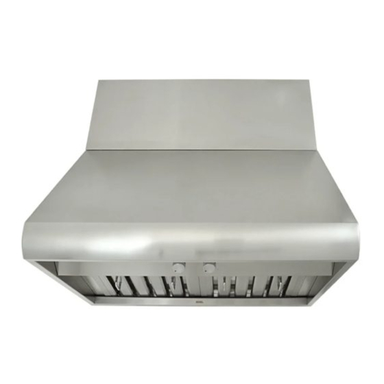
- Page 1 KOBE Brand Range Hood Model No.: CH0030SQB (30”) CH0036SQB (36”) CH0042SQB (42”) CH0048SQB (48”) CH-100 SERIES – 18” HEIGHT INSTALLATION INSTRUCTIONS AND OPERATION MANUAL...
- Page 2 {THIS PAGE LEFT PURPOSELY BLANK}...
-
Page 3: Table Of Contents
- READ AND SAVE THESE INSTRUCTIONS - CONTENTS IMPORTANT SAFETY INSTRUCTIONS... 1 COMPONENTS OF PACKAGE ... 3 INSTALLATION ... 4 UNDER THE CABINET INSTALLATION ...6 STAND ALONE INSTALLATION ...9 OPERATING INSTRUCTIONS ... 12 MAINTENANCE... 13 SPECIFICATIONS ... 15 MEASUREMENTS & DIAGRAMS... 16 PARTS LIST ... -
Page 4: Important Safety Instructions
KOBE RANGE HOODS authorized agents will automatically void the warranty. KOBE RANGE HOODS will not be held responsible for any damages to personal property or real estate or any bodily injuries whether caused directly or indirectly by the range hood. - Page 5 What to Do In The Event Of a Range Top Grease Fire • SMOTHER FLAMES with a close fitting lid, cookie sheet, or metal tray, and then turn off the burner. KEEP FLAMMABLE OR COMBUSTIBLE MATERIAL AWAY FROM FLAMES. If the flames do not go out immediately, EVACUATE THE AREA AND CALL THE FIRE DEPARTMENT or 911.
-
Page 6: Components Of Package
Screw Package for Duct Cover - 1 Model No. CH0048DC-12 for 48” hood KOBE Duct Cover – 1 Screw Package for Duct Cover - 1 OR CONTACT KOBE RANGE HOODS AT (626) 350-1355. 3/16" X 3 /8 " (8 pc) -
Page 7: Installation
INSTALLATION PLEASE READ ENTIRE INSTRUCTION BEFORE PROCEEDING Calculation before Installation To calculate installation, please refer to Table 1. (All calculation in inches.) TABLE 1 A = Height of Floor to Ceiling B = Height of Floor to Counter Top (Standard: 36”) C = Height of Counter Top to Hood Bottom (Recommended 27”... - Page 8 SAFETY WARNING HOOD MAY HAVE VERY SHARP EDGES; PLEASE WEAR PROTECTIVE GLOVES IF REMOVING ANY PARTS FOR INSTALLING, CLEANING OR SERVICING. NOTE: USING ELECTRICAL SCREWDRIVERS MAY CAUSE DAMAGE TO THE HOOD. Installation Table of Contents UNDER THE CABINET INSTALLATION...6 Preparation Before Installation ...6 Hood Installation ...6 Ductwork Installation ...7 Wiring to Power Supply...7...
-
Page 9: Under The Cabinet Installation
UNDER THE CABINET INSTALLATION Preparation Before Installation NOTE: TO AVOID DAMAGE TO YOUR HOOD, PREVENT DEBRIS FROM ENTERING THE VENT OPENING. Decide the location of the venting pipe from the hood • to the outside. Refer to Figure 1. A straight, short vent run will allow the hood to •... -
Page 10: Ductwork Installation
Ductwork Installation 8. Use 8” round steel pipe (follow building codes in your area) to connect the ducting transition on the hood to the ductwork above. Use duct tape to make all joints secure and air tight. Refer to Figure 5. Wiring to Power Supply S A F E T Y W A R N I N G RISK OF ELECTRICAL SHOCK. - Page 11 14. Turn power ON in control panel. Check all lights and fan operation. 15. Make sure to leave this manual for the homeowner Figure 8...
-
Page 12: Stand Alone Installation
***Follow these installations only if installing with an optional duct cover: Preparation Before Installation NOTE: TO AVOID DAMAGE TO YOUR HOOD, PREVENT DEBRIS FROM ENTERING THE VENT OPENING. Decide the location of the venting pipe from the • hood to the outside. Refer to Figure 9. A straight, short vent run will allow the hood to •... -
Page 13: Wiring To Power Supply
mark the leveling point of the hood. Position two mounting screws (not included) on the wall, leaving 1/8” away from the wall. Refer to Figure 13 Align hood-mounting bracket to the two screws on the wall and hook hood into place. Tighten screws to secure hood to the wall. -
Page 14: Duct Cover Installation
Duct Cover Installation Use 8” round steel pipe (follow building codes in your area) to connect the ducting transition on the hood to the ductwork above. to make all joints secure and air tight. Figure 15. Slide the duct cover onto the hood. Use 3/16”... -
Page 15: Operating Instructions
OPERATING INSTRUCTIONS This KOBE hood is equipped with four electronic controls with a 10-second standby startup & 30- second delay shutoff, powerful centrifugal squirrel cage with baffle filters, bright 12-volt 20-watt halogen lights, and heating lamp sockets (lamps not included). The four electronic controls are Light Control, Speed Control A, Speed Control B and the Power Control (On/Off). -
Page 16: Maintenance
MAINTENANCE SAFETY WARNING NEVER PUT YOUR HAND INTO AREA HOUSING THE FAN WHILE THE FAN IS OPERATING. For optimal operation, clean range hood and all baffle/spacer/filter/oil tunnel/oil container regularly. To Clean Hood Surface CAUTION NEVER USE ABRASIVE CLEANERS, PADS, OR CLOTHS. *** Regular care will help preserve the appearance of the hood. - Page 17 To Replace Light Bulb CAUTION HALOGEN LIGHT UNIT MAY BE HOT! WAIT UNTIL UNIT IS COOL. 1. Make sure all controls are off, and range hood is unplugged. 2. Place a flat-head screwdriver between light cover and housing 3. Gently pull defective bulb straight out maximum.
-
Page 18: Specifications
SPECIFICATIONS MODEL / SIZE COLOR CONSUMPTION / AMPERE VOLTAGE NUMBER OF MOTORS DESIGN FAN TYPE: CENTRIFUGAL EXHAUST CONTROLS HALOGEN LIGHTS HEATING LAMP SOCKET HOOD DIMENSION (W X D X H) OPTIONAL ACCESSORIES (Not Included) (W X D X H) HOOD WEIGHT (lbs) Blower Air Capacity (cfm)* Sone** *In House Test Static Pressure “0”. -
Page 19: Measurements & Diagrams
MEASUREMENTS & DIAGRAMS All ( ) are in millimeter. All inch measurements are converted from millimeters. Inch measurements are estimated. MODEL NO: CH0030SQB CH0036SQB CH0042SQB CH0048SQB - FOR UNDER T HE CABINET -... - Page 20 - FOR UNDER T HE CABINET – (Cont.)
- Page 21 - FOR WALL MOUNT (WITH OPTIONAL DUCT COVER) – MODEL NO: CH0030SQB CH0036SQB CH0042SQB CH0048SQB...
- Page 22 Rear Knockout Holes...
- Page 23 - FOR WALL MOUNT (WITH OPTIONAL DUCT COVER) – (Cont.)
- Page 24 Hood-Mounting Bracket 1" (25.4) 1/4" (6.5) 6" (152) 7 - 1/2" (190.5) BAFFLE FILTER & STAINLESS STEEL SPACERS 30" HO O D 42" HO O D 36" HO O D 48" HO O D...
-
Page 25: Parts List
PARTS LIST MODEL NO: CH0030SQB CH0036SQB CH0042SQB CH0048SQB BODY COMPONENTS Hood Casing Ducting Transition Screws (3/16” x 3/8”) Blower Assembly Wiring Box Cover Wiring Box Heat Lamp Socket Screws (3/16” x 3/8”) Heat Lamp Socket Box Oil Tunnel Heat Lamp Panel Halogen Light Panel Halogen Light Screws (3/16”... - Page 26 Optional Duct Cover (Sold Separately)
- Page 27 Blower Assembly DESCRIPTION Screws (3/16” x 3/8”) Air Flow Grill Left Locknut Left Squirrel Cage Motor Right Squirrel Cage Right Locknut Air Chamber MODEL / SIZE PART NO. CH100-4.1 CH100-4.2 CH100-4.3 CH100-4.4 CH100-4.5 CH100-4.6 CH100-4.7 CH100-4.8...
- Page 28 Electrical Assembly DESCRIPTION 21.1 Capacitor 21.2 Electrical Box 21.3 Screws (3/16” x 3/8”) 21.4 Processor Board 21.5 Electrical Box Cover 21.6 Setup Board 21.7 Screws (3/16” x 3/8”) 21.8 Transformer 21.9 Screws (3/16” x 3/8”) 21.3 MODEL / SIZE 21.2 21.9 21.4 21.5...
-
Page 29: Circuit Diagram
CIRCUIT DIAGRAM MODEL NO.: CH0030SQB CH0036SQB PROCESSOR BOARD 120V 60Hz CONTROL BOARD BLACK HALOGEN LIGHT MOTOR TRANSFORMER CAPACITOR 10uF/450V... - Page 30 MODEL NO.: CH0042SQB CH0048SQB CONTROL BOARD PROCESSOR BOARD BLACK HALOGEN LIGHT 120V 60Hz MOTOR TRANSFORMER CAPACITOR 10uF/450V...
-
Page 31: Disclaimer
DISCLAIMER 1. CAREFULLY INSPECT ALL ITEMS FOR DAMAGES BEFORE ACCEPTING DELIVERY. NOTE ANY DAMAGES ON THE FREIGHT BILL OR EXPRESS RECEIPT. REQUEST NAME AND SIGNATURE OF THE CARRIER’S AGENT AND KEEP COPY TO SUPPORT YOUR CLAIM. Upon acceptance of items, owner assumes responsibility for its safe arrival. Report damages to the carrier and file a claim immediately. -
Page 32: Warranty
WARRANTY KOBE Range Hoods, Inc. warrants all products manufactured or supplied by it to be free from defects in workmanship and materials. Its obligations pursuant to this warranty are limited to a period of two years from the date of purchase and to the repair or replacement at its option and subject to the terms and conditions stated below, of any component part, which its examination shall disclose to be so defective. -
Page 33: Consequential Damage
KOBE Range Hoods Agent as applicable, for any traveling expenses and any costs of transporting the range hood or parts thereof to and from the... -
Page 34: Product Registration
KOBE Range Hoods Agent or KOBE Range Hoods as applicable. Keep proof of purchase (original invoice) handy for inspection. - Page 35 {THIS PAGE LEFT PURPOSELY BLANK}...
- Page 36 KOBE Range Hoods 10505 Valley Blvd Suite # 302 El Monte, CA 91731 USA http://www.KOBERangeHoods.com This KOBE hood is manufactured for use in the USA and CANADA only. We do not recommend using this hood overseas as the power supply may not be compatible and may violate the electrical code of that country.
Need help?
Do you have a question about the CH0030SQB (30") and is the answer not in the manual?
Questions and answers