Table of Contents
Advertisement
Quick Links
The Challenge Machinery Company provides owner's manuals on its
products solely as a courtesy to its customers. See the information below
before using this manual.
These manuals are for reference only. These manuals include products which are noncurrent,
unsupported or no longer produced by The Challenge Machinery Company, and are provided solely as
an accommodation to our customers. By providing these manuals, The Challenge Machinery Company
makes no representation or warranty as to the products, their current condition, or their suitability or fitness
for use in any particular application, which are the sole and independent responsibility of the product
owner and user.
Older products may not comply with current safety procedures, guidelines or regulations, and it
is the product owner's and user's responsibility to evaluate the suitability and fitness of the
products in their current use and application. The Challenge Machinery Company makes no
representation, warranty or recommendation regarding any modifications which may be required
on non-current or unsupported products. The Challenge Machinery Company assumes no liability
for any modification or alteration to any Challenge product, and any such modification or
alteration to any Challenge product is not authorized by The Challenge Machinery Company. The
availability of these manuals is solely for the purpose of providing reference information for the products.
This manual may not be complete in all aspects of product maintenance and repair. All products should
be used only by qualified and properly trained personnel, following proper safety procedures. All
products should be regularly inspected and maintained, and their condition, application and use should
be periodically evaluated by qualified personnel. Only qualified and properly trained technicians should
perform maintenance, repair and replacement procedures. Attempting these procedures without proper
training may cause machine damage or operator injury!
Products may be unsupported by The Challenge Machinery Company due to age or the unavailability of
parts from their original manufacturer. No parts or product support will be available to repair or maintain
unsupported products. Older products may not be UL listed (if the product does not have a UL label it is
not a listed product), and may not comply with applicable installation or other regulations or requirements
if relocated to a new facility. Many municipalities require a product to be UL listed before an electrician
will connect power to them. Often the cost of updating an older product to comply with current safety
regulations is greater than the value of the product.
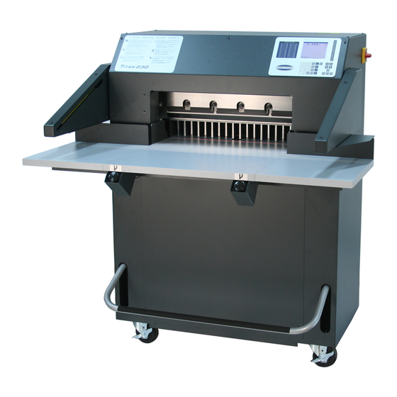
TITAN 230
Technical Service and Parts Manual
Serial Numbers:
120249 through 159999,
230-B-150000 and up
Sold and Serviced by
The Challenge Machinery Company
6125 Norton Center Drive
Norton Shores, MI 49441-6081 USA
F.230-BT
ChallengeMachinery.com
Oct. 2017
Advertisement
Table of Contents

Related Manuals for Challenge TITAN 230


Summary of Contents for Challenge TITAN 230
- Page 1 Products may be unsupported by The Challenge Machinery Company due to age or the unavailability of parts from their original manufacturer. No parts or product support will be available to repair or maintain unsupported products.
-
Page 2: Introduction
Challenge® is a registered trademark of The Challenge Machinery Company 6125 Norton Center Drive Norton Shores, MI 49441-6081 Copyright© 2013 by The Challenge Machinery Company. All rights reserved. Printed in the U.S.A... -
Page 3: Table Of Contents
1.0 Introduction TABLE OF CONTENTS 1.0 Introduction ............................2 2.0 Safety ..............................5 2.1 Precautions ...........................5 2.2 Power Lockout Procedure ......................5 2.3 Warning Label Definitions ......................6 3.0 Maintenance Guide ...........................7 3.1 Troubleshooting ..........................8 3.2 Description of Error Messages .....................9 3.3 Sensor Data Abbreviations ......................11 3.4 Routine Maintenance ......................... - Page 4 1.0 Introduction 4.35 Power Panel Label w/fuses ...................... 90 5.0 Safety Systems Test ........................92...
-
Page 5: Safety
2.0 Safety 2.0 Safety 2.1 Precautions This machine is designed for one-person operation. Never operate the machine with more than one person. Safe use of this machine is the responsibility of the operator. Use good judgment and common sense when working with and around this machine. -
Page 6: Warning Label Definitions
2.0 Safety 2.3 Warning Label Definitions The following warning labels are found at various locations on your machine. Read and understand the meaning of each symbol. If a label is lost from the machine, it should be replaced. HAZARDOUS AREA Disconnect power before cleaning, servicing, or making adjustments not requiring power. -
Page 7: Maintenance Guide
Challenge. The Challenge Machinery Company assumes no liability for any modification or alteration to any Challenge products, and any such modification or alteration to any Challenge product is not authorized by The Challenge Machinery Company. Any... -
Page 8: Troubleshooting
3.0 Maintenance Guide 3.1 Troubleshooting WON’T START Fuse Blown/ Circuit Breaker tripped Power cord disconnected. Main power switch not turned on. BACKGAUGE DISPLAY INACCURATE Preset circuit board malfunction. Encoder malfunction. Main circuit board malfunction. BACKGAUGE DISPLAY INACCURATE - BY CONSTANT AMOUNT Backgauge needs accuracy adjustment. -
Page 9: Description Of Error Messages
3.0 Maintenance Guide Hydraulic fluid low. Voltage supply is low. KNIFE STARTS DOWN BEFORE CLAMP REACHES TABLE Knife down sequence valve setting incorrect. Clamp pressure set too low. KNIFE WON’T RETURN UP Solenoid defective. Limit switch out of adjustment. Cylinder disconnected from bracket. Sequence valve misadjusted. - Page 10 3.0 Maintenance Guide Message Description Test Lubricate Machine Lubricate machine alarm Have machine lubricated Memory Failed A memory error occurred during test Encoder wires 9 & 10 are Should only occur during initial Replace encoder reversed assembly otherwise is an encoder error Memory Locked Tried to change a locked...
-
Page 11: Sensor Data Abbreviations
3.0 Maintenance Guide 3.3 Sensor Data Abbreviations Abbreviations Standby Description Location LEFTCUT Left Cut Button Lower front of table RGHTCUT Right Cut Button Lower front of table KNFLAT Knife Latch Proximity Switch Left side of cutter opening HYDLAT Motor Starter Relay Status Right side of power panel KNFDWN Knife Down Proximity Switch... -
Page 12: Monthly
Empty the hydraulic tank and refill with 1 gallon of International Standards Organization Viscosity Grade 100 (ISO VG 100) rust, oxidation, and foam inhibiting hydraulic fluid (Challenge part no.: S-1991). NOTE: NEVER use automatic transmission fluid or brake fluid as a substitute for the correct hydraulic fluid. -
Page 13: Oil And Grease
3.0 Maintenance Guide 3.6 Oil and Grease Turn the power off and disconnect the power cord. Open the top hood for access. Parts requiring oiling are marked with red paint. See figures Figure 3 through Figure 10 starting on page 13 for oil and grease locations. - Page 14 3.0 Maintenance Guide Figure 5 – Knife Bar Figure 6 – Knife Bar Link – L.H. Side, Lower Figure 7 – Knife Bar Link – R.S., Lower Knife Bar Knife Cylinder Bracket, Upper...
-
Page 15: Adjustments
3.0 Maintenance Guide Figure 8 & Figure 9 –Clamp Guides Figure 10 – Lead Screw and Backgauge Guide 3.7 Adjustments Several of the following tests require the machine to be operational for checking and adjusting. Be very careful that tools and other people are clear of moving parts and that the cutter is not accidentally operated while adjustments are being made. -
Page 16: Backgauge Gib Adjustments
3.0 Maintenance Guide If alignment is necessary, loosen the screws that attach the electric eye brackets to the table extensions. Adjust until the “Beam Status” and the Status Indicator” are green then tighten the screws. 3.7.2 Backgauge Gib Adjustments If the backgauge does not stay squared or jumps up and down when jogging paper against it, the backgauge gib screws are probably loose or worn. -
Page 17: Squaring The Backgauge
3.0 Maintenance Guide 7. Run the backgauge back and forth the length of the table using the backgauge glide control. Check for any binding. Readjust if necessary. NOTE: The screws should be tightened to hold the backgauge square against the guide rail. Excessive tightening will cause the backgauge to bind and cause premature wear of all components. -
Page 18: Proximity Switches
3.0 Maintenance Guide Note: Once the backgauge is square, restore power to the machine and check the backgauge accuracy (see the Titan 230 Operator manual) to make sure it is accurate. 3.7.4 Proximity Switches Proximity switches are used to inform the computer of the up and down positions of the knife and clamp. - Page 19 3.0 Maintenance Guide 3.7.4.2 Clamp Up Proximity Switch (Clampup) Make sure the clamp and knife are in the up position. Turn the power switch off and disconnect the power cord. Remove the top front cover and the upper rear cover. Figure 15 Adjust the clamp up proximity switch by loosening the two actuator mounting screws (Figure 15) and sliding the actuator up or down.
-
Page 20: Hydraulic Adjustments
3.0 Maintenance Guide 3.7.4.4 Hydraulic Clamp Up Proximity Switch (Hydup) Make sure the clamp and knife are in the up position. Turn the power switch off and disconnect the power cord. Remove the lower front panel. Figure 17 Adjust the hydraulic clamp up proximity switch (Figure 17) by loosening the two hose clamp screws and sliding the switch plate up or down. - Page 21 3.0 Maintenance Guide Figure 18 1. TURN CLAMP PRESSURE REDUCER VALVE ALL THE WAY IN (Or, if you have the optional electronic clamp pressure control valve, enter Maintenance Mode and chose Knife Adjust, Knife Down). This will close the clamp pressure reducer valve which will allow you to read the main system and knife down pressures in steps 2 and 3 below.
-
Page 22: Line Light Adjustment
3.0 Maintenance Guide 5.000 Set Maximum > Press /\ to Increase Press \/ to Decrease A) Main C) Send B) Job D) Exit Now perform a cut cycle. After the clamp has contacted the table and while the knife bar is coming down, read the pressure on the clamp pressure gauge (Figure 18). -
Page 23: Cleaning
3.0 Maintenance Guide 3.8 Cleaning Before cleaning inside machine, turn off and lockout power, page 5. Hydraulics 1. The vent fan should be wiped off weekly to maintain maximum cooling of the hydraulic system. 2. The hydraulic manifold, fittings, and hoses should be wiped off weekly to maintain maximum cooling. -
Page 24: Schematics & Parts Lists
4.0 Schematics & Parts Lists 4.0 Schematics & Parts Lists 4.1 Main Assembly – Knife 72000 Sheet 1, Rev.”K”... - Page 25 WASHER/SPACER 41008 BRACKET- PROX, KNIFE DOWN 42002 KNIFE BAR 42004 BASE - MACHINED CASTING 42005 ARCH - MACHINED CASTING 42007 KNIFE - TITAN 230 44055 PIN- SPECIAL TAPER 71008 CYL. SPACER BLOCK AA-10018-1 CYLINDER BRACKET WELDMENT E-1152-73 STANDOFF EE-2770-4 PROX. ASM.- KNIFE UP LIMIT PC BOARD –...
-
Page 26: Main Assembly - Clamp
4.0 Schematics & Parts Lists 4.2 Main Assembly – Clamp 72000 sheet 2... - Page 27 4.0 Schematics & Parts Lists Main Assembly- Clamp Parts List PART NO. DESCRIPTION 10002-3 REAR GUIDE 10075-1 ROD- CLAMP 41033 BRACKET- CLAMP UP 42003 CLAMP 42004 BASE - MACHINED CASTING 42005 ARCH - MACHINED CASTING 42010 PULLDOWN - FOOT PEDAL 42013 FALSE CLAMP PLATE ASSEMBLY 42016...
- Page 28 4.0 Schematics & Parts Lists Main Assembly- Clamp Parts List PART NO. DESCRIPTION H-7321-#10 WASHER - #10 SAE PLAIN H-7321-N4 WASHER - #4 SAE PLAIN H-7324-8 WASHER - 1/4 INT TOOTH H-7324-N10 WASHER - #10 INT TOOTH H-7324-N4 WASHER - #4 INT TOOTH H-7327-12 WASHER - 3/8 MEDIUM LOCK H-21S-250-1000...
-
Page 29: Main Assembly - Knife Latch
4.0 Schematics & Parts Lists 4.3 Main Assembly – Knife Latch 72000 sheet 3 PART NO. DESCRIPTION 8815 WASHER - KNIFE SCREWS 10002-2 FRONT GUIDE 41008 BRACKET- PROX, KNIFE DOWN 41120-4 ASSEMBLY- KNIFE LATCH EE-2770 PROX. ASM.- KNIFE LATCH EE-2770-4 PROX. -
Page 30: Main Assembly- Power Panel
4.0 Schematics & Parts Lists 4.4 Main Assembly- Power Panel 72000 sheet 4... - Page 31 4.0 Schematics & Parts Lists Main Assembly- Power Panel Parts List PART NO. DESCRIPTION E-967-1 LIGHT BULB E-1152-74 STANDOFF E-1214-63 CONNECTOR - #10-RING E-1260-1 SOCKET - LINE LIGHT EE-2765-9 POWER PANEL - STANDARD MODELS EE-3481-2 POWER PANEL - TC MODELS H-6423-4 NUT - 1/4-20 HEX KEP H-6423-N10...
-
Page 32: Main Assembly- Table Bottom
4.0 Schematics & Parts Lists 4.5 Main Assembly- Table Bottom 72000 sheet 5 (Serial Numbers 120276 and Below) - Page 33 Main Assembly- Table Bottom Parts List Serial Numbers 120276 and Below PART NO. DESCRIPTION 7954 TIMING BELT- 200XL037 10040-1 BRACKET- PRESET 42001 TABLE - TITAN 230 42019-3 LEADSCREW - 230 42037-1 GUIDE - BACKGAUGE BRACKET 43005-1 NUT- LEADSCREW 43027-2 BRACKET- MOTOR MOUNT...
-
Page 34: Main Assembly- Table Bottom
4.0 Schematics & Parts Lists 4.6 Main Assembly- Table Bottom 72000 sheet 5 (Serial Numbers 120277 and Above) - Page 35 Main Assembly- Table Bottom Parts List Serial Numbers 120277 and Above PART NO. DESCRIPTION 7954_REP001 TIMING BELT- 200XL037 10040-1 BRACKET- PRESET 42001 TABLE - TITAN 230 42019-3 LEADSCREW - 230 42037-1 GUIDE - BACKGAUGE BRACKET 43005-1 NUT- LEADSCREW 43027-2 BRACKET- MOTOR MOUNT...
-
Page 36: Main Assembly- Table Top
4.0 Schematics & Parts Lists 4.7 Main Assembly- Table Top 72000 sheet 6... - Page 37 Main Assembly- Table Top Parts List PART NO. DESCRIPTION 42001 TABLE - TITAN 230 42006 BACKGAGE - TITAN 230 42008 CUT STICK - TITAN 230 42036 BELT - SLOT CLOSURE 43058 SIDE GUIDE - FRONT 43059-1 SIDE GUIDE - REAR 44153...
-
Page 38: Main Assembly- Stand
4.0 Schematics & Parts Lists 4.8 Main Assembly- Stand 72000 sheet 7... - Page 39 4.0 Schematics & Parts Lists Main Assembly- Stand Parts List PART NO. DESCRIPTION 40016-8 MOUNT - VIBRATION 41014 SWIVEL CASTER WITH BRAKE 42057-1 FOOT BRACKET 44084 JACKSCREW - TABLE 51036 FOOT 71009 HYD. UNIT MOUNTING PLATE 72100 STAND WELDMENT - TITAN 230A E-3082 SWITCH - MAIN DISCONNECT E-3083...
-
Page 40: Main Assembly- Foot Pedal
4.0 Schematics & Parts Lists 4.9 Main Assembly- Foot Pedal 72000 sheet 8... - Page 41 4.0 Schematics & Parts Lists Main Assembly- Foot Pedal Parts List PART NO. DESCRIPTION 40016-3 MOUNT- VIBRATION 42009 PEDAL 42010 PULLDOWN - FOOT PEDAL 43021 TAPE, ANTI-SKID 43023 CLEVIS PIN 43024 HAIRPIN COTTER 43077 CABLE- FOOT PEDAL 47136-4 EXTENSION SPRING H-6423-4 NUT - 1/4-20 HEX KEP H-6423-5...
-
Page 42: Main Assembly- Side Tables
4.0 Schematics & Parts Lists 4.10 Main Assembly- Side Tables 72000 sheet 9... - Page 43 4.0 Schematics & Parts Lists Main Assembly- Side Tables Parts List PART NO. DESCRIPTION 42026 BACK PLATE - TABLE EXTENSION 42028 SUPPORT - SIDE TABLES 44158 TABLE EXTENSION H-6910-102404 SCREW - #10-24 X 1/2 BUTTON HEAD CAP H-6918-608 SCREW - 3/8-16 X 1 SOCKET HEAD CAP H-7321-6 WASHER - 3/8 SAE PLAIN H-7327-12...
-
Page 44: Main Assembly- Electric Eyes
4.0 Schematics & Parts Lists 4.11 Main Assembly- Electric Eyes 72000 sheet 10... - Page 45 4.0 Schematics & Parts Lists Main Assembly- Electric Eyes Parts List PART NO. DESCRIPTION 72100 STAND WELDMENT - TITAN 230 EE-3362 ELECTRIC EYE ASSEMBLY H-6913-506 SCREW - 5/16-18 X 3/4 HEX HEAD CAP H-7321-5 WASHER - 5/16 SAE PLAIN H-7327-10...
-
Page 46: Main Assembly- Covers
4.0 Schematics & Parts Lists 4.12 Main Assembly- Covers 72000 sheet 11... - Page 47 Main Assembly- Covers Parts List PART NO. DESCRIPTION 41130 LABEL - SERIAL NUMBER 42022-2 COVER- REAR STAND (TOP) 42025 COVER - TITAN 230 REAR BOTTOM 43028-1 COVER - BACKGAUGE DRIVE 44045 COVER- LEADSCREW 70030 KNIFE LATCH GUARD 71006 COVER - TC CONSOLE BACK...
-
Page 48: Main Assembly- Air Table
4.0 Schematics & Parts Lists 4.13 Main Assembly- Air Table 72000 sheet 12... -
Page 49: Main Assembly- Air Table - Electrical
4.0 Schematics & Parts Lists 4.14 Main Assembly- Air Table - Electrical 72000 sheet 13... -
Page 50: Hydraulic Power Unit - 60 Hz (S/N 130352 And Below)
4.0 Schematics & Parts Lists 4.15 Hydraulic Power Unit – 60 Hz (s/n 130352 and below) H477-6 Rev.A - Manual Pressure Adjustment Valve... -
Page 51: Hydraulic Power Unit - 60 Hz (S/N 130353 And Above)
4.0 Schematics & Parts Lists 4.16 Hydraulic Power Unit – 60 Hz (s/n 130353 and above) H-477-8 Rev.A - Electrically Adjusted Pressure Valve... -
Page 52: Hydraulic Power Unit - 50 Hz (S/N 130352 And Below)
4.0 Schematics & Parts Lists 4.17 Hydraulic Power Unit – 50 Hz (s/n 130352 and below) H-477-7 Rev.A - Manually adjusted Pressure Valve... -
Page 53: Hydraulic Power Unit - 50 Hz (S/N 130353 And Above)
4.0 Schematics & Parts Lists 4.18 Hydraulic Power Unit – 50 Hz (s/n 130353 and above) H-477-11 Rev.A - Electronically adjusted Pressure Valve... -
Page 54: Hyd. Manifold Asm. & Schematic (S/N 130352 And Below)
4.0 Schematics & Parts Lists 4.19 Hyd. Manifold Asm. & Schematic (s/n 130352 and below) HH-476-1 Rev.A - Manually adjusted Pressure Valve... -
Page 55: Hyd. Manifold Asm. & Schematic (S/N 130353 & Above)
4.0 Schematics & Parts Lists 4.20 Hyd. Manifold Asm. & Schematic (s/n 130353 & Above) HH-476-2 Rev.A - Electronically adjusted Pressure Valve... -
Page 56: Blower Assembly - Air Table Option
4.0 Schematics & Parts Lists 4.21 Blower Assembly – Air Table Option 44186 Rev. B... - Page 57 4.0 Schematics & Parts Lists Blower Assembly- Air Table Option (parts list)
-
Page 58: Power Panel Assembly (S/N 130352 And Below)
4.0 Schematics & Parts Lists 4.22 Power Panel Assembly (s/n 130352 and below) EE-2765-3 Rev.F - w/o Electronically adjusted clamp pressure valve (optional) - Page 59 4.0 Schematics & Parts Lists EE-2765-3 Power Panel Assembly (CONT.)
- Page 60 4.0 Schematics & Parts Lists EE-2765-3 Power Panel Assembly – Parts (CONT.) PART NO. DESCRIPTION OF ACCESSORIES 43006-1 PANEL - ELECTRICAL EE-2807-2 P.C.B. ASSEMBLY - CONTROLLER E-2805 STARTER - CONTACTOR E-1429-14 WIRE DUCT - 13-1/2" LONG E-2719-14 COVER - WIRE DUCT, 13-1/2" LONG S-1694 CABLE TIE E-2730-3...
- Page 61 4.0 Schematics & Parts Lists EE-2765-3 Power Panel Assembly – Parts (CONT.) PART NO. DESCRIPTION OF ACCESSORIES EE-2770-4 PROXIMITY SWITCH ASSEMBLY - KNIFE UP EE-2770-2 PROXIMITY SWITCH ASSEMBLY - CLAMP UP EE-2775 CABLE ASSEMBLY - KNIFE LATCH E-2066-12 CONNECTOR - PLUG-IN PCB TERM. BLOCK EE-1688-1 CABLE ASSEMBLY - PRESET E-709-R...
-
Page 62: Power Panel Assembly (S/N 130353 And Above)
4.0 Schematics & Parts Lists 4.23 Power Panel Assembly (s/n 130353 and above) EE-2765-4 Rev.J - Electronically adjusted clamp pressure valve – standard w/fuses... - Page 63 4.0 Schematics & Parts Lists EE-2765-4 Power Panel Assembly (CONT.)
- Page 64 4.0 Schematics & Parts Lists EE-2765-4 Power Panel Assembly – Parts (CONT.) PART NO. DESCRIPTION OF ACCESSORIES 43006-2 PANEL - ELECTRICAL EE-2807-2 P.C.B. ASSEMBLY - CONTROLLER E-2805-6 STARTER - CONTACTOR E-1429-14 WIRE DUCT - 13-1/2" LONG E-2719-14 COVER - WIRE DUCT, 13-1/2" LONG S-1694 CABLE TIE E-2730-3...
- Page 65 4.0 Schematics & Parts Lists EE-2765-4 Power Panel Assembly – Parts (CONT.) PART NO. DESCRIPTION OF ACCESSORIES EE-2770-4 PROXIMITY SWITCH ASSEMBLY - KNIFE UP EE-2770-2 PROXIMITY SWITCH ASSEMBLY - CLAMP UP EE-2775 CABLE ASSEMBLY - KNIFE LATCH E-2066-12 CONNECTOR - PLUG-IN PCB TERM. BLOCK EE-1688-1 CABLE ASSEMBLY - PRESET E-709-R...
- Page 66 4.0 Schematics & Parts Lists 4.24 Power Panel Assembly (with Circuit Breakers) EE-2765-9 Rev.A - Electronically adjusted clamp pressure valve – standard w/circuit breakers...
- Page 67 4.0 Schematics & Parts Lists EE-2765-9 POWER PANEL ASSEMBLY - (CONT.)
- Page 68 4.0 Schematics & Parts Lists EE-2765-9 POWER PANEL ASSEMBLY – PARTS LIS (CONT.) NO. PART NO. DESCRIPTION OF ACCESSORIES 43006-2 PANEL - ELECTRICAL EE-2807-2 P.C.B. ASSEMBLY - CONTROLLER E-2805-6 STARTER - CONTACTOR E-1429-14 WIRE DUCT - 13-1/2" LONG E-2719-14 COVER - WIRE DUCT, 13-1/2" LONG S-1694 CABLE TIE E-2730-3...
- Page 69 4.0 Schematics & Parts Lists EE-2765-9 POWER PANEL ASSEMBLY – PARTS LIST (CONT.) NO. PART NO. DESCRIPTION OF ACCESSORIES EE-3105 CABLE ASSEMBLY - ENCODER EE-2770-3 PROXIMITY SWITCH ASSEMBLY - KNIFE DOWN EE-2770 PROXIMITY SWITCH ASSEMBLY - KNIFE LATCH EE-2770-4 PROXIMITY SWITCH ASSEMBLY - KNIFE UP EE-2770-2 PROXIMITY SWITCH ASSEMBLY - CLAMP UP EE-2775...
- Page 70 4.0 Schematics & Parts Lists 4.25 Electrical Schematic – Basic Machine (s/n 130352 & below) E-2771-6 Rev. “C” – manually controlled clamp pressure valve...
- Page 71 4.0 Schematics & Parts Lists 4.26 Electrical Schematic – Basic Machine (s/n 130353 & above) E-2771-8 Rev. “B” – Electrically adjusted clamp pressure valve – standard (with fuses)
- Page 72 4.0 Schematics & Parts Lists 4.27 Electrical Schematic – Basic Machine (s/n 130353 & above) E-2771-8 Rev.B - Standard Machine with Optional Touch Switches (w/fuses)
- Page 73 4.0 Schematics & Parts Lists Electrical Schematic – Basic Machine (with Circuit Breakers) 4.28 E-2771-12 REV. A - Electrically Adjusted clamp pressure valve – standard (with circuit breakers)
- Page 74 4.0 Schematics & Parts Lists Electrical Schematic – Basic Machine (with Circuit Breakers) 4.29 E-2771-12 REV. A - Electrically Adjusted clamp pressure valve – Ergo Touch Switches...
-
Page 75: Board Assembly - Control
4.0 Schematics & Parts Lists 4.30 P.C. Board Assembly - control EE-2807-2 Rev. F... -
Page 76: Control Console Assembly - Standard, Back Lit Display
4.0 Schematics & Parts Lists 4.31 Control Console Assembly – Standard, Back Lit Display EE-3035-2 Rev.”F”... -
Page 77: Knife Latch Assembly
4.0 Schematics & Parts Lists 4.32 Knife Latch Assembly 41120-4 Rev. B NO. PART NO. DESCRIPTION 11288-28 WASHER/SPACER 41112-2 ASSEMBLY - KNIFE LATCH BLOCK 41115-2 PLATE- KNIFE LATCH 41116-3 ROD- KNIFE LATCH 41117-1 SPRING - EXTENSION 47553-2 LINK ASSEMBLY- KNIFE LATCH 47567 LINK - CHAIN 47567... -
Page 78: Tc' Upgrade (Optional)
4.0 Schematics & Parts Lists 4.33 ‘TC’ Upgrade (Optional) EE-3481-1 Rev.H - TITAN 230B and up Only (with fuses) - Page 79 4.0 Schematics & Parts Lists Power Panel Assembly - parts EE-3481-1...
- Page 80 4.0 Schematics & Parts Lists Power Panel Assembly - parts EE-3481-1 PART NO. DESCRIPTION OF ACCESSORIES 43006-2 PANEL - ELECTRICAL EE-3432-2 P.C.B. ASSEMBLY - TC, I/0 E-2805-6 STARTER - CONTACTOR E-1429-14 WIRE DUCT - 13-1/2" LONG E-2719-14 COVER - WIRE DUCT, 13-1/2" LONG S-1694 CABLE TIE E-2730-3...
- Page 81 4.0 Schematics & Parts Lists Power Panel Assembly - parts EE-3481-1 PART NO. DESCRIPTION OF ACCESSORIES EE-2770-4 PROXIMITY SWITCH ASSEMBLY - KNIFE UP EE-2770-2 PROXIMITY SWITCH ASSEMBLY - CLAMP UP EE-2775 CABLE ASSEMBLY - KNIFE LATCH E-2066-12 CONNECTOR - PLUG-IN PCB TERM. BLOCK EE-1688-1 CABLE ASSEMBLY - PRESET E-1356-( )
- Page 82 4.0 Schematics & Parts Lists EE-3481-2 Rev.A – Power Panel Assembly – TC Upgrade (with 4.34 Circuit Breakers)
- Page 83 4.0 Schematics & Parts Lists Power Panel Assembly – TC Upgrade (CONT.) EE-3481-2...
- Page 84 4.0 Schematics & Parts Lists Power Panel Assembly – parts list – EE-3481-2 NO. PART NO. DESCRIPTION OF ACCESSORIES 43006-2 PANEL - ELECTRICAL EE-3432-2 P.C.B. ASSEMBLY - TC, I/0 E-2805-6 STARTER - CONTACTOR E-1429-14 WIRE DUCT - 13-1/2" LONG E-2719-14 COVER - WIRE DUCT, 13-1/2"...
- Page 85 4.0 Schematics & Parts Lists Power Panel Assembly – parts list– EE-3481-2 NO. PART NO. DESCRIPTION OF ACCESSORIES EE-2770-3 PROXIMITY SWITCH ASSEMBLY - KNIFE DOWN EE-2770 PROXIMITY SWITCH ASSEMBLY - KNIFE LATCH EE-2770-4 PROXIMITY SWITCH ASSEMBLY - KNIFE UP EE-2770-2 PROXIMITY SWITCH ASSEMBLY - CLAMP UP EE-2775 CABLE ASSEMBLY - KNIFE LATCH...
-
Page 86: Electrical Schematic - Basic Machine, 'Tc' Upgrade
4.0 Schematics & Parts Lists 4.34.1 Electrical Schematic – Basic Machine, ‘TC’ Upgrade E-3483 Rev.A - TITAN 230B and up Only (WITH FUSES) - Page 87 4.0 Schematics & Parts Lists Electrical Schematic – Basic Machine – TC Upgrade 4.34.2 E-3483-1 Rev.A - TITAN 230B – STANDARD CUT BUTTONS (WITH CIRCUIT BREAKERS)
- Page 88 4.0 Schematics & Parts Lists Electrical Schematic – Basic Machine – TC Upgrade 4.34.3 E-3483-1 Rev.A - TITAN 230B – ERGO CUT BUITTONS (WITH CIRCUIT BREAKERS)
-
Page 89: Console Assembly, 'Tc' Upgrade (Optional)
4.0 Schematics & Parts Lists 4.34.4 Console Assembly, ‘TC’ Upgrade (Optional) EE-3456-4 Rev.B - TITAN 230B and up Only... - Page 90 4.0 Schematics & Parts Lists 4.35 Power Panel Label w/fuses S-1781-191 Rev.A...
- Page 91 4.0 Schematics & Parts Lists 4.36 Power Panel Label w/Circuit Breakers S-1781-236 Rev.A...
- Page 92 5.0 Safety Systems Test Machine manufacturer CHALLENGE Model TITAN 230 Serial Number __________________ Frequency of test: THESE TESTS SHOULD BE PERFORMED AT THE BEGINNING OF EACH WORK DAY. Turn the power on and press CLEAR to preset the backgauge. Make sure the knife and clamp are in the up position (if they are not, follow the instructions in this manual to send them up).
- Page 93 5.0 Safety Systems Test Please enter date and initials for both tests. Date ______ ______ ______ ______ ______ ______ ______ ______ ______ ______ ______ Test 1 ______ ______ ______ ______ ______ ______ ______ ______ ______ ______ ______ Test 2 ______ ______ ______ ______ ______ ______ ______ ______ ______ ______ ______ Date ______ ______ ______ ______ ______ ______ ______ ______ ______ ______ ______ Test 1 ______ ______ ______ ______ ______ ______ ______ ______ ______ ______ ______...
- Page 94 F.230-BT Oct. 2017...
Need help?
Do you have a question about the TITAN 230 and is the answer not in the manual?
Questions and answers