Table of Contents
Advertisement
Quick Links
Maintenance and Service
Guide
HP Notebook QuickDock
Document Part Number:
432100-001
September 2006
This guide is a troubleshooting reference used for maintaining
and servicing the HP Notebook QuickDock. It provides
comprehensive information on identifying QuickDock features,
components, and spare parts; troubleshooting problems; and
performing disassembly procedures.
Advertisement
Table of Contents

Related Manuals for HP QuickDock


Summary of Contents for HP QuickDock
-
Page 1: Maintenance And Service
HP Notebook QuickDock Document Part Number: 432100-001 September 2006 This guide is a troubleshooting reference used for maintaining and servicing the HP Notebook QuickDock. It provides comprehensive information on identifying QuickDock features, components, and spare parts; troubleshooting problems; and performing disassembly procedures. - Page 2 © Copyright 2006 Hewlett-Packard Development Company, L.P. The information contained herein is subject to change without notice. The only warranties for HP products and services are set forth in the express warranty statements accompanying such products and services. Nothing herein should be construed as constituting an additional warranty. HP shall not be liable for technical or editorial errors or omissions contained herein.
-
Page 3: Table Of Contents
3.1 Serial Number Location ..... . 3–1 3.2 QuickDock Components ..... . 3–2 4 Replacement Preliminaries 4.1 Tools Required . -
Page 4: Specifications
Contents 5 Specifications A Connector Pin Assignments B Power Cord Set Requirements Index Maintenance and Service Guide... -
Page 5: Product Description
Product Description The HP Notebook QuickDock provides an efficient, less-cluttered work environment and improved cable management. HP Notebook QuickDock and HP Expansion Accessory Adapter Maintenance and Service Guide 1–1... - Page 6 Product Description The HP Notebook QuickDock is compatible with the following platforms: ■ HP Pavilion dv9000 Notebook PC ■ HP Pavilion dv6000 Notebook PC ■ HP Pavilion dv2000 Notebook PC ■ HP Pavilion tx1000 Entertainment PC ■ Compaq Presario V6000 Notebook PC ■...
-
Page 7: Features
Product Description 1.1 Features ■ External AC adapter (charges docked computer) ■ Security slot ■ Lights (power connection and docking connection) ■ Connectors: ❏ Expansion cable ❏ Audio-out (headphone) connector ❏ Audio-in (microphone) connector ❏ Universal Serial Bus (USB) 2.0 connectors (6) ❏... -
Page 8: External Components
Product Description 1.2 External Components The external components on the front panel of the QuickDock are shown below and described in Table 1-1. Front Components Table 1-1 Front Components Item Component Function Connection indicator On: The computer is connected and light turned on. - Page 9 Product Description The external components on the left side of the QuickDock are shown below and described in Table 1-2. Left-Side Components Table 1-2 Left-Side Components Item Component Function Expansion cable Connects the QuickDock to a computer. Connection indicator On: The computer is connected and light turned on.
- Page 10 Product Description The external components on the right side of the QuickDock are shown below and described in Table 1-3. Right-Side Components 1–6 Maintenance and Service Guide...
- Page 11 Audio-in (microphone) Connects an optional computer headset jack microphone, stereo array microphone, or monaural microphone. USB ports (2)* Connect optional USB devices. *There are 4 additional USB ports on the rear of the QuickDock. Maintenance and Service Guide 1–7...
- Page 12 Product Description The external components on the rear panel of the QuickDock are shown below and described in Table 1-4. Rear Panel Components 1–8 Maintenance and Service Guide...
-
Page 13: Rear Components
(purchased separately). External monitor port Connects an optional external VGA monitor or projector. RJ-45 (network) jack Connects a network cable. *There are 2 additional USB ports on the right side of the QuickDock. Maintenance and Service Guide 1–9... -
Page 14: Design Overview
■ S-Video-out ■ Serial port CAUTION: To properly ventilate the QuickDock, allow at least a Ä 7.6-cm (3-inch) clearance on the left and right sides of the unit. The computer uses an electric fan for ventilation. The fan is controlled by a temperature sensor and is designed to turn on automatically when high temperature conditions exist. -
Page 15: Connecting To Ac Power
Product Description Connecting to AC Power WARNING: To reduce the risk of electric shock or damage to your Å equipment: ■ Plug the power cord into an electrical outlet that is easily accessible at all times. ■ Disconnect power from the product by unplugging the power cord from the electrical outlet. - Page 16 Product Description To ensure the correct performance of all QuickDock features, connect the QuickDock to an AC power source using the computer AC adapter and power cord. 1. Connect the computer AC adapter to the power connector on the QuickDock 1.
-
Page 17: Connecting The Computer
■ Compaq Presario V6000 Notebook PC ■ Compaq Presario V3000 Notebook PC Refer to Section 1.4, “Using the HP Expansion Accessory Adapter,” if you are connecting a computer that requires the HP Expansion Accessory Adapter. Maintenance and Service Guide 1–13... - Page 18 Product Description To connect the computer to the QuickDock: 1. Press the buttons on the sides of the expansion cable 1. 2. Connect the expansion cable to the computer 2, matching the icon on the computer expansion port with the icon on the end of the expansion cable.
- Page 19 Product Description If the computer is on, the connection indicator light on the expansion cable turns on. Identifying the Connection Indicator Light Maintenance and Service Guide 1–15...
- Page 20 Product Description 3. If the computer is not already turned on: ❏ Press the power button on the computer. Pressing the Computer Power Button ✎ The power button location on the computer varies by computer series and model. 1–16 Maintenance and Service Guide...
- Page 21 – or – ❏ Press the power button on the QuickDock. Pressing the QuickDock Power Button ✎ The power button on the QuickDock allows you to turn the computer on or off when the computer is closed. Maintenance and Service Guide 1–17...
- Page 22 Product Description The power light on the front of the QuickDock turns on. Identifying the QuickDock Power Light 1–18 Maintenance and Service Guide...
-
Page 23: Using The Hp Expansion Accessory Adapter
Product Description 1.4 Using the HP Expansion Accessory Adapter The following computers require use of the HP Expansion Accessory Adapter to connect the computer to the QuickDock: ■ HP Pavilion dv8300 Notebook PC ■ HP Pavilion dv8000 Notebook PC ■... - Page 24 Product Description To connect a computer using the HP Expansion Accessory Adapter: 1. Press the buttons on the sides of the expansion cable 1. 2. Connect the expansion cable to the expansion accessory adapter 2, matching the icon on the expansion cable with the icon on the end of the expansion accessory adapter.
-
Page 25: Troubleshooting
Troubleshooting WARNING: Only authorized technicians trained by HP should repair Å this equipment. All troubleshooting and repair procedures are detailed to allow only subassembly-/module-level repair. Because of the complexity of the individual boards and subassemblies, do not attempt to make repairs at the component level or modifications to any printed wiring board. - Page 26 Turn on the computer. light is off. The QuickDock is not Connect the AC adapter connected to AC power. to the QuickDock and to an AC outlet. The expansion cable on Disconnect the the QuickDock is not fully expansion cable from the...
- Page 27 Solution The computer shuts The QuickDock is not Connect the AC adapter down unexpectedly. connected to AC power, to the QuickDock and to draining the computer an AC outlet. battery. The ports or jacks on the The QuickDock is not...
- Page 28 Headphones or other Headphones or another Disconnect the audio device connected audio device is headphones or other to the QuickDock does connected to the audio device from the not produce sound. headphone jack on the headphone jack on the computer. Using the computer.
- Page 29 The QuickDock is not Connect the AC adapter connected to AC power. to the QuickDock and to an AC outlet. The computer is not Disconnect the connected to the expansion cable from the QuickDock correctly.
-
Page 30: Getting More Information
The manufacturer and model of the printer or other accessories connected to the computer and QuickDock ■ Configuration settings, including contents of the system files To access Customer Care, visit the HP Web site at http://www.hp.com/support 2–6 Maintenance and Service Guide... -
Page 31: Illustrated Parts Catalog
3.1 Serial Number Location When ordering parts or requesting information, provide the QuickDock serial number and model number located on the bottom of the base plate. Serial Number Location Maintenance and Service Guide... -
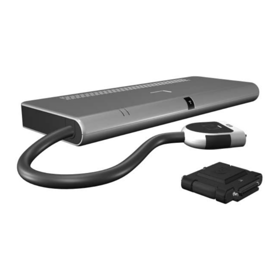
Page 32: Quickdock Components
Illustrated Parts Catalog 3.2 QuickDock Components HP Notebook QuickDock Components Table 3-1 Spare Parts: QuickDock Components Spare Part Item Description Number HP Notebook QuickDock 430326-001 HP Expansion Accessory Adapter 430327-001 3–2 Maintenance and Service Guide... -
Page 33: Replacement Preliminaries
Replacement Preliminaries This chapter provides essential information for proper and safe replacement service. 4.1 Tools Required You will not need any tools to complete the replacement procedures. 4.2 Service Considerations The following sections include some of the considerations that you should keep in mind during replacement procedures. Maintenance and Service Guide 4–1... -
Page 34: Preventing Damage To Removable Drives
Replacement Preliminaries 4.3 Preventing Damage to Removable Drives Removable drives are fragile components that must be handled with care. To prevent damage to the QuickDock, damage to a removable drive, or loss of information, observe the following precautions: ■ Before removing or inserting a hard drive, shut down the system (computer and QuickDock). -
Page 35: Preventing Electrostatic Damage
Replacement Preliminaries 4.4 Preventing Electrostatic Damage Many electronic components are sensitive to electrostatic discharge (ESD). Circuitry design and structure determine the degree of sensitivity. Networks built into many integrated circuits provide some protection, but in many cases, the discharge contains enough power to alter device parameters or melt silicon junctions. -
Page 36: Packaging And Transporting Precautions
Replacement Preliminaries 4.5 Packaging and Transporting Precautions Use the following grounding precautions when packaging and transporting equipment: ■ To avoid hand contact, transport products in static-safe containers, such as tubes, bags, or boxes. ■ Protect all electrostatic-sensitive parts and assemblies with conductive or approved containers or packaging. -
Page 37: Workstation Precautions
Replacement Preliminaries 4.6 Workstation Precautions Use the following grounding precautions at workstations: ■ Cover the workstation with approved static-shielding material Table 4-2, “Static-Shielding Materials” (refer to ■ Use a wrist strap connected to a properly grounded work surface and use properly grounded tools and equipment. ■... -
Page 38: Grounding Equipment And Methods
Replacement Preliminaries 4.7 Grounding Equipment and Methods Grounding equipment must include either a wrist strap or a foot strap at a grounded workstation. ■ When seated, wear a wrist strap connected to a grounded system. Wrist straps are flexible straps with a minimum of one megohm ±10% resistance in the ground cords. - Page 39 Replacement Preliminaries Table 4-1 shows how humidity affects the electrostatic voltage levels generated by different activities. Table 4-1 Typical Electrostatic Voltage Levels Relative Humidity Event Walking across carpet 35,000 V 15,000 V 7,500 V Walking across vinyl floor 12,000 V 5,000 V 3,000 V Motions of bench worker...
- Page 40 Nonoperating -20°C to 60°C -4°F to 140°F ✎ Applicable product safety standards specify thermal limits for plastic surfaces. The QuickDock operates well within this range of temperatures. Relative humidity (noncondensing) Operating 10% to 90% Nonoperating 5% to 95%, 38.7°C (101.6°F) maximum...
- Page 41 Connector Pin Assignments Table A-1 Audio-In (Microphone) Jack Signal Signal Audio signal in Ground Audio signal in Maintenance and Service Guide A–1...
- Page 42 Connector Pin Assignments Table A-2 Audio-Out (Headphone) Jack Signal Signal Audio out, left channel Ground Audio out, right channel A–2 Maintenance and Service Guide...
- Page 43 Connector Pin Assignments Table A-3 External Monitor Port Signal Signal Red analog +5 VDC Green analog Ground Blue analog Monitor detect Not connected DDC 2B data Ground Horizontal sync Ground analog Vertical sync Ground analog DDC 2B clock Ground analog Maintenance and Service Guide A–3...
- Page 44 Connector Pin Assignments Table A-4 RJ-45 (Network) Jack Signal Signal Transmit + Unused Transmit – Receive – Receive + Unused Unused Unused A–4 Maintenance and Service Guide...
- Page 45 Connector Pin Assignments Table A-5 S-Video-Out Jack Signal Signal TV-Ground TV-CD TV-CVBS TV-Ground TV-Ground TV-YD TV-Ground Maintenance and Service Guide A–5...
- Page 46 Connector Pin Assignments Table A-6 Universal Serial Bus Signal Signal +5 VDC Data + Data – Ground A–6 Maintenance and Service Guide...
- Page 47 Power Cord Set Requirements 3-Conductor Power Cord Set The wide range input feature of the QuickDock permits it to operate from any line voltage from 100 to 120 or 220 to 240 volts AC. The power cord set included with the QuickDock meets the requirements for use in the country where the equipment is purchased.
- Page 48 ■ The appliance coupler must meet the mechanical configuration of an EN 60 320/IEC 320 Standard Sheet C13 connector for mating with the appliance inlet on the back of the QuickDock. B–2 Maintenance and Service Guide...
- Page 49 Power Cord Set Requirements Country-Specific Requirements 3-Conductor Power Cord Set Requirements Country/Region Accredited Agency Applicable Note Number Australia EANSW Austria Belgium CEBC Canada Denmark DEMKO Finland FIMKO France Germany Italy Japan METI ✎ NOTES: 1. The flexible cord must be <HAR> Type HO5VV-F, 3-conductor, 1.0 mm² conductor size.
- Page 50 Power Cord Set Requirements 3-Conductor Power Cord Set Requirements (Continued) Country/Region Accredited Agency Applicable Note Number Korea The Netherlands KEMA Norway NEMKO People’s Republic of China Sweden SEMKO Switzerland Taiwan BSMI United Kingdom United States ✎ NOTES: 1. The flexible cord must be <HAR> Type HO5VV-F, 3-conductor, 1.0 mm² conductor size.
- Page 51 Index RJ-45 jack A–4 S-Video-out jack A–5 AC power connect light 1–4 Universal Serial Bus (USB) audio-in jack port A–6 location 1–7 consumer infrared lens 1–4 pin assignments A–1 audio-out jack location 1–7 design overview 1–10 pin assignments A–2 drives, preventing damage 4–2 component video jacks 1–9 electrostatic discharge 4–3 components...
- Page 52 4–1 Adapter right-side components 1–6 connecting 1–19 RJ-45 jack spare part number 3–2 location 1–9 HP Notebook QuickDock pin assignments A–4 components 3–2 spare part number 3–2 S/PDIF digital audio jack 1–9 specifications 5–1 security cable slot 1–7 serial number 3–1...