Advertisement
Quick Links
INSTALLATION & USER INSTRUCTIONS
Focal Point Fires plc.
Christchurch, Dorset BH23 2BT
Tel: 01202 499330
Fax: 01202 499326
www.focalpointfires.co.uk
e : sales@focalpointfires.co.uk
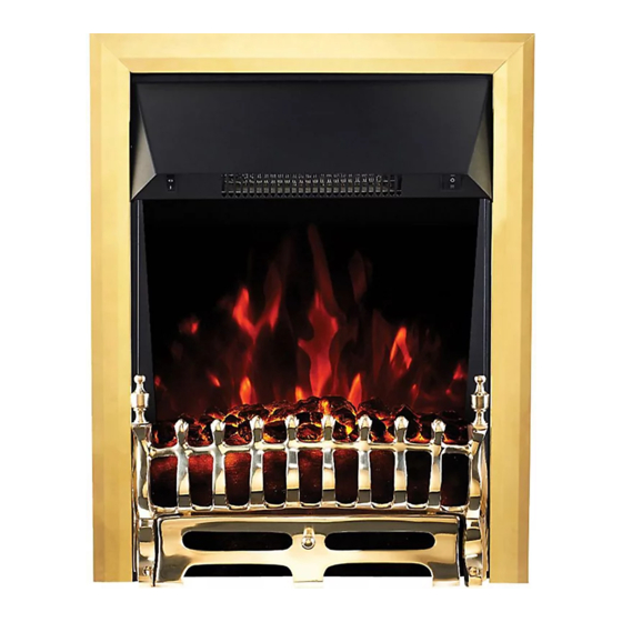
BLENHEIM LED INSET ELECTRIC FIRE
Questions or problems with your appliance?
Don't take it back to the store
just give us a call on
lines open between 9am and 5pm, Monday to Friday
Please note : Except where otherwise stated, all rights,
including copyright in the text, images and layout of this
booklet is owned by Focal Point Fires plc. You are not per-
mitted to copy or adapt any of the content without the
prior written permission of Focal Point Fires plc.
LED ELECTRIC FIRE
MODELS COVERED BY THESE INSTRUCTIONS
FPFBQ257 BLENHEIM LED INSET ELECTRIC FIRE
FPFBQ259 LULWORTH LED INSET ELECTRIC FIRE
FPFBQ409 MODERN LED INSET ELECTRIC FIRE
FRET AND FRAME OPTIONS AVAILABLE
01202 588601
we're here to help
LULWORTH LED INSET ELECTRIC FIRE
All instructions must be handed to the user
1
GB IE
for safekeeping.
Revision D - 04/14
2014 Focal Point Fires plc.
'
Advertisement

Related Manuals for FocalPoint FPFBQ257 BLENHEIM


Summary of Contents for FocalPoint FPFBQ257 BLENHEIM
- Page 1 INSTALLATION & USER INSTRUCTIONS LED ELECTRIC FIRE MODELS COVERED BY THESE INSTRUCTIONS GB IE FPFBQ257 BLENHEIM LED INSET ELECTRIC FIRE FPFBQ259 LULWORTH LED INSET ELECTRIC FIRE FPFBQ409 MODERN LED INSET ELECTRIC FIRE Focal Point Fires plc. FRET AND FRAME OPTIONS AVAILABLE...
-
Page 2: Preliminary Notes
I N S TA L L AT I O N & U S E R I N S T R U C T I O N S GB IE Section Contents Page No. Section Contents Page No. Preliminary Notes Removing the appliance spacer frames Appliance Data Fitting The Decorative Frame And Front 5 Installation Requirements... -
Page 3: Unpacking The Appliance
3.0 INSTALLATION REQUIREMENTS - GB IE CONTINUED DO NOT site in a position where curtains or drapes could cover the appliance. site in a position where other soft materials could cover e.g. below a coat rack. site behind an opening door where mechanical impact/damage could occur. site where the supply cable would become a trip hazard. - Page 4 6.0 INSTALLING THE APPLIANCE - CONTINUED GB IE Method 2 - Screw fixings Using suitable fixings for your wall or surround, mark the centre of your opening and measure 227mm to the left and then again to the right. From there measure from the floor 304mm up the wall.This will be the centre of the screw.
- Page 5 7.0 REMOVING THE APPLIANCE SPACER FRAMES-CON GB IE Step 3: Remove the outer spacer frame. Step 4: To remove the second spacer unscrew four screws using same method used in steps 1, 2 & 3. 8.0 FITTING THE DECORATIVE FRAME AND FRONT The appliance may be supplied with a decorative frame in a variety of finishes.
-
Page 6: Operating The Appliance
9.0 OPERATING THE APPLIANCE GB IE The heater is operated via the use of two switches, one situated on the left hand side of the canopy and one on the right. The switch on the left hand side towards the top, marked (0I), controls the main power to the appliance and switches on the LED display panel. The next switch on the right hand side, with a “single bar”... - Page 7 12.0 GUARANTEE - TERMS AND CONDITIONS GB IE The 3 year guarantee only covers products purchased on or after 1st February 2009. For all gas fires purchased the 3 year guarantee commences from the date of purchase, provided that the following 3 terms and conditions are adhered to: Registration is not required.