Table of Contents
Advertisement
Advertisement
Table of Contents

Related Manuals for Titan TTB541DBT


Summary of Contents for Titan TTB541DBT
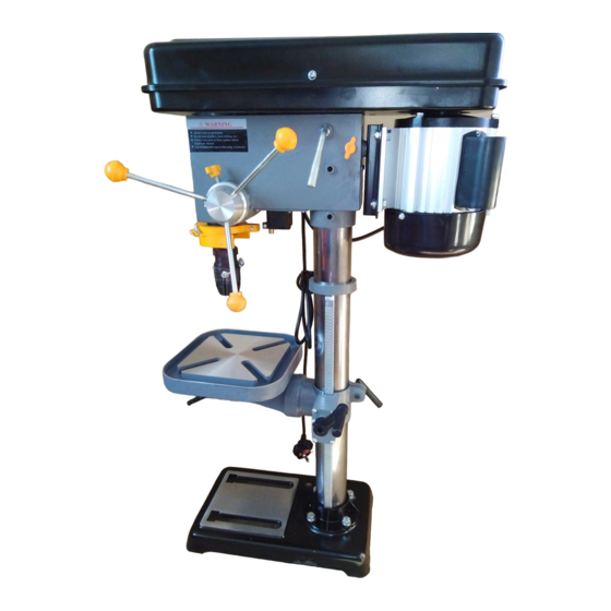
- Page 9 (Fig 1)
- Page 10 Column to Base (7) on the Base (13) and align Place Column holes in the Column with holes in the Base. Attach using Bolt Washer and Spring Washer hole through the Column and into the Base. Base. (Fig 2) Table to Column (16).
- Page 11 Slide the Height Crank(12) over the shaft on the side of the Table Support(15). (Fig 5a) Secure the Crank(12) to the Shaft using the Screw against the flat part of the Shaft. (Fig 5b) Headstock to Column Loosen the two Set Screws on the left side of the Head -stock(17) so they will stay clear while installing it.
- Page 12 Fitting the Chuck Guard Warning:never attempt to use the machine without the Chuck Guard(6) fitted. The telescopi c Chuck Guard(6) is partially assembly onto the machine. Remove three cro ss head screws just below the hinge on the collar. Position the transparent plastic shield into the collar and secure in place with the small screw.
- Page 13 > Make sure the on/off switch is in its off position. > Connect the plug with a suitable socket. > Your product is now ready to be used.
- Page 16 is designated with a rated output of 700 Watts. This To adjust the Work Table(10) height,slacken the Crank(12) at the rear of the table support. (Fig 11) (Fig 12)
- Page 17 (Fig 13) (Fig 14)
- Page 18 switch fitted to the machine. To start the (Fig 15) (Fig 16) (Fig 17)
- Page 19 Drill Bits Soft Wood Hard Wood Plastic Brass Aluminum Mild Steel 1.6mm-4.8mm 3040RPM 2300RPM 2300RPM 2300RPM 3040RPM 2300RPM 5.2mm-9.5mm 2010RPM 1540RPM 2010RPM 1250RPM 2300RPM 1250RPM 9.9mm-15.9mm 1540RPM 780RPM 1540RPM 780RPM 1540RPM 570RPM 17.5mm-25.4mm 780RPM 525RPM 1000RPM 430RPM 1000RPM 370RPM (Fig 18) (Fig 19)
- Page 20 If the power cable is damaged, it must be replaced by the manufacture, service agent or similarly qualified persons in order to avoid a hazard. Always lubricate drill bits with suitable oil when drilling. This will prolong the life of drill bits. Caution: Do not use water-based coolant or any kind of continuous coolant pump.
Need help?
Do you have a question about the TTB541DBT and is the answer not in the manual?
Questions and answers