Advertisement
Advertisement
Table of Contents

Related Manuals for Martin RoboScan 812


Summary of Contents for Martin RoboScan 812
- Page 1 RoboScan 812 user manual...
-
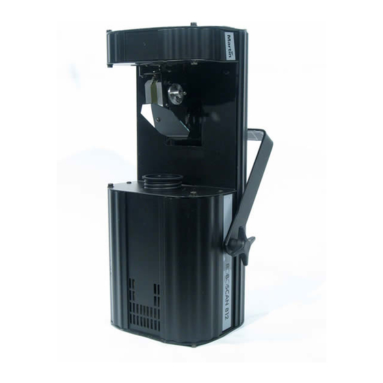
Page 2: Dimension & Overview
© 1998, 1999 Martin Professional A/S, Denmark. All rights reserved. No part of this manual may be reproduced, in any form or by any means, without permission in writing from Martin Professional A/S, Denmark. Printed in Denmark. P/N 35000052, Rev. C... - Page 3 I N T R O D U C T I O N Thank you for selecting the Martin RoboScan 812. It is designed and built to be bright, reli- able and easy to use. With proper setup and maintenance, the RoboScan 812 will provide years of trouble-free operation.
- Page 4 Variable speed control on all functions • Split color and gobo effects • Variable strobe up to 7 Hz • Remote lamp on/off (with Martin-protocol controllers) • Coated precision optics • Adjustable focus • Controllable via Martin and DMX-512 controllers •...
-
Page 5: Installation
I N S T A L L A T I O N The RoboScan 812 is delivered fully adjusted from the factory; only a few setup steps are necessary. Please follow them carefully to get the most out of your new equipment. - Page 6 C h e c k i n g v o l t a g e a n d f r e q u e n c y s e t t i n g s The RoboScan 812 voltage setting must be within 5% of the AC mains supply. The voltage setting may be adjusted to local conditions.
- Page 7 S e t t h e A d d r e s s When using the RoboScan 812 with a controller, you must set the DIP-switch (3) to the start channel, also known as the address, which is the first channel the controller uses to send instructions to the RoboScan 812.
- Page 8 1 and 32. DMX mode: The RoboScan 812 may be operated in tracking or vector mode; see the DMX protocol for details. It uses 5 consecutive DMX channels in tracking mode and 7 consecu- tive DMX channels in vector mode.
-
Page 9: Operation
S t a n d - A l o n e O p e r a t i o n The RoboScan 812 may be operated without a controller in stand-alone mode. In this mode, the fixture performs a random sequence that is triggered by the beat of the music or auto- matically at a set speed. - Page 10 C o n t r o l l a b l e E f f e c t s L a m p After switching on the RoboScan 812, the lamp remains off until a “lamp on” command is sent from the controller. If using a Martin protocol controller, the lamp may also be turned off via the controller.
-
Page 11: Service And Maintenance
1200 lm 900 lm The three lamps shown above may be used in the RoboScan 812. Installing any other lamp may damage the fixture. The lamp holder is adjusted at the factory; if further alignment is necessary, the procedure is described on page 12. - Page 12 Keep adjustments small to avoid pulling the lamp so far off center that it hits the reflector. Set up the RoboScan 812 so that you can access the lamp-access plate (12) and, if adjusting the lamp without a controller, the DIP-switch (3).
-
Page 13: Dmx Mode Selection
100 V / 110 V / 120 / 220 V 50 or 60 Hz* * The RoboScan 812 US may also be used with a 100 V, 50 Hz supply when wired for 120 V, 60 Hz operation. Se rvice and Maintenance... - Page 14 W A R N I N G ! Make sure the fixture is disconnected from AC power. R o b o S c a n 8 1 2 U S Remove the cover above the lamp. (6) Remove the cover (8) above the circuit board. Locate the connection block next to the circuit board.
- Page 15 Remove the GRAY wire from the ballast terminal: insert a screwdriver in the small hole under the terminal and release the spring with a clockwise turn. Open the spring for the correct ballast terminal and insert the GRAY wire. The terminals are marked on the side of the ballast. Reassemble the unit before connecting to AC power.
-
Page 16: D M X 5 1 2 P R O T O C O L
0, i.e., the position must bump from the current value to the next. If the RoboScan 812 is set to run vector mode, tracking mode can be enabled by programming the speed channels to 0. - Page 17 Gobo closed ! open 0 - 15 0 - 6 open ! gobo 1 15 - 30 6 - 12 gobo 1 ! gobo 2 30 - 45 12 - 18 gobo 2 ! gobo 3 45 - 60 18 - 24 gobo 3 ! gobo 4 60 - 75 24 - 29...
-
Page 18: Technical Specifications
• Fuse:................3.15 AT (EU) / 4AT (US) C o m p a t i b l e L a m p s • Martin Metal Halide 150 (standard) ..........P/N 97010107 • Osram HTI 150................P/N 91010108 • GE Lighting CSS 150 ..............P/N 91010104 P h o t o m e t r i c •... -
Page 19: D I P - S W I T C H Ta B L E
“1” indicates the pin is turned on. Pin 10 is always switched OFF when using the RoboScan 812 with a controller. Example: The table shows the setting for channel 212 is 00101 for pins 1 - 5 and 0110 for pins 6 - 9.
Need help?
Do you have a question about the RoboScan 812 and is the answer not in the manual?
Questions and answers