Table of Contents
Advertisement
Quick Links
Advertisement
Table of Contents

Subscribe to Our Youtube Channel
Related Manuals for protech PPC-7500F


Summary of Contents for protech PPC-7500F
- Page 1 USER’S MANUAL PPC-7500F Intel® Celeron M 10.4” Panel PC System PPC-7500F M1...
- Page 2 Copyright Notice PPC-7500F Panel PC System With LCD / Touch screen OPERATION MANUAL COPYRIGHT NOTICE This operation manual is meant to assist users in installing and setting up the system. The information contained in this document is subject to change without prior any notice.
- Page 3 Copyright Notice FCC NOTICE This equipment has been tested and found to comply with the limits for a Class A digital device, pursuant to part 15 of the FCC Rules. These limits are designed to provide reasonable protection against harmful interference when the equipment is operated in a commercial environment.
-
Page 4: Table Of Contents
Contents TABLE OF CONTENTS CHAPTER 1 INTRODUCTION About This Manual ............Case Illustration ............. System Specification ............. Safety and Notification ........... CHAPTER 2 SYSTEM CONFIGURATION Jumper & Connector Quick Reference Table ....Component Locations ........... How to Set the Jumpers ..........COM 1 RI &... - Page 5 Contents 2-31 Inverter Connector …………………………………… 2-31 2-32 Power Module ………………………………..………. 2-32 2-33 Compact Flash Connector …………………………….. 2-33 2-34 PC 104+ Connector ……………………………………. 2-34 2-35 CPU Fan Connector …………………………………… 2-35 2-36 System Fan Connector ………………………………… 2-35 2-37 Serial ATA Connector ………………………………… 2-35 2-38 Reset &...
- Page 6 Contents APPENDIX A SYSTEM ASSEMBLY Exploded Diagram for Hardware Assembly ….……………… Exploded Diagram for Removing Hook Holder ….……….… Exploded Diagram for Removing Back Cover ….……..….… Exploded Diagram for Cut-Out Dimension ………………….. Exploded Diagram for Rubber Installation …………………... Exploded Diagram for Whole System ………………………. APPENDIX B TECHNICAL SUMMARY Block Diagram .................
-
Page 7: Chapter 1 Introduction
CHAPTER INTRODUCTION This chapter gives you the information for PPC-7500F. It also outlines the System specifications. Section includes: About This Manual Case Illustration System Specifications Safety precautions Experienced users can skip to chapter 2 on page 2-1 for a Quick Start. -
Page 8: About This Manual
This chapter indicates on how to set up the BIOS configurations. Appendix A System Assembly This section gives you the exploded diagram for the whole system unit. Appendix B Technical Summary This section gives you the information about the Technical maps. ′ Page: 1-2 PPC-7500F USER S MANUAL... -
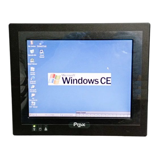
Page 9: Case Illustration
Chapter 1 Introduction 1-2. CASE ILLUSTRATION ′ Page: 1-3 PPC-7500F USER S MANUAL... -
Page 10: System Specification
Embedded in Intel ICH4 South Bridge BIOS : PhoenixAward PnP BIOS 4Mbytes with VGA BIOS KEYBOARD CONNECTOR : Mini DIN connector. Supports PS/2 Keyboard. MOUSE CONNECTOR : Mini DIN connector. Supports PS/2 Mouse. BUS SUPPORT : One PCI-104 ′ Page: 1-4 PPC-7500F USER S MANUAL... - Page 11 USB CONNECTOR : 2 USB ports on rear panel. Internal USB ports use 2.0 pitch box-header for connection. All USB ports support USB 2.0 standard. SOUND : ALC202A. AC’ 97 Codec. Interface: Line_IN, Line_OUT, MIC_IN ′ Page: 1-5 PPC-7500F USER S MANUAL...
-
Page 12: Lcd Panel
POWER CONSUMPTION : According to the supplier’s LCD specification. VIEWING ANGLE : According to the supplier’s LCD specification. RESPONSE TIME : According to the supplier’s LCD specification. COLOR : According to the supplier’s LCD specification. ′ Page: 1-6 PPC-7500F USER S MANUAL... -
Page 13: Touch Screen
TOUCH SCREEN : ACCU Vendor Type Resistive 500g (30 ㎝ , 30 Sec) Static Load Hardness Transparency Write Life 10,000,000 Times Knock Life 35,000,000 Times Chattering Time 10 ms Input Voltage Wire 5 Wire ′ Page: 1-7 PPC-7500F USER S MANUAL... - Page 14 1x Slim HDD 1x Compact Flash Type-II Slot (IDE, On Board) CONSTRUCTION : Electo Galvanized steel chassis. Aluminium front bezel. DIMENSIONS : 280mm x 232mm x 80mm (11.02” x 9.13” x 3.15”) NET WEIGHT : ′ Page: 1-8 PPC-7500F USER S MANUAL...
-
Page 15: Safety And Notification
16V~30V, otherwise the system may be damaged. 2. Environmental Conditions a. Place your PPC-7500F on a sturdy, level surface. Be sure to allow enough room on each side to have easy access. b. Avoid extremely hot or cold places to install your PPC. -
Page 16: Chapter 2 System Configuration
CHAPTER SYSTEM CONFIGURATION Helpful information that describes the jumper & connector settings, and component locations. Section includes: Jumper & Connector Quick Reference Table Component Locations Configuration and Jumper settings Connector Pin Assignments Page 2-1... -
Page 17: Jumper & Connector Quick Reference Table
IDE Power Module ……………………………………. POWER1 Compact Flash Connector ……………………………… PC104+ Connector ……………………………………… PC104PLUS1 CPU Fan Connector ……………………………………. JCFAN1 System Fan Connector …………………………………. JSFAN1 Serial ATA Connector …………………………………. SATA1 Reset & Speaker Connector ………………………….. Page: 2-2 ’ PPC-7500F USER S MANUAL... -
Page 18: Component Locations
Chapter 2 Hardware Configuration 2-2. COMPONENT LOCATIONS PPC-7500F Connector, Jumper and Component locations Page: 2-3 ’ PPC-7500F USER S MANUAL... -
Page 19: How To Set The Jumpers
PIN1 & PIN2 to create one setting and shorting. You can either connect PIN2 & PIN3 to create another setting. The same jumper diagrams are applied all through this manual. The figure below shows what the manual diagrams look and what they represent. Page: 2-4 ’ PPC-7500F USER S MANUAL... - Page 20 Chapter 2 Hardware Configuration JUMPER DIAGRAMS JUMPER SETTINGS Page: 2-5 ’ PPC-7500F USER S MANUAL...
- Page 21 Chapter 2 Hardware Configuration PPC-7500F Jumper Illustration Page: 2-6 ’ PPC-7500F USER S MANUAL...
-
Page 22: Com 1 Ri & Voltage Selection
Chapter 2 Hardware Configuration 2-4. COM 1 RI & VOLTAGE SELECTION JP6 : COM1 RI & Voltage Selection The selections are as follows: JUMPER SETTING JUMPER SELECTION (Pin Closed) ILLUSTRATION (default) COM1 Page: 2-7 ’ PPC-7500F USER S MANUAL... -
Page 23: Com 2 Ri & Voltage Selection
Chapter 2 Hardware Configuration 2-5. COM 2 RI & VOLTAGE SELECTION JP7 : COM2 RI & Voltage Selection The selections are as follows: JUMPER SETTING JUMPER SELECTION (Pin Closed) ILLUSTRATION (default) COM2 Page: 2-8 ’ PPC-7500F USER S MANUAL... -
Page 24: Com 3 Ri & Voltage Selection
Chapter 2 Hardware Configuration 2-6. COM 3 RI & VOLTAGE SELECTION JP9 : COM3 RI & Voltage Selection The selections are as follows: JUMPER SETTING JUMPER SELECTION (Pin Closed) ILLUSTRATION (default) COM3 Page: 2-9 ’ PPC-7500F USER S MANUAL... -
Page 25: Com 4 Ri & Voltage Selection
Chapter 2 Hardware Configuration 2-7. COM 4 RI & VOLTAGE SELECTION JP8 : COM4 RI & Voltage Selection The selections are as follows: JUMPER SETTING JUMPER SELECTION (Pin Closed) ILLUSTRATION (default) COM4 Page: 2-10 ’ PPC-7500F USER S MANUAL... -
Page 26: Rs232/422/485 (Com2) Selection
COM2 is selectable for RS-232, 422, 485 function. The jumper settings are as follows : COM 2 JUMPER SETTING JUMPER ILLUSTRATION FUNCTION (pin closed) RS-232 Open (default) 1-2, 3-4, 9-10 RS-422 1-2, 5-6, 7-8 RS-485 Page: 2-11 ’ PPC-7500F USER S MANUAL... -
Page 27: Brightness Voltage Selection
Chapter 2 Hardware Configuration 2-9. BRIGHTNESS VOLTAGE SELECTION JP1: Brightness Voltage Selection The selections are as follows : JUMPER SETTING JUMPER SELECTION (Pin Closed) ILLUSTRATION (default) 2.5V Page: 2-12 ’ PPC-7500F USER S MANUAL... -
Page 28: Lvds Voltage Selection
Chapter 2 Hardware Configuration 2-10. LVDS VOLTAGE SELECTION JP12: LVDS Voltage Selection The selections are as follows : JUMPER SETTING JUMPER SELECTION (Pin Closed) ILLUSTRATION VCC 3.3 1-3, 2-4 VCC 5 3-5, 4-6 Page: 2-13 ’ PPC-7500F USER S MANUAL... -
Page 29: Lvds Panel Resolution Selection
JP10 : LVDS Panel Resolution Selection. The selections are as follows: JUMPER JUMPER SETTING FUNCTION ILLUSTRATION (pin closed) 640 x 480 800 x 600 (10.4”) (default) 1024 x 768 (15”) 1280 x 1024 Page: 2-14 ’ PPC-7500F USER S MANUAL... -
Page 30: Clear Cmos Selection
To clear CMOS data, user must power-off the computer and set the jumper to “Clear CMOS” as illustrated above. After five to six seconds, set the jumper back to “Normal” and power-on the computer. Page: 2-15 ’ PPC-7500F USER S MANUAL... - Page 31 Interrupt, is used for serious conditions that demand the processor’s immediate attention, it cannot be ignored by the system unless it is shut off specifically. To clear NMI command, user should short the “Clear Watchdog” pin via push button. Page: 2-16 ’ PPC-7500F USER S MANUAL...
-
Page 32: Cpu_Vcca Voltage Selection
Chapter 2 Hardware Configuration 2-14. CPU_VCCA VOLTAGE SELECTION JP5: CPU_VCCA Voltage Selection The selections are as follows : JUMPER SETTING JUMPER SELECTION (Pin Closed) ILLUSTRATION VCCA 1.8V VCCA 1.5V *** Manufacturing Default: VCCA 1.8V. Page: 2-17 ’ PPC-7500F USER S MANUAL... -
Page 33: Cpu Frequency Selection
Chapter 2 Hardware Configuration 2-15. CPU FREQUENCY SELECTION JP3: CPU Frequency Selection The selections are as follows : JUMPER SETTING JUMPER SELECTION (Pin Closed) ILLUSTRATION 100 MHz *** Manufacturing Default: 100MHz. Page: 2-18 ’ PPC-7500F USER S MANUAL... -
Page 34: Com Port Connector
ASSIGNMENT DCD1 DTR1 COM1 DSR1 RTS1 CTS1 COM2 : COM2 Connector The COM2 Connector assignments are as follows : ASSIGNMENT RS-232 RS-422 RS-485 DCD2 COM2 DTR2 DSR2 RTS- RTS2 RTS+ CTS2 CTS+ CTS- Page: 2-19 ’ PPC-7500F USER S MANUAL... - Page 35 The pin assignments are as follows : ASSIGNMENT DCD4 DTR4 DSR4 RTS4 CTS4 All COM port’s pin 9 is selectable for RI, +5V or +12V. For more information, please refer to our “2-5 COM RI and Voltage Selection”. Page: 2-20 ’ PPC-7500F USER S MANUAL...
-
Page 36: Vga Connector
Chapter 2 Hardware Configuration 2-17. VGA CONNECTOR VGA1 : VGA Connector The pin assignments are as follows: ASSIGNMENT GREEN BLUE VGA DDC DATA HSYNC VSYNC VGA DDC CLK Page: 2-21 ’ PPC-7500F USER S MANUAL... -
Page 37: Lvds Connector
Chapter 2 Hardware Configuration 2-18. LVDS CONNECTOR LVDS1 : LVDS Connector The pin assignments are as follows : ASSIGNMENT ASSIGNMENT LVDS_VCC LVDS_VCC LVDS_VCC Page: 2-22 ’ PPC-7500F USER S MANUAL... -
Page 38: Power Connector
Chapter 2 Hardware Configuration 2-19. POWER CONNECTOR JATX1: Power Connector The pin assignments are as follows : ASSIGNMENT 5VSB PS_ON -12V Page: 2-23 ’ PPC-7500F USER S MANUAL... -
Page 39: Hard Disk Drive Connector
ASSIGNMENT ASSIGNMENT IDERSTJ PDD7 PDD8 PDD6 PDD5 PDD10 PDD4 PDD11 PDD3 PDD12 PDD2 PDD13 PDD1 PDD14 PDD0 PDD15 DDREQA DIOWAJ DIORAJ HDRDYA PULL LOW DDACKAJ IDE_IRQ14 PDA1 PD_80P PDA0 PDA2 PDCSJ1 PDCSJ3 HDLEDJ1 Page: 2-24 ’ PPC-7500F USER S MANUAL... -
Page 40: Printer Connector
As to link the Printer to the card, you need a cable to connect both DB25 connector and parallel port. The pin assignments are as follows : ASSIGNMENT ASSIGNMENT STROBE AFDJ PPD0 ERRORJ PPD1 INITJ PPD2 SLINJ PPD3 PPD4 PPD5 PPD6 PPD7 ACKJ BUSY SLCT Page: 2-25 ’ PPC-7500F USER S MANUAL... -
Page 41: Lan Connector
The pin assignment is as follows : ASSIGNMENT MDI_0P MDI_0N MDI_1P MDI_2P MDI_2N MDI_1N MDI_3P MDI_3N 2-23. LAN LED CONNECTOR LANLED1 : LAN LED Connector The pin assignment is as follows : ASSIGNMENT LED100 CONTROL LED1000 Page: 2-26 ’ PPC-7500F USER S MANUAL... -
Page 42: Keyboard Connector
The pin assignments are as follows : ASSIGNMENT KB DATA 5VSB KB CLK 2-25. PS/2 MOUSE CONNECTOR MS1 : PS/2 Mouse Connector The pin assignments are as follows : ASSIGNMENT MS DATA 5VSB MS CLK Page: 2-27 ’ PPC-7500F USER S MANUAL... -
Page 43: Hdd Led Connector
2-27. POWER BUTTON JPW1 : Power Button The pin assignments are as follows: ASSIGNMENT PWR_BN1 PWR_BN2 2-28. POWER LED CONNECTOR PWLED1: Power LED Connector. The pin assignments are as follows : ASSIGNMENT PW_LED+ Page: 2-28 ’ PPC-7500F USER S MANUAL... -
Page 44: Universal Serial Bus Connector
2-29. UNIVERSAL SERIAL BUS CONNECTOR USB1: Universal Serial Bus Connector. The pin assignments are as follows : ASSIGNMENT 5V_USB0 USB0N USB0P USB2: Universal Serial Bus Connector. The pin assignments are as follows : ASSIGNMENT 5V_USB1 USB1N USB1P Page: 2-29 ’ PPC-7500F USER S MANUAL... - Page 45 The pin assignments are as follows : ASSIGNMENT 5V_USB2 USB2N USB2P 5V_USB3 USB3N USB3P USB4 : Universal Serial Bus Connector. The pin assignments are as follows : ASSIGNMENT 5V_USB4 USB4N USB4P 5V_USB5 USB5N USB5P Page: 2-30 ’ PPC-7500F USER S MANUAL...
-
Page 46: Memory Installation
DRAM BANK CONFIGURATION DIMM 1 TOTAL MEMORY 128M 128MB 256M 256MB 512M 512MB 2-31. INVERTER CONNECTOR JINV1: Inverter Connector. The pin assignments are as follows : ASSIGNMENT VCC12 BRCTR ENVEE (Inverter backlight On/Off control signal) Page: 2-31 ’ PPC-7500F USER S MANUAL... -
Page 47: Power Module
Chapter 2 Hardware Configuration 2-32. POWER MODULE POWER1 : Power Module. The pin assignments are as follows : ASSIGNMENT ASSIGNMENT 5VSB 5VSB 5VSB PS-ON -12V +12V -12V +12V -12V +12V Page: 2-32 ’ PPC-7500F USER S MANUAL... -
Page 48: Compact Flash Connector
Chapter 2 Hardware Configuration 2-33. COMPACT FLASH CONNECTOR CF1 : Compact Flash Connector. The pin assignments are as follows : ASSIGNMENT ASSIGNMENT CSJ1 CSJ3 SDIORDJ SDIOWRJ IRQ15 -CSEL RESETJ IORDY ACKJ CF_LEDJ -PDIAG Page: 2-33 ’ PPC-7500F USER S MANUAL... - Page 49 D24 GNTJ0 GNTJ1 B25 NC GNTJ2 D25 GND B26 PCLK1 D26 PCLK2 PCLK3 B27 +5V PCLK4 D27 GND B28 INTDJ D28 RSTJ +12V B29 INTAJ INTBJ D29 INTCJ -12V B30 NC D30 GND Page: 2-34 ’ PPC-7500F USER S MANUAL...
-
Page 50: Cpu Fan Connector
JCFAN1 : CPU Fan Connector ASSIGNMENT GROUND FAN_VCC12 FAN_SPEED OUT FAN_PWM 2-36. SYSTEM FAN CONNECTOR JSFAN1 : System FAN Connector ASSIGNMENT VCC12 2-37. SERIAL ATA CONNECTOR SATA1 : Serial ATA Connector ASSIGNMENT SATAHDR_TXP0 SATAHDR_TXN0 SATAHDR_RXN0 SATAHDR_RXP0 Page: 2-35 ’ PPC-7500F USER S MANUAL... -
Page 51: Reset & Speaker Connector
Chapter 2 Hardware Configuration 2-38. RESET & SPEAKER CONNECTOR J1 : Reset and Speaker Connector ASSIGNMENT SPK_VCC RST_SW Page: 2-36 ’ PPC-7500F USER S MANUAL... - Page 52 CHAPTER SOFTWARE UTILITIES This chapter comprises the detailed information of VGA driver, LAN driver, and sound driver, VIA Chipset Software Installation Utility, touch screen driver, USB 2.0 driver and Flash BIOS update. It also describes how to install the watchdog timer configuration. Section includes: Introduction VGA Driver Utility...
- Page 53 Chapter 3 Software Configuration 3-1. INTRODUCTION Enclosed with our PPC-7500F package is our driver utility, which may comes in a form of a CD ROM disc or floppy diskettes. For CD ROM disc user, you will only need some of the files contained in the CD ROM disc,...
-
Page 54: Vga Driver Utility
Chapter 3 Software Configuration 3-2. VGA DRIVER UTILITY The VGA interface embedded with our PPC-7500F can support a wide range of display. You can display CRT, LVDS simultaneously with the same mode. 3-3-1. Installation of VGA Driver: To install the VGA Driver, simply follow the following steps: (1). -
Page 55: Flash Bios Update
Chapter 3 Software Configuration 3-3. FLASH BIOS UPDATE 3-3-1. Introduction Users of PPC-7500F can use the program “Awdflash.exe” contained in the Utility Disk for system BIOS update. 3-3-2. Installation of system BIOS 1. Copy “Awdflash.exe” from Driver Disk to Drive C. - Page 56 File Name to Program: 7500xxxx.bin Verifying Flash Memory – 7FFFF OK Write OK No Update Write Fail F1: Reset F10: Exit Please reset or power off the system, then the Flash BIOS is fully implemented. ′ Page:3-5 PPC-7500F USER S MANUAL...
-
Page 57: Lan Driver Utility
Chapter 3 Software Configuration 3-4. LAN DRIVER UTILITY 3-4-1. Introduction The PPC-7500F Panel PC is enhanced with LAN function that can support various network adapters. Installation programs for LAN drivers are listed as follows: For more details on Installation procedure, please refer to Readme.txt file found on LAN DRIVER UTILITY. -
Page 58: Sound Driver Utility
“D:\Sound\pathname” refers to the full path to the source files. 3. Click on the OK button or press the ENTER key. 4. Click on the “Next” and OK prompts as they appear. 5. Reboot the system to complete the driver installation. ′ Page:3-7 PPC-7500F USER S MANUAL... - Page 59 3. Click Setup.exe file for utility installation. 4. Follow the instructions on the screen to complete the installation. 5. Once installation is completed, shut down the system and restart in order for the changes to take effect. ′ Page:3-8 PPC-7500F USER S MANUAL...
- Page 60 5. Double Click “USB Root Hub”. 6. Select “Driver”. 7. Click “Install” to install the driver. 8. Follow the instructions on the screen to complete the installation. 9. Click “Finish” after the driver installation is complete. ′ Page:3-9 PPC-7500F USER S MANUAL...
-
Page 61: Serial Ata Driver Utility
Select “Hardware” and click “Device Manager” button. Double click “RAID Controller”. Select “Driver”. Click “Si3112r” to install the driver. Follow the instructions on the screen to complete the installation. Click “Finish” after the driver installation is complete. ′ Page:3-10 PPC-7500F USER S MANUAL... -
Page 62: Watchdog Timer Configuration
WDT_VAL to any other non-zero value will cause the WDT to reload and begin counting down from the value loaded. Setting the Register located on I/O address 0x867h and 0x868h as 00h to finish timer configuration. Example Program ′ Page:3-11 PPC-7500F USER S MANUAL... - Page 63 CHAPTER AWARD BIOS SETUP This chapter shows how to set up the Award BIOS. Section includes: Introduction Entering Setup The Standard CMOS Features The Advanced BIOS Features The Advanced Chipset Features Integrated Peripherals Power Management Setup PNP/PCI Configuration PC Health Status Frequency Control Load Fail-Safe Defaults Load Optimized Defaults...
- Page 64 4-1. INTRODUCTION This chapter will show you the function of the BIOS in managing the features of your system. The PPC-7500F Panel PC is equipped with the BIOS for system chipset from Award Software Inc. This page briefly explains the function of the BIOS in managing the special features of your system.
-
Page 65: Entering Setup
You may use the cursor the up/down keys to highlight the individual menu items. As you highlight each item, a brief description of the highlighted selection will appear at the bottom of the screen. ′ Page: 4-3 PPC-7500F USER S MANUAL... -
Page 66: The Standard Cmos Features
< Hour >, < Minute >, and < Second >. Use 24 hour clock format, i.e., for PM numbers, add 12 to the hour. For example: 4: 30 P.M. You should enter the time as 16:30:00. ′ Page: 4-4 PPC-7500F USER S MANUAL... - Page 67 Auto: The BIOS automatically determines the optimal mode. Normal: Maximum number of cylinders, heads, sectors supported are 1024, 16 and 63. Large: For drives that do not support LBA and have more than 1024 cylinders. ′ Page: 4-5 PPC-7500F USER S MANUAL...
- Page 68 BASE MEMORY: Displays the amount of conventional memory detected during boot up. EXTENDED MEMORY: Displays the amount of extended memory detected during boot up. TOTAL MEMORY: Displays the total memory available in the system. ′ Page: 4-6 PPC-7500F USER S MANUAL...
-
Page 69: Chapter 4 Award Bios Setup
1024 65535 1023 1024 65535 1023 1024 65535 1023 1024 65535 1023 1024 65535 1023 65535 1023 65535 1024 65535 1023 1024 65535 1023 65535 65535 65335 AUTO Award Hard Disk Type Table ′ Page: 4-7 PPC-7500F USER S MANUAL... -
Page 70: The Advanced Bios Features
If this function is enabled and someone attempt to write data into this area, BIOS will show a warning message on screen and alarm beep. CPU L1 & L2 CACHE: This item allows you to enable L1 & L2 cache. ′ Page: 4-8 PPC-7500F USER S MANUAL... - Page 71 This item sets the number of times a second to repeat a key stroke when you hold the key down. TYPEMATIC DELAY (MSEC): The item sets the delay time after the key is held down before it begins to repeat the keystroke. ′ Page: 4-9 PPC-7500F USER S MANUAL...
- Page 72 Do not type anything and just press <Enter>, it will disable security. Once the security is disabled, the system will boot and you can enter Setup freely. ′ Page: 4-10 PPC-7500F USER S MANUAL...
-
Page 73: Advanced Chipset Features
The default settings have been chosen because they provide the best opera- ting conditions for the system. The only time you might consider making any changes would be if you discovered that data was being lost while using your system. ′ Page: 4-11 PPC-7500F USER S MANUAL... - Page 74 Select Enabled allows caching of the video BIOS, resulting in better system performance. However, if any program writes to this memory area, a system error may result. On-Chip VGA To Enable/Disable the onboard display chip. Boot Display To select the boot-up display type. ′ Page: 4-12 PPC-7500F USER S MANUAL...
-
Page 75: Integrated Peripherals
If bios setup menu item supports USB device boot, it will cause Win9x detects the same storages twice when the system is rebooted, and USB HDD will fail. Note: this cause just happen under Win9x, the phenomenon is a limitation. ′ Page: 4-13 PPC-7500F USER S MANUAL... - Page 76 Ultra DMA/33 implementation is possible only if your IDE hard drive supports it and the operating environment includes a DMA driver (Windows 95 OSR2 or a third-party IDE bus master driver). If you hard drive and your system software both support Ultra DMA/33, ′ Page: 4-14 PPC-7500F USER S MANUAL...
- Page 77 Select Enabled if your system contains a Universal Serial Bus (USB) controller and you have a USB Mouse. Audio: AC97 This item allows you to enable/disable to support AC97 Audio. 5. PCI Option ROM Support To Enabled/Disable the LAN PXE ROM ′ Page: 4-15 PPC-7500F USER S MANUAL...
- Page 78 Select Normal, Compatible, or SPP unless you are certain your hardware and software both support one of the other available modes. 5. ECP Mode Use DMA Select a DMA channel for the parallel port for use during ECP mode. ′ Page: 4-16 PPC-7500F USER S MANUAL...
-
Page 79: Power Management Setup
Power Management Setup Screen The “Power Management Setup” allows the user to configure the system to the most effectively save energy while operating in a manner consistent with your own style of computer use. ′ Page: 4-17 PPC-7500F USER S MANUAL... - Page 80 An input signal from PME on the PCI card awakens the system from a soft off state. RESUME BY ALARM: When Enabled, your can set the date and time at which the RTC (real-time clock) alarm awakens the system from Suspend mode. ′ Page: 4-18 PPC-7500F USER S MANUAL...
-
Page 81: Pnp/Pci Configuration
RESOURCE CONTROLLED BY: The Award Plug and Play Bios can automatically configure all of the booth and Plug and Play-compatible devices. However, this capability means ′ Page: 4-19 PPC-7500F USER S MANUAL... - Page 82 F5: Previous Values F6:Fail-Safe Defaults F7:Optimized Defaults Descriptions on each item above are as follows: IRQ-n Assigned to: You may assign each system interrupt a type, depending on the type of device using the interrupt. ′ Page: 4-20 PPC-7500F USER S MANUAL...
-
Page 83: Pc Health Status
Windows 98 ACPI mode. CURRENT CPU TEMPERATURE: This item shows you the current CPU temperature. CURRENT SYSTEM FAN SPEED: This item shows you the current System FAN speed. +2.5/Vcore/Vcc3/VBAT/5V/12V Show you the voltage of +2.5/Vcore/Vcc3/VBAT/5V/12V ′ Page: 4-21 PPC-7500F USER S MANUAL... -
Page 84: Frequency Control
Enabling pulse spectrum spread modulation changes the extreme values from spikes to flat curves, thus reducing EMI. This benefit may in some cases be outweighed by problems with timing- critical devices such as a clock-sensitive SCSI device. ′ Page: 4-22 PPC-7500F USER S MANUAL... -
Page 85: Load Fail-Safe Defaults
When you press <Enter> on this category, you get a confirmation dialog box with a message similar to the following: Load Optimized Defaults ( Y/N ) ? N Pressing "Y" loads the default values that are factory setting for optimal performance system operations. ′ Page: 4-23 PPC-7500F USER S MANUAL... -
Page 86: Password Setting
PASSWORD DISABLED!!! Press any key to continue... Press the < Enter > key again and the password will be disabled. Once the password is disabled, you can enter Setup freely. ′ Page: 4-24 PPC-7500F USER S MANUAL... -
Page 87: Save & Exit Setup
You may always call up the setup program at any time to adjust any of the individual items by pressing the <Del> key during boot up. ′ Page: 4-25 PPC-7500F USER S MANUAL... -
Page 88: Exit Without Saving
Set Supervisor Password ►Power Management word Quit Without Saving (Y/N)? N ►PnP/PCI Configura etup ►PC Health Status Saving Esc : Quit ↑↓→← : Select Item F10 : Save & Exit Setup Abandon all Datas ′ Page: 4-26 PPC-7500F USER S MANUAL... -
Page 89: Appendix A System Assembly
APPENDIX SYSTEM ASSEMBLY This appendix contain exploded diagram of the system. Section includes: Exploded Diagram for Hardware Assembly Exploded Diagram for Removing Hook Holder Exploded Diagram for Removing Back Cover Exploded Diagram for Cut-Out Dimension Exploded Diagram for Rubber Installation Exploded Diagram for Whole System Page: A-1... -
Page 90: Exploded Diagram For Hardware Assembly
Appendix A System Assembly EXPLODED DIAGRAM FOR HARDWARE ASSEMBLY ′ Page: A-2 PPC-7500F USER S MANUAL... -
Page 91: Exploded Diagram For Removing Hook Holder
Appendix A System Assembly EXPLODED DIAGRAM FOR REMOVING HOOK HOLDER ′ Page: A-3 PPC-7500F USER S MANUAL... -
Page 92: Exploded Diagram For Removing Back Cover
Appendix A System Assembly EXPLODED DIAGRAM FOR REMOVING BACK COVER ′ Page: A-4 PPC-7500F USER S MANUAL... -
Page 93: Exploded Diagram For Cut-Out Dimension
Appendix A System Assembly EXPLODED DIAGRAM FOR CUT-OUT DIMENSION ′ Page: A-5 PPC-7500F USER S MANUAL... -
Page 94: Exploded Diagram For Rubber Installation
2. Aligning the waterproof rubber by matching its 4 rubber pins to the 4 holes. 3. Pushing those pins into the holes, then firmly press the seal lip of waterproof rubber into the groove. ′ Page: A-6 PPC-7500F USER S MANUAL... -
Page 95: Exploded Diagram For Whole System
Appendix A System Assembly EXPLODED DIAGRAM FOR WHOLE SYSTEM ′ Page: A-7 PPC-7500F USER S MANUAL... - Page 96 APPENDIX TECHNICAL SUMMARY This section introduce you the maps concisely. Sections include: Block Diagram Interrupt Map RTC (Standard) RAM Bank Timer & DMA Channels Map I / O & Memory Map Page: B-1...
-
Page 97: Appendix B Technical Summary Block Diagram
Appendix B Technical Summary BLOCK DIAGRAM ′ Page: B-2 PPC-7500F USER S MANUAL... -
Page 98: Interrupt Map
Serial port 2 Serial port 1 Available Floppy Disk adapter Parallel port 1 RTC clock ACPI-Compliant System Serial port 3 Serial port 4 PS/2 Mouse Math coprocessor Hard Disk adapter Hard Disk adapter ′ Page: B-3 PPC-7500F USER S MANUAL... - Page 99 Second alarm Minutes Minutes alarm Hours Hours alarm Day of week Day of month Month Year Status register A Status register B Status register C Status register D 0Eh-7Fh 114 Bytes of User RAM ′ Page: B-4 PPC-7500F USER S MANUAL...
-
Page 100: Timer & Dma Channels Map
Timer Channel Map : Timer Channel Assignment System timer interrupt DRAM Refresh request Speaker tone generator DMA Channel Map : DMA Channel Assignment Available Available Floppy Disk adapter Available Cascade Available Available Available ′ Page: B-5 PPC-7500F USER S MANUAL... -
Page 101: I/O & Memory Map
RTC Controller NMI & RTC controller RTC RTC Controller RTC Controller RTC Controller NMI & RTC controller RTC RTC Controller RTC Controller RTC Controller NMI & RTC controller RTC RTC Controller RTC Controller ′ Page: B-6 PPC-7500F USER S MANUAL... - Page 102 2. Only if IDE Standard I/O space is enabled for Secondary Drive. Otherwise, the target is PCI. 3. If POS_DEC_EN bit is enabled, reads from F0h will not be decoded by the ICH2. If POS_DEC_EN is not enabled, reads from F0h will forward to LPC. ′ Page: B-7 PPC-7500F USER S MANUAL...
- Page 103 Bit 0 in FWH Decode Enable 2 FF00 0000h-FF0F FFFFh Register is set Anywhere in 4GB range D110 LAN Controller Enable via BAR in Device 29:Function 0 (D110 LAN Controller) All Other None ′ Page: B-8 PPC-7500F USER S MANUAL...
Need help?
Do you have a question about the PPC-7500F and is the answer not in the manual?
Questions and answers