Table of Contents
Advertisement
Advertisement
Table of Contents
Troubleshooting

Related Manuals for CAS CUW Series


Summary of Contents for CAS CUW Series
-
Page 2: Notation Conventions
Notation Conventions This instruction manual uses the following notation conventions to indicate Safety Precautions and additional information. Indicates a potentially hazardous situation that may result in injury to personnel or equipment damage. Provides additional information needed to properly use the balance. Other conventions used in this manual include: Item Description... -
Page 3: Safety Precautions
Safety Precautions To ensure safe and proper operation of the balance, observe the following precautions. Do not use the balance in hazardous areas. This includes areas where the balance is expose to dust or flammable gases and liquids. Use the AC adapter specified by Shimadzu. To prevent electric shock, never disassemble the AC adapter. -
Page 4: Declaration Of Conformity
Declaration Of Conformity CAS Corporation declares that the following products: UW Series and UX Series Electronic Balances conform to the following directives. Directives EMC directive 89/336/EEC amended by 92/31/EEC, 93/68/EEC EN55022: 1994 / A1: 1995 / A2: 1997 (Class B) - Page 5 The controls implemented as a result of security related requirements are intended to result in trusted records. CAS CLASS-Balance Agent CAS provides a means for compliance with 21 CFR Part 11 with CAS CLASS-Balance Agent software, part of a comprehensive laboratory data management system, CAS CLASS Agent.
-
Page 6: Table Of Contents
Notation Conventions Safety Precautions ..........................11 1. Introduction ............12 2. Name and Function of Components 2.1 Components......................12 2.2 Key Panel and Operation...................14 2.3 Balance Display and Function ................15 ......................16 3. Specifications ......................17 4. Installation 4.1 Choosing the Installation Site................17 4.2 Unpacking and Delivery Inspection ..............19 4.3 Installation ......................22 4.4 Turning ON the Power..................27 4.5 Span Calibration....................28... - Page 7 .....................38 7. Menu Item Selection 7.1 What is the Menu?.....................38 7.2 Menu Map......................38 7.3 Menu Item Selection Procedure................39 7.4 Setting Numeric Values..................41 7.5 Related Useful Functions ..................42 7.5.1 Last Menu Recall...................42 7.5.2 Returning to the Default Settings (menu reset)........42 7.5.3 Menu Lock.....................43 ..................44 8.
- Page 8 ......................57 11. Environment 11.1 Overview ......................57 11.2 Stability and Response (Averaging)..............57 11.3 Stability Detection Settings ................58 11.3.1 What is Stability Detection?..............58 11.3.2 Stability Detection Band..............59 11.3.3 Timing of Stability Mark Illumination and Linked Operation..60 11.4 Tracking......................60 .........................61 12. Units 12.1 Unit Display Set-up ..................61 12.2 Percentage (%) Conversion................62 ................63 13.
- Page 9 .............87 15. Connecting Peripheral Instruments 15.1 Electronic Printer .....................87 15.2 Personal Computer - RS-232C -..............88 15.2.1 Connecting the Cable ................88 15.2.2 Data Format ..................89 15.2.3 Using Command Codes..............91 15.2.4 Multi-Connection Mode ..............96 15.3 Communication Setting...................99 15.3.1 Overview....................99 15.3.2 Handshaking ..................99 15.3.3 Format ....................100 15.3.4 Communication Speed..............100 15.3.5 Parity / Bit Length ................100...
-
Page 10: Introduction
1. Introduction CAS UW/UX series of toploading balances are a product of our 80 year history of developing and manufacturing weighing instruments. CAS UW/UX series of toploading balances utilize the patented CAS UniBloc sensor, introduced in 1989, to achieve high performance, fast response, and durability. -
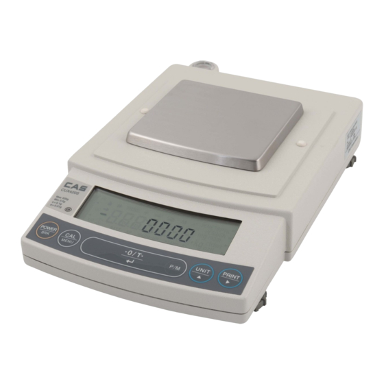
Page 11: Name And Function Of Components
2. Name and Function of Components 2.1 Components a. Large pan model b. Small pan model (minimum display 0.01g) - Page 12 c. Small pan model (minimum display 0.001g, windbreak standard) a, b, c. common...
-
Page 13: Key Panel And Operation
2.2 Key Panel and Operation Functions of the keys During Weighing Press Once and Release Press and Hold for About 3 Seconds Switches between the operation and standby Exits the application function and returns to [POWER] modes. the mass display. Enters span calibration or menu item Displays the last menu item that was set. -
Page 14: Balance Display And Function
2.3 Balance Display and Function Display Name Description Indicates that the weighed value is stable. (*1) In menu item selection, Stability mark indicates currently selected item. Tare symbol Indicates that a Pretare value has been set. Illuminates during span calibration. In menu selection, indicates setting Weight symbol related to calibration. -
Page 15: Specifications
3. Specifications UW Series Model UW220H UW420H UW620H UW2200H UW4200H UW6200H UW420S UW820S UW4200S UW8200S Capacity 220g 420g 620g 2200g 4200g 6200g 420g 820g 4200g 8200g Minimum display 0.001g 0.001g 0.001g 0.01g 0.01g 0.01g 0.01g 0.01g 0.1g 0.1g Calibration range 100- 100- 100-... -
Page 16: Installation
4. Installation 4.1 Choosing the Installation Site (1) Power supply Select an installation site that is near a power source to ensure that the attached AC adapter is used properly. If this is not possible, an optional battery pack is available as a special accessory. - Page 17 Corrosive or flammable gasses Dust, wind, electromagnetic waves, or magnetic fields Large capacity balances should be installed on a sturdy floor and table that can support the total load of the balance AND object to be weighed.
-
Page 18: Unpacking And Delivery Inspection
4.2 Unpacking and Delivery Inspection Unpack and remove all the items from the delivery box. Check if all the listed items are present and nothing has been damaged. Contact your local distributor in case of damaged or missing items. Standard packed item and quantity b. - Page 19 a. Large pan model b. Small pan model (minimum display 0.01g)
- Page 20 c. Small pan model (minimum display 0.001g)
-
Page 21: Installation
4.3 Installation (Start at step 3 when installing a UX series balance. Prepare a plus (+) screw driver for a UW series balance.) . Place the balance main body upside down. (UW only) Do not operate step 2 with the balance placed on its side. - Page 22 . This balance has three level screws (adjustable feet) at the right front, left front and right rear corners. Turning a level screw clock-wise stretches the leg to raise the balance body there. Turning anticlockwise withdraws the leg and lowers the balance body. The level indicator locates at left rear.
- Page 23 . Install the pan. With small pan model with minimum display of 0.001g, the standard windbreak is also installed here. a. Large pan model Insert the four pan supporter caps into the holes in the top of the balance. Place the pan gently on pan supporter caps.
- Page 24 (2) Fit windbreak main on top of the balance main body, and fasten it with two fixing knobs. (3) Insert the four pan supporter caps into the holes in the top of the balance. Place the pan on them. Positioners on the pan must fit pan supporter caps.
- Page 25 . If you use protective in-use cover, peel off the paper to expose the adhesive on it, then fit it on the display and key part. Press the adhesive parts gently.
-
Page 26: Turning On The Power
4.4 Turning ON the Power . Insert the plug of the AC adapter into the DC IN connector on the rear of the balance. . Insert the AC adapter into the power source. The balance self-check is activated and the following messages are displayed in the order indicated. -
Page 27: Span Calibration
4.5 Span Calibration It is necessary to calibrate the balance after it is moved. Verify that the balance is stable before performing the span calibration. To achieve a very stable state, ensure that the balance has been turned on with the gram-display for at least one hour, that the temperature is constant, that there are no breezes or vibrations and that the balance is in an area isolated from the normal traffic flow. - Page 28 UX series [Span Calibration Using External Weights] . Verify that the balance is in gram-display and unload the sample from the pan. (Example) . Press the [CAL] key once. E-CAL” is displayed. . Press the [O/T] key. The value of the correct calibration weight to be loaded is displayed and blinks.
-
Page 29: Basic Operation
5. Basic Operation 5.1 Weighing . If a weighing vessel (tare) is used, place it on the pan and wait for the stability mark to illuminate. . Press the [O/T] key to zero the display. (This operation is called “taring”.) . -
Page 30: Changing The Unit Display
5.2 Changing the Unit Display Every time the [UNIT] key is pressed, the unit display changes sequentially among those set-up in 12.1 Unit Display Set-up. Gram, %, and PCS have been set-up before delivery. Before a unit can be displayed it must be registered in 12.1 Unit Display Set-up. -
Page 31: Windowsdirect Function
6.2 Set Up WindowsDirect Simple settings are made for the balance and the computer. Connection is by RS-232C cable (15.2.1) specified by CAS. If bi-directional communication software is used: WindowsDirect function should be turned off. Set up the optimal communication parameters for the software according to “15.3 Communication setting”. -
Page 32: Cable Connection
6.2.2 Cable Connection . Verify the balance display is “STAND-BY”. . Turn off the computer and remove power from the balance. . Connect the RS-232C cable to the balance. . Connect the RS-232C cable to the computer. 6.2.3 Setting Up the Computer (leave the balance unplugged) . - Page 33 . Select the serial port corresponding to the RS- 232C port of your personal computer. (Serial port: any one of COM1 to 4. Usually, COM1) . Select a “Baud rate” of 300.. . Click “OK”. . Click “Apply” and wait. .
-
Page 34: Start And Checking Operation
6.2.4 Start and Checking Operation . Start Windows®. . After Windows® has completely started, connect power cord from the AC adapter to the balance, when “oFF” is displayed, press the [POWER] key. The mass display appears. Turning ON the balance before Windows®* is completely activated may cause incorrect operation. -
Page 35: Troubleshooting
6.3 Troubleshooting This function may not operate on a computer on which a normal U.S. version of Microsoft Windows®* does not operate. Some types of personal computers may not be able to use this function or some features may be limited. Shimadzu does not guarantee that this function can be used on all computers without any problems currently or in the future. - Page 36 When the WindowsDirect Function Intermittently Malfunctions: Use a communication speed of 300bps. Depending on the processing ability of the computer, this function may operate incorrectly if communication speed is too high. Send the next data only after the current one is displayed on the screen. Depending on the processing ability of the PC, this function may operate incorrectly if the interval of data transmission is too short.
-
Page 37: Menu Item Selection
7. Menu Item Selection 7.1 What is the Menu? The UW/UX series balance has many functions that can be selected to meet the requirements of the user. Menu Item selection is used to program these functions. 7.2 Menu Map The menu of the UW/UX balance consists of seven groups and four levels. The Menu Map shows the structure clearly with menu item numbers to help access the desired function. -
Page 38: Menu Item Selection Procedure
7.3 Menu Item Selection Procedure This instruction manual identifies each menu item by a number. For example, the menu items of “Stability Detection Band ” of “11. Environment” are 27 through 33 . Find the function to be programmed in the Menu Map, referring to the item number in square, No. - Page 39 Important Note on Menu Item Selection Even the desired menu item is reached and displayed, it is not yet set unless Stability mark ( ) is illuminated with it. Do not fail to press [O/T] key to put Stability mark before returning to the mass display. .
-
Page 40: Setting Numeric Values
7.4 Setting Numeric Values Some of UW/UX series balance menu items require numeric value setting. For example, external calibration weight input, thresholds for checkweighing, and reference density in pecific gravity measurements (see 10.2, 10.3, 13.1, 13.5, 13.8, 14.1, 14.2, 14.4 for detail of each item.) The values can be set using the balance keys. -
Page 41: Related Useful Functions
7.5 Related Useful Functions 7.5.1 Last Menu Recall This function is convenient when an application requires frequent changes to a specific menu item. During mass display or menu selection, press and hold the [CAL] key for approximately three seconds. The last menu item that was changed or set is displayed. 7.5.2 Returning to the Default Settings (menu reset) The procedure below describes how to reset the menu and return to the default settings. -
Page 42: Menu Lock
7.5.3 Menu Lock The “Menu Lock” function locks the menu item selection to protect the current settings from undesired alterations. Menu Lock can be activated or released only at the “oFF” display immediately after the balance is connected to the power. (How to lock the menu) . -
Page 43: Built-In Clock Set-Up
8. Built-in Clock Set-up The built-in clock has to be set up in advance if a calibration record is to be produced or Clock-CAL function is to be used. 8.1 Date . Select menu item 63 and set the last two figures of the year, month and day, using the [UNIT] and [PRINT] keys. -
Page 44: Time
8.3 Time (Example) Select menu item 64 and set the time in the 24 hour system using the [UNIT] and [PRINT] keys, then press the [O/T] key. Example: 1:23 in the afternoon, is set as “13:23”. The moment the [O/T] key is pressed seconds are set to 00. 8.4 Setting Display During Stand-by Determine what is to be displayed during stand-by. -
Page 45: Display Selection
9. Display Selection 9.1 Bar graph display The relative amount of the load on the pan is displayed in the bar graph. This feature helps to prevent errors due to OL (overload) status. This is called Full Scale mode. This display can not be used with the Checkweighing or Target mode. -
Page 46: Calibration
10. Calibration 10.1 What is calibration? Calibration is required to accurately weigh items with an electronic balance. Calibration should be performed: When the location of the balance is changed, even within the same room. When the room temperature changes considerably. Periodically, according to the quality control plan of the user. -
Page 47: Calibration Execution
10.2 Calibration Execution Setting before shipment is as the following: UW series: Span calibration using the built-in weight UX series: Span calibration using external weights The type of calibration can be changed (See 10.3). Calibration will not be performed when the weight on the pan is not near zero, or the balance is not stable. -
Page 48: Calibration Check Using The Built-In Weight (Uw Series Only)
10.2.2 Calibration Check Using the Built-in Weight (UW Series Only) The shift from the last calibration is displayed using the built-in calibration weight, however, the balance is not adjusted. . Verify that the balance is in mass display and that the pan is empty. . -
Page 49: Span Calibration Using External Weights
10.2.3 Span Calibration Using External Weights The balance is adjusted using your external standard calibration weight(s). . Verify that the balance is in mass display and that the pan is empty. . Press the [CAL] key once. “E-CAL” is displayed. (If “E-CAL”... -
Page 50: Calibration Check Using External Weights
10.2.4 Calibration Check Using External Weights The shift from the last calibration is displayed using your external standard calibration weight(s), however, the balance is not adjusted. . Verify that the balance is in mass display and that the pan is empty. . -
Page 51: Calibration Setting
10.3 Calibration Setting 10.3.1 Selecting the Calibration Type Set the calibration type that will be used in Calibration Execution. To set up “Span calibration using the built-in weight”,(UW only) Select menu item 1 . To set up “Calibration check using the built-in weight”,(UW only) Select menu item 2 . To set up “Span calibration using external weights”, Select menu item 3 . -
Page 52: Clock-Cal Fully-Automatic Calibration (Uw Series Only)
10.3.3 Clock-CAL Fully-automatic Calibration (UW series only) Span calibration is performed automatically using the built-in calibration weight at up to 3 specific, pre-set times during each day. The user selects the times. This function is named Clock-CAL. It is possible to set up to three specific times for Clock-CAL (“tCALt1”, “tCALt2”, and “tCALt3”). -
Page 53: Pcal: Calibration Of The Built-In Weight (Uw Series Only)
10.3.4 PCAL: Calibration of the Built-in Weight (UW series only) PCAL is used to calibrate the built-in weight to a standard calibration weight that is correctly adjusted, traceable and/or certified. The PCAL procedure is password protected. The administrator should set this password (refer to 10.3.5). Use a correctly controlled, precise calibration weight for this procedure. -
Page 54: Pcal Password Setting (Uw Series Only)
To execute Clock-CAL, all of the following conditions must be satisfied at the set time. If these conditions are not satisfied within one minute, the automatic span calibration is not executed and that cycle is skipped. The balance must be in mass display or the standby mode. The balance must be stable. -
Page 55: For Glp/Gmp/Iso Conformance
10.4 For GLP/GMP/ISO Conformance These settings should be made by the administrator. 10.4.1 Calibration Report Setting Turns the calibration report function ON/OFF. Use this to generate and output a calibration report as for GLP, GMP, or ISO9000. An electronic printer (optional accessory) is required to print the report. -
Page 56: Environment
11. Environment 11.1 Overview Settings on the balance can be changed to compensate for the installation environment such as the degree of vibration or air movement or for the purpose of weighing a solid, liquid or powder. 11.2 Stability and Response (Averaging) It is possible to match the stability of the display and the degree of response with the requirements of specific applications or the installation environment. -
Page 57: Stability Detection Settings
While “Pouring” is selected as the Stability and Response setting, taring the container or zeroing the display cannot be made by pressing the rightmost part of [O/T] key. Press the center or the left part of [O/T] key for taring or zeroing. Select menu item 24 . -
Page 58: Stability Detection Band
Although stability detection settings are optimized at default, they can be changed as instructed in 11.3.2 and 11.3.3 depending on specific measurement requirements. Functions that use stability detection Auto Print (See 13.3), Auto Zero (See 13.4), Taring/Printing at Stability (See 13.6), Peak Hold (See 14.3), Auto-Memory and Zeroing (See 14.5), Animal Weighing (See 14.6), Formulation Mode (See 14.7). -
Page 59: Timing Of Stability Mark Illumination And Linked Operation
11.3.3 Timing of Stability Mark Illumination and Linked Operation This setting is effective on both stability mark illumination and function operations triggered by stability detection. Upon detection of stability, stability mark is illuminated. Also, the function operation linked to stability detection is triggered at the same timing as illumination of stability mark. This timing can be adjusted to three levels, although it is optimized at the default setting. -
Page 60: Units
12. Units 12.1 Unit Display Set-up The UW/UX series balance can display weighed results in various weighing units. . It is possible to display units other than “g”. Press the [UNIT] key in mass display to sequentially change the selected units. (Example) When menu item 58 (carat) has been selected. -
Page 61: Percentage (%) Conversion
12.2 Percentage (%) Conversion . Set the % unit with menu item 56 if it is not set up. The % unit is set before shipment. . Press the [UNIT] key several times in the mass display until the % unit is displayed. Setting the 100% reference . -
Page 62: Enhancing Productivity
13. Enhancing Productivity Functions that are useful mainly in production sites are described in this chapter. Only one of the functions in the menu group 4 (Refer to 7.3) ( 41 to 53) can be used at a time. When one of the functions in menu group 4 is to be used with a weighing unit other than gram, select the function from the gram-display first. -
Page 63: Checkweighing (Comparator) Display Type 1
13.1.1 Checkweighing (Comparator) Display Type 1 This is the best mode to determine pass or failure judgment based on the sample weight. Displays in use . Select menu map item 15 . . Set the upper threshold value, which corresponds to the upper triangle mark, with menu item 16 . -
Page 64: Target Mode
Upper threshold < Sample weight Lower threshold ≤ Sample weight ≤ Upper threshold Sample weight < Lower threshold The decimal point is invisible in each value setting display. Setting the value cannot be made in gram unit. Determine the number based on the minimum display of the balance. -
Page 65: Piece Counting (Pcs)
13.2 Piece Counting (PCS) . Set up the PCS with menu item 57 if it is not set. (The PCS unit is set before shipment.) . Press the [UNIT] key several times in the mass display until the PCS is displayed. . -
Page 66: Auto Print
13.3 Auto Print Auto Print function allows output of the data automatically without pressing the [PRINT] key for each sample. The “Auto-Print symbol is illuminated when the Auto Print function is activated. Six types of Auto Print are selectable. Print on loading: Select menu item 42 . Load the sample when the value displayed is within the Zero Range. - Page 67 During continuous output, the Communication symbol may appear to remain lit. If the transfer speed of the data output is slow, the display may become unstable. Increase the transfer speed as much as possible and set the handshake off (menu item 73 ). Print on “GO”...
-
Page 68: Auto Zero
13.4 Auto Zero When the displayed value is within the Zero Range and stability is detected, zeroing occurs automatically. The Zero symbol appears in the display when the Auto Zero function is active. Other keys function as expected with the Auto Zero function activated. Select menu item 41 to activate it. -
Page 69: Zero Range
13.5 Zero Range The “Zero Range” value is used in the following functions as a reference for judging whether the sample is loaded: Auto Print (13.3), Auto Zero(13.4), Peak Hold(14.3), Add-on Mode(14.5), Animal Weighing Mode(14.6), and Formulation Mode(14.7). If the display is within the Zero Range, the balance determines that the balance is not loaded. If the display reaches five times the Zero Range or more, it determines that a sample is loaded. -
Page 70: Taring/Printing At Stability
13.6 Taring/Printing at Stability Determine if the balance should wait for stability before printing when the [PRINT] key is pressed or zeroing when the [O/T] key is pressed. To print or tare without waiting for stability: (Immediately operating mode) Select menu item 39 . To have printing or taring take place after stability is detected: (Waiting for stability detection) Select menu item 40 . -
Page 71: Pretaring Value
13.7 Pretaring Value If the weight of the tare (container) varies, accurate measurement with Pretaring Value function cannot made. Pretaring Value function cannot be used with Peak Hold, Auto-Memory and Zeroing, Animal Weighing, or Auto function. This function is used to weigh the mass of a sample packed in a container such as a bottle or bag without opening the container. -
Page 72: Application Functions
14. Application Functions Application measurement functions are described in this chapter. Only one of the functions in the menu group 4 (Refer to 7.3) ( 41 to 53 ) can be used at a time. When one of the functions in menu group 4 is to be used with a weighing unit other than gram, select the function from the gram-display first. - Page 73 . Hook the hanging pan, and then immerse the hanging pan in the tank filled with the liquid of known specific gravity (or density). . From mass display, press the [UNIT] key several times until d (inverse triangle and “d”) is displayed.
-
Page 74: Liquid Density Measurement
14.2 Liquid Density Measurement Liquid density measurement refers to the measurement of the weight of a reference solid of a known volume in air and in the sample liquid. Density of the liquid is calculated from these two values. The display unit for liquid density is “d”. The data output unit is DL. Use of the optional SMK-101, or SMK-102 Specific Gravity Measurement Kit (refer to A-3.) is recommended for efficient measurements. - Page 75 . After the stability mark illuminates, press the [CAL] key. dSP oL” may be displayed but this does not indicate a malfunction. . Load the reference weight on the hanging pan and immerse it in the sample liquid. The density of the sample liquid is displayed.
-
Page 76: Peak Hold
14.3 Peak Hold Detects the peak value of a fluctuating weight. “Peak value” is the highest or lowest value displayed in the duration after it has changed beyond five times the Zero Range until the first stability detection after that. The “P” symbol (“P” of Auto-Print symbol) is illuminated when the Peak Hold function is activated. - Page 77 Press the [POWER] key in the peak detection standby state to initiate the power standby state. Press the [POWER] key during detection of the peak to return to the peak detection standby state. Peak Hold setting can be cleared without menu operation, by pressing the [POWER] key for about three seconds.
-
Page 78: Interval Timer
14.4 Interval Timer Automatically outputs the displayed value at preset intervals. The “T” symbol (“T” of the Tare symbol) is illuminated when the Interval Timer is activated. The optional AKB-301 Application Keyboard is convenient when the interval is changed frequently. . -
Page 79: Add-On Mode
14.5 Add-on Mode This function is convenient for weighing a large number of sample components as they are added on the balance. Every time a component is added and stability is detected, the mass of it is displayed and output through RS-232C or DATA I/O interface. The display will then be automatically zeroed for the next component. - Page 80 In Add-on Mode, when stability is detected and the displayed value is within Zero Range, zeroing occurs automatically to maintain the zero display. When the [POWER] key is pressed in the Add-on standby state, the power standby state is initiated. Add-on Mode setting can be cleared without menu operation, by pressing the [POWER] key for about three seconds.
-
Page 81: Animal Weighing
14.6 Animal Weighing Designed for weighing live animals. Select menu item 53 to activate Animal Weighing mode. Also, optimize the operational condition (See the following), “Stability Detection Band (11.3.2)” and “Timing of Stability Mark Illumination and Linked Operation (11.3.3)” depending on the size and movement of the weighed animal. If you weigh rats or mice, refer to the below table showing the typical settings to obtain optimal accuracy and efficiency. - Page 82 (Operational condition setting check display) (Display) When Cond 3 is selected When Cond 2 is selected When Cond 1 is selected (Operation) The Animal symbol is illuminated when this mode is active. Also a triangular symbol to indicate the currently .
- Page 83 On the premise of weighing animated objects, the stability detection band is automatically extended in the Animal Weighing mode. Reproducibility of the measurement data is slightly less than with other modes. If a larger stability detection band is selected with the menu (See 11.3.2), stability detection is more readily made and the output of measurement result usually becomes faster.
-
Page 84: Formulation Mode
14.7 Formulation Mode This function is convenient for weighing in the components of a formulation. The mass of each component is displayed and stored Every time a component is added and [PRINT] key is pressed, the mass of that component is output through RS-232C or DATA I/O interface and the display will be automatically zeroed. - Page 85 Set the Stability and Response to Pouring mode (menu item 23 , See 11.2) if faster response is required. When the [POWER] key is pressed in the Formulation standby state, the power standby state is initiated. Formulation Mode setting can be cleared without menu operation, by pressing the [POWER] key for about three seconds.
-
Page 86: Connecting Peripheral Instruments
15. Connecting Peripheral Instruments (For WindowsDirect, refer to “6. WindowsDirect Function”) A variety of peripheral instruments are available for use with the UW/UX series balance, such as an electronic printer, keyboard or personal computer. This chapter describes how to connect and communicate with peripheral instruments. The details of the balance's communication settings are described in 15.3. -
Page 87: Personal Computer - Rs-232C
15.2 Personal Computer - RS-232C - 15.2.1 Connecting the Cable Correctly connect an appropriate cable for communication between the balance and personal computer. Some types of personal computers may not operate normally when connected with the optional RS-232C cable according to the diagram. (1) IBM PC/AT and compatible personal computer (D-sub 9-pin) (2) IEEE Standard (D-sub 25-pin) -
Page 88: Data Format
15.2.2 Data Format The detailed information on the standard format for Shimadzu electronic balances (Menu item 77 , “EB type”. Refer to 15.3.3) is given here. (1) Basic format An example of data format of a negative value (-186.65g) with delimiter of C/R is shown. The data length varies depending on attached information, unit expression and delimiter as explained in (2). - Page 89 (ii) Verified balance as a legal measuring instrument The brackets “[ ]” bordering auxiliary indicating device of legal measuring instrument can also be outputted. In this case, “[” and “]” are inserted according to their positions in the weighed data. They come to the positions before and after Position No.9 in the example. Consequently, the data becomes 2 bytes longer.
-
Page 90: Using Command Codes
15.2.3 Using Command Codes If communication conditions are incorrectly set, a communication error message “ComErr” is displayed. (1) Commands that end with a number, character, or symbol other than [=]: Transmit to the balance with a delimiter for each command code. Example 1: PRINT<CR>... - Page 91 If there is 0 in the four-digit number, the setting is complete at that point and menu selection is ended. The result of this command varies depending on the type of the balance. Example 6: #=2.56 <CR> Example 7: #=12.345.67 <CR> A personal computer can instruct the weighing and display a specific number on the balance.
- Page 92 (ii) Commands related to operation keys POWER Equivalent to the [POWER] key. Equivalent to the [POWER] key. MENU Equivalent to the [CAL] key. TARE Equivalent to the [O/T] key. Equivalent to the [O/T] key. UNIT Equivalent to the [UNIT] key. PRINT Equivalent to the [PRINT] key.
- Page 93 (v) Readout commands of set value TARGET Readout of target set value. LIMIT Readout of limit set value. G.LO Readout of lower limit set value in Checkweighing Display 1. G.LP Readout of upper limit set value in Checkweighing Display 1. L.LO Readout of lower limit set value in Checkweighing Display 2.
- Page 94 (vii) Commands of special functions Enters Span Calibration mode. Enters Span Calibration mode. LOCK Sets menu lock. RELEASE Releases menu lock. TIME Readout of date and time. ADJCLK Adjusts ± 30 seconds. RSTMN Menu reset. MENU= Sets arbitrary menu. Echo back. Echo back.
-
Page 95: Multi-Connection Mode
15.2.4 Multi-Connection Mode A maximum of 26 UW/UX series balances can be connected to one personal computer at the same time. This is called “Multi-Connection mode.” To use the balance in this mode, prepare RS-232C cables in the number of balances connected, and the optional IFB-102A RS-232C Interface. - Page 96 . This procedure completes the setting to the Multi-Connection mode. BALANCE (No) Command (PC) RETURN DATA (PC) [a] PRINT [a] PRINT 0.0g [b] PRINT [b] PRINT 0.0g [c] PRINT [c] PRINT 0.0g [d] PRINT 0.0g (nearest to PC) (No Data) Command Codes in the Multi-Connection Mode Only the commands shown below are valid in the Multi-Connection mode.
- Page 97 Restricted Items in the Multi-Connection Mode Multi-Connection mode is not designed for each balance to independently send the data. This mode is for sampling the data by control of multiple balances with one PC. This is not the function to support multiple balances for sending the data separately. When multiple number of data and commands exist on the system at the same time, the balance may not operate normally.
-
Page 98: Communication Setting
15.3 Communication Setting 15.3.1 Overview This menu is used to set the specifications for communication between the balance and a personal computer or electronic printer. This menu affects both the RS-232C and DATA I/O at the same time. For the instrument to be connected to the DATA I/O connector such as an electronic printer, select the communication setting of the balance to the default settings, which are menu items 76, 77, 83, 89, 92, 94. -
Page 99: Format
15.3.3 Format Set the balance output data format. The standard format for the Shimadzu electronic balance: Select menu item 77. The old output format for the Shimadzu electronic balance: Select menu item 78. The old output format is employed in the following models. EB-500, 5000, 280, 2800, AEL-1600, EB-50K (except -15) In this format, the number of the lowest place of menu item 70 is assigned to identify the balance. -
Page 100: Delimiter
15.3.7 Delimiter The “delimiter” is used to separate individual pieces of data or commands. Set the delimiter as follows: Set to CR(0DH): Select menu item 94. Set to LF(0AH): Select menu item 95. Set to CR+LF(0D0AH): Select menu item 96. WindowsDirect setting (down) : equivalent to pressing the Enter key of the computer after typing the value: Select menu item 97. -
Page 101: Maintenance And Transportation
16. Maintenance and Transportation 16.1 Maintenance Use a soft damp cloth containing a neutral detergent to clean the balance. Avoid using organic solvents, chemicals, or dusting sprays as they may damage the coatings of the balance or the display panel. Attach the protective in-use cover (standard accessory) when the balance is used in an environment where it is susceptible to being soiled. -
Page 102: Troubleshooting
17. Troubleshooting 17.1 General Display Display Description of message Wait for next display. Minimum display resolution is decreased by one decimal place. Minimum display digit is returned to original state. Date and time are being output. Operation was aborted. Application Measurement was released. Calibration check detects too large error. -
Page 103: Error Display
17.2 Error Display Error display Description Countermeasure The load on the pan is unstable Check transportation screws. at calibration. The drift of zero point is large Avoid wind and vibration. at calibration. The drift is large at the time of Empty the pan. -
Page 104: Troubleshooting
17.3 Troubleshooting Symptom Probable cause(s) Countermeasure The AC adapter is disconnected. Check the power and connect Nothing is displayed. The breaker of the room is off. AC adapter correctly. (See 4.1) The voltage is wrong. Transportation screws haven’t Turn them anti-clockwise until been loosened.(UW only) they stop. -
Page 105: Appendices
Appendices A-1. Menu Map Pressing [CAL] key moves to the next menu in the same hierarchy. ( in menu map) Pressing [O/T] key moves to the menu of one hierarchy down. ( in menu map) When no menu exists in the menu of one hierarchy down, it is fixed. Pressing [POWER] key returns to the menu of one hierarchy up. -
Page 110: A-2. Standard Accessories And Maintenance Parts List
A-2. Standard Accessories and Maintenance Parts List Item Part number Description Pan (large pan) 321-51555 Pan (small pan) 321-51556 Pan supporter cap (for large pan) 321-51552-02 Pan supporter cap (for small pan) 321-51552-01 In-use protective cover 321-62395 For display and key part In-use protective cover (5 pieces) 321-62395-10 For display and key part... -
Page 111: A-3. Optional Accessories List
A-3. Optional Accessories List Item Part number Description 321-62675-01 Impact dot print, can be used EP-80 Electronic Printer (w/o AC adapter) with WindowsDirect 321-34986-80 EP-50 Electronic Printer Impact dot print (w/o AC adapter) RS-232C Cable 25P-9P (1.5m) 321-60117-01 For PC/AT, DOS/V serial port IFB-102A RS-232C Interface 321-41167-10 Necessary for multi-connection... -
Page 112: A-4. Specifications Of Connectors
A-4. Specifications of Connectors RS-232C Connector KEY Connector (When used for checkweighing output) Name Function Name Function Remark s Frame ground Data output Ground of checkweighing Data input Internal connection with CTS OPERA- Output during TION Internal connection with RTS weighing Handshake (receiving) STABIL-... -
Page 113: A-5. Table Of Unit Conversion Constants
A-5. Table of Unit Conversion Constants Displayed during weighing Displayed during Unit Display Set-up (See 12.1) Displa y Minimum display in the Illuminated Conversion unit (models Menu item Center section triangular symbols Unit Unit coefficien t with minimum (segmented in the right end raw numbe r display display of... -
Page 114: A-6. Performance Checks
A-6. Performance Checks Performance checks should be conducted in a room where there are no sudden temperature changes. Refer to the installation guidelines for the environmental factors that assure optimal performance. The following is a standard method used to determine whether the balance is working properly. -
Page 115: A-7. Below-Weigh Hook Dimensions
Cornerload Performance . Allow the balance to warm up sufficiently by turning ON the power and leaving it at the gramdisplay at least two hours before starting the performance checks. . Use a weight that is approximately 1/4 of the balance capacity and place it sequentially at five different positions on the pan in the order shown. -
Page 116: A-8. Notes On Windowsdirect
OE error may occur, depending on the Windows® 95 version. Before setting up your personal computer for “Linking with Windows® 95” function of CAS’s balances, be sure to check your Windows® 95 version and take appropriate precautionary measures according to this instruction, whenever required. -
Page 117: Precautionary Measures
2. Precautionary Measures For Microsoft Windows®95 ver. 4.00.950B only. 1. Close all of active software applications. 2. Select [Start], designate the file name, and click on [Run...]. 3. Enter “regedit” in the “Open:” field via the keyboard. 4. Click [OK], and the Registry Editor will start up. 5. -
Page 118: A-9. Index
A-9. Index ........ II, 7, 17, 101 ..........90 AC adapter Data format Administrator ........44, 45, 46 Date ..........34, 35, 84 ............7 ........31, 91 Air flow Decimal point ........6 ..........32 Ambient temperature Default setting ........ - Page 119 .............46 ..........62, 84 ISO9000 Pretare ..... 61 Printing (i Also See "Output") ......101 Protective in-use cover ...............4 Readability (i See Minimum display) ........102 Remote display ..........47 Response ...........1 Large pan model ......32, 53, 63 Last menu recall ............6, 95 Limit ..........53, 55, 84...
- Page 120 ........... 20 Weighing ......22, 91, 107 WindowsDirect ..........60 Zero range Zero tracking ..........50...
- Page 121 [Explanatory Operation Sheet] Key Switch Basic Function [POWER] key [CAL ] key [O/T] key [UNIT] key [PRINT] key Switches between operation and stand-by (On/Off). [POWER] Enters span calibration or menu item selection. [CAL] Tares the balance (Displays zero with a container on the pan) [O/T] Switches weighing units.
- Page 122 How to switch off PSC (From mass display) Press [CAL] repeatedly till Weight symbol is blinking Press [O/T] ( - iEtAtP is displayed with i blinking) Press [CAL] repeatedly until A blinks Press [O/T] ( PSC on is displayed) Press [CAL] ( PSC off is displayed) Press [O/T] (Stability mark ) is added)
- Page 123 Menu Map Refer to main manual 7.3 for menu item selection. Impor tant Note on Menu Item Selection! Pressing [CAL] key moves to the next menu in the same hierarchy. ( in menu map) Even the desired menu item is reached and displayed, it is not yet set Pressing [O/T] key moves to the menu of one hierarchy down.
- Page 124 MEMO...
- Page 125 MEMO...
Need help?
Do you have a question about the CUW Series and is the answer not in the manual?
Questions and answers