Advertisement
Quick Links
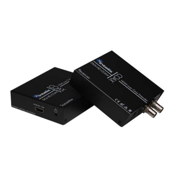
DIGI‐HD‐COAX Installation Manual
Simplify
installations
extenders. The first of its kind, the Intelix DIGI‐HD‐COAX
transmits high‐definition HDMI signals over a single coaxial
cable.
Designed for demanding commercial and residential audio‐
visual applications, the DIGI‐HD‐COAX employs Intelix's
industry‐leading HDMI processing to ensure audio and
video perform flawlessly up to 675 feet using RG6 or RG59.
Plus, built‐in 1x2 distribution amplifiers split video signals
to two independent outputs, thereby allowing dual
distribution systems and/or daisy‐chaining.
Both the transmitter and receiver include two BNC to F
adaptors, ensuring compatibility with different cable
terminations.
Finally, HDMI meets install.
1080p
RG6*
300'
RG59*
250'
*75 ohm cabling
Caution: Do not attempt to disassemble or alter the
extender housing. There are no user-serviceable parts
inside the unit. Doing so will void your warranty.
with
Intelix
DIGI‐HD‐COAX
1080i
675'
675'
1. Power off the source and destination devices
which will be connected to the extenders.
2. Verify the outlets and cross connects to which
you will connect the DIGI‐HD‐COAX are
configured properly and labeled appropriately
to identify the circuit.
Caution:
equipment damage from electrostatic discharge
(ESD), all source and destination equipment must
be powered off during installation.
3. Connect the transmitter (DIGI‐HD‐COAX‐S) to
the HDMI port of the source device.
4. Connect one end of the coaxial cable to the
transmitter via Coax Out A. If necessary,
attach the BNC‐to‐F adaptor to change the
connector type.
5. Connect the receiver (DIGI‐HD‐COAX‐R) to the
HDMI port on the destination device.
6. Connect the other end of the coaxial cable to
the receiver. If necessary, attach the BNC‐to‐F
adaptor to change the connector type.
7. If necessary, connect additional receivers and
destination equipment via Coax Out B on the
transmitter and/or Loop Out on the receiver.
Note: The DIGI-HD-COAX system stores and
distributes the EDID information from the first
connected
720p
displays and/or additional resolutions, the system
must be power cycled.
675'
8. Connect the 5V power supply to the
675'
transmitter.
9. Connect the 5V power supply to the
receiver(s).
10. Power on the destination equipment.
11. Power on the source equipment.
2222 Pleasant View Road
Suite #1
Middleton, WI 53562
Instructions
To
minimize
the
possibility
display.
When
adding
Phone: 608-831-0880
Toll-Free: 866-4-MATMIX
Fax: 608-831-1833
of
additional
Advertisement

Related Manuals for Intelix DIGI?HD?COAX


Summary of Contents for Intelix DIGI?HD?COAX
- Page 1 Simplify installations with Intelix DIGI‐HD‐COAX extenders. The first of its kind, the Intelix DIGI‐HD‐COAX 3. Connect the transmitter (DIGI‐HD‐COAX‐S) to transmits high‐definition HDMI signals over a single coaxial the HDMI port of the source device. cable. 4. Connect one end of the coaxial cable to the ...
-
Page 2: Troubleshooting
6. The maximum operational distances over which Compliancy HDMI 1.3, HDCP 1.1 the DIGI‐HD‐COAX can be transmitted is Shipping Weight 2.1 lbs. dependent on the equipment and cabling. Ensure Intelix Part Numbers Transmit: DIGI-HD-COAX-S that the maximum recommended operational Receive: DIGI-HD-COAX-R distances have not been exceeded. Warranty 2 years 7. Replace the DIGI‐HD‐COAX with another DIGI‐HD‐...
Need help?
Do you have a question about the DIGI?HD?COAX and is the answer not in the manual?
Questions and answers