Bematech MP-4000 TH Service Manual
Pos printer
Hide thumbs
Also See for MP-4000 TH:
- User manual (36 pages) ,
- Quick start manual (48 pages) ,
- Quick start manual (76 pages)
Table of Contents
Advertisement
Quick Links
Advertisement
Table of Contents
Troubleshooting

Related Manuals for Bematech MP-4000 TH


Summary of Contents for Bematech MP-4000 TH
- Page 1 Produto – Rev.1.1...
- Page 2 Bematech S.A. was negligent regarding the design or manufacture of the product. Bematech S.A. shall not be liable against any damages or problems arising from the use of any options or any consumable products other than those designated as original Bematech products or approved products by Bematech S.A.
-
Page 3: Table Of Contents
Summary Introduction......................5 Who should read this manual? .................. 5 How this manual is organized ................... 5 Other related publications and software ..............5 Where to find more information ................5 Chapter 1 ..................... 6 Product Description ....................6 Package contents....................6 Chart of Models ...................... - Page 4 Chapter 2 ................... 26 Procedures ......................26 Product disassembly and assembly procedures for module replacement......26 Precautions before Disassembly and Assembly ............26 Removing the Control Board Set ................26 Removing the Cutter Mechanism, Print Head and Connection Board ......28 Removing the Cover Lever Set ................
-
Page 5: Introduction
Introduction This manual provides information on the identification and troubleshooting, test procedures and a list of replacement parts for the MP-4000 TH printer. Who should read this manual? This manual is intended only for technicians trained by Bematech. How this manual is organized Chapter 1 Knowing the product. -
Page 6: Chapter 1
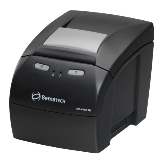
Bematech MP-4000 TH the ideal printing solution for your retail outlet, operating with high quality, high speed and reliability with reduced operation cost. Package contents Remove the MP-4000 TH printer from the package and make sure that all components listed below are available, and that they are in perfect shape: MP-4000 TH Printer;... -
Page 7: Chart Of Models
Chart of Models The MP-4000 TH Printer is available in the following configurations: Model Features 101.2211.10 Black color with Serial communication board (DB-9) 101.2211.11 Black color with Serial communication board (DB-25) 101.2211.12 Black color with Parallel communication board 101.2211.13 Black color with USB communication board 101.2211.15... -
Page 8: Connectors
Cash drawer connector A-1009 CONNECTOR Power Supply connector Cash drawer configuration Position: 1-2 and 5-6 – Epson Standard Drawer 90° 2x4 pin bar Position: 3-4 and 7-8 – Bematech Standard Drawer JST B2B-PH-KS ON/OFF switch connector CONNECTOR PHEC40R-R211LF 40 PIN... -
Page 9: Blocks Diagram
Blocks Diagram STEP MOTOR MOTOR SENSOR SENSORS CUTTER DRIVER IC MECHANISM DRIVER IC THERMAL HEAD RESET DRAWER DRIVER IC D0-D15 SRAM (DATA MEMORY) A1-A19 AT91M55800A COMMUNICATION INTERFACE D0-D15 (ETHERNET, USB, FLASH SERIAL, PARALEL, (FIRMWARE) WI-FI) A1-A19 KEY PANEL BUZZER LEDS... -
Page 10: Parallel Interface Board
Parallel Interface Board The IC U2, ATMEGA16 (microcontroller), is responsible for the communication between the printer and the computer. The IC U3, 74LVC/LCX125 is a buffer and also functions as a level adapter, making the voltage conversion in some signals (5V to 3.3V). The recognition of the interface connected to the control board is done with the reading of a code associated to each kind of board through U1, enabled by the SELDEV signal generated by the control board. -
Page 11: Female Centronics Connector (Printer)
Female Centronics Connector (Printer) Signal nStrobe Data 0 Data 1 Data 2 Data 3 Data 4 Data 5 Data 6 Data 7 nAck Busy Paper-Out/Paper End Select nAuto-Linefeed nInitialize nError / nFault nSelect-Printer nSelect-In 19-30 Ground Communication Cable Male Male Centronics 36 DB-25 19, 20... -
Page 12: Serial Interface Board Db-9
Serial Interface Board DB-9 IC U2 (MAX3232) converts the levels originated into the microcontroller serial interface, which are of 3.3V to signals of ±10V, compatible with RS232 standard and the RS232 signals originated from the outside in 3.3V signals compatible with the microcontroller. The available signals on the interface are RXD, TXD, RTS and CTS. -
Page 13: Block Diagram
Block Diagram MICROTERMINAL / HOST INTERFACE IDENTIFIER FEMALE DB-9 MAX3232 CONNECTOR CONTROL BOARD CONNECTOR (40 PINS) SERIAL COMMUNICATION CONFIGURATION Female DB-9 Connector (Printer) Signal 5 4 3 2 1 9 8 7 6 Communication Cable Male Female DB-9 DB-9 CN A CN B... -
Page 14: Serial Board Db-25
Serial Board DB-25 The ICs U2 and U3 (MAX3232) convert the levels originated from the microcontroller serial interface, which are of 3,3V into signals of ±10V, compatible with RS232 standard and the RS232 signals originated from the outside in 3,3V signals compatible with the microcontroller. The available signs on the interface are RXD, TXD, RTS, CTS, DTR and DSR. -
Page 15: Block Diagram
Block Diagram INTERFACE MICROTERMINAL / IDENTIFIER HOST MAX3232 FEMALE DB-25 CONNECTOR CONTROL BOARD CONNECTOR (40 PINS) MAX3232 SERIAL COMMUNICATION CONFIGURATION Female DB-25 Connector (Printer) Signal 13 12 11 10 9 8 7 6 5 4 3 2 1 25 24 23 22 21 20 19 18 17 16 15 14 INIT Communication Cable CN A... -
Page 16: Usb Interface Board
USB Interface Board The IC U1, CP2102, is the IC responsible for the conversion of CMOS RS-232 signals originated from the control board microcontroller for compatible signals with the USB interface, as well as the conversion of USB signals originated from the outside into CMOS RS-232 signals. The recognition of the interface connected to the control board is done with the reading of a code associated to each kind of board through U2, enabled by the SELDEV signal generated by the control board. -
Page 17: Ethernet Interface Board
Ethernet Interface Board The IC U4, 89C51 (microcontroller), performs the serial communication with the control board and organizes these signals so they are compatible with the TCP/IP protocol and relay data to IC U6 (W3100), which provides the TCP/IP stacks. The integrated circuit U3 (RTL8201B) performs the functions of the Ethernet 10/100Mbps communication standard with the physical device. -
Page 18: Female Rj-45 Connector (Printer)
Female RJ-45 Connector (Printer) Signal Communication Cable Male Male RJ-45 RJ-45 AC Adapter Basic Features • Universal Input Voltage 90 to 264VAC • Power Saving < 0.75W (no load standby) • Consumption: 60W • Output Voltage: 24V • Output Current: 2.5A (typical) •... - Page 19 Connector • Connector type: 3 pins Connector Specification 24VDC Certifications Approved Standards: UL60950, EN60950, UL6500, EN60065.
-
Page 20: Product Exploded View (With Part Numbers)
Product exploded view (with part numbers) ATTENTION! The following part numbers are not necessarily available as stand alone units, as they are part of a replacement kit. For further information, refer to the Support section of our website www.bematech.com Product exploded view... -
Page 21: Exploded View Of The Control Board Cartridge Set
Exploded view of the Control Board Cartridge Set ATTENTION! The following part numbers are not necessarily available as stand alone units, as they are part of a replacement kit. For further information, refer to the Support section of our website www.bematech.com... -
Page 22: Exploded View Of The Cabinet Set
Exploded view of the Cabinet Set ATTENTION! The following part numbers are not necessarily available as stand alone units, as they are part of a replacement kit. For further information, refer to the Support section of our website www.bematech.com... -
Page 23: Exploded View Of The Cover Lever Set
The following part numbers are not necessarily available as stand alone units, as they are part of a replacement kit. For further information, refer to the Support section of our website www.bematech.com Exploded view of the Thermal Print Head Set... -
Page 24: Exploded View Of The Connection Board Set
Exploded view of the Connection Board Set ATTENTION! The following part numbers are not necessarily available as stand alone units, as they are part of a replacement kit. For further information, refer to the Support section of our website www.bematech.com... -
Page 25: Exploded View Of The Cutter Mechanism Set
Exploded view of the Cutter Mechanism Set ATTENTION! The following part numbers are not necessarily available as stand alone units, as they are part of a replacement kit. For further information, refer to the Support section of our website www.bematech.com... -
Page 26: Chapter 2
1. Try to avoid disassembly, assembly and unnecessary adjustments on the MP-4000 TH parts that are working properly; 2. Before turning on the MP-4000 TH, make sure that all cables are properly connected; 3. During the maintenance procedure, do not let loose screws and other components inside the printer;... - Page 27 To remove the control board set, simply pull the cartridge back and then out. When pulling it back, the control board is disconnected from the connection board, located on the frontal portion of the printer. After this, just pull it out of the printer cabinet and you will have the complete control board set on your hands.
-
Page 28: Removing The Cutter Mechanism, Print Head And Connection Board
Removing the Cutter Mechanism, Print Head and Connection Board To access the printer interior, the cutter mechanism, thermal print head connection board, follow the steps below: Begin disassembly by removing the control board cartridge, according to the previous topic. With the printer open, paper roll and spacer removed, loosen the two screws on the inside of the Printer, as shown on the right. - Page 29 The Cutter Mechanism and Connection Board will be removed from the MP-4000 TH base. On the back side of the mechanism, there is a tab that keeps it attached to the base, as...
- Page 30 To separate the connection board from the cutter mechanism, start by loosening the screw that holds the grounding cable located on the side of the equipment, then move away the connection board and disconnect the cables. Below you can see the cutter mechanism, the print head and the connection board with the thermal print head connection cable.
- Page 31 The next steps are required in order to remove the thermal print head. Start by removing the sensors and then the cover lock set. To remove the cutter sensor (located at the front of the mechanism) pull it to the front while opening the locks that hold the mechanism (picture below, on the left).
- Page 32 To remove the paper guide, just press it by its base, disconnecting it from the metal chassis (as shown on the picture on the right). To remove the paper feed motor remove the elastic ring that secures the gears, then pull the gears out.
- Page 33 After disconnecting the plastic chassis, just pull up the back side to loosen the frontal part. Only by separating the two chassis it is possible to have access to the thermal print head. When the chassis assemble is performed, leave the gears and its pins on the same position, both with the pins pointing out (pictures below).
-
Page 34: Removing The Cover Lever Set
Removing the Cover Lever Set To remove the lever set it is recommended that the printer cover is also removed. To remove the printer cover just pull the axle that holds the body case to one side (as shown in the picture on the right). To remove the opening Lever Set, just press it from top to bottom on the points indicated on the picture. -
Page 35: Firmware Update
Firmware update ATTENTION! The product firmware update will only be possible through the serial DB9/DB25 or Ethernet interfaces. The product firmware update can be performed by using the 'User's Software' or the 'Technical Support Software'. User's Software On the tab 'Configuration' select the communication interface (serial DB9/DB25 or Ethernet) and click on apply. -
Page 36: Technical Support Software
Technical Support Software. On the tab 'Configuration' select the communication interface (serial DB9/DB25 or Ethernet) and click on apply. Click on the 'Load' button, on the 'Update firmware' field. On the window that was open select the firmware that will be loaded and click on open. Click on the button 'Update' and wait for the operation end. -
Page 37: Product Test Procedures
Product test procedures Technical Support Software This is the technical support software of the product MP-400 TH; with this software you will be able to test all your printer functions. Tab 'Configuration' At software initialization it will be necessary to configure it before use; this must be the first screen to be accessed before other tabs are used to test the printer functions. -
Page 38: Tab 'Print
1. The text written within this area will be printed after clicking on the button 'Print'. 2. When selected the option 'Formatted text', the fields 'Print type' and 'Format types', will be enabled, use the text format styles to test your MP-4000 TH printer and get to know the print modes it can perform. -
Page 39: Tab 'Bitmap & Logo
1. In this field it is possible to choose an image to be printed in the MP-4000 TH. The option Bitmap allows you to check the graphics printing and the Logo option allows you to test the functions of logo storage and logo printing from volatile and non volatile memories. -
Page 40: Tab 'Bar Code
1. Choose the kind of bar code and type on the field 'Code' the value to be printed by the MP-4000 TH. 2. On this field it is possible to make some changes in the bar code that will be printed. You... -
Page 41: Tab 'Status
Tab 'Status' 1. Click on the button 'Activate' to see the printer status. 2. Click on the button 'Get log' to get a complete report on the printer configuration. -
Page 42: Tab 'Additional Commands
Tab 'Additional Commands' 1. Test the printer buzzer. You can change the time the buzzer will be on and the time it will be off. You can also select how many times you want it to be activated by typing the quantity on the field 'Beeps'. -
Page 43: Tab 'Macro
Tab 'Macro' The tab 'Macro' allows tests to be processed in batch mode. 1. Configure the tests to be performed. The dialogue box 'Text print' allows selecting the formatting and origin of the text (file or keyboard) and how many times the print will be repeated. -
Page 44: Tab 'Tests
Open cover sensor: the cover is closed if the sensor value is over 110. 3. MP-4000 TH printer test phases. Click on the button 'Start' to make a complete test of the printer. Execute the steps as required on the screen. By the end you will have performed a full... -
Page 45: Preventive Maintenance Procedures
Clean the area near the cutter periodically. Use a soft bristle brush removing all paper dust residues which can accumulate in the cutter mechanism, causing malfunction. Sensors Clean the MP-4000 TH sensors using a soft bristle brush. Remove all the dirt accumulated on the lens. Inner Case Make sure the printer is off, open the cover and remove the paper roll. -
Page 46: Chapter 3
Chapter 3 Operation and Troubleshooting Indicative Lights The MP-4000 TH printer will flash indicative messages through the Information LED ( ). The information may vary from the printer ready status to critical error warnings, which can lead to module replacement to correct a specific issue. - Page 47 There is a sensor on the right side of the printer (picture above) that notifies it when the cover is closed. If the error message persists, even if the cover is closed, you can verify the following items: - Is the cover sensor in the indicated location? Is the sensor placed properly? Notice the correct way to insert the sensor on the...
- Page 48 - Verify if the mechanism plastic chassis pins where the sensor is connected (image on the side) are not broken, which would let the sensor out of its position, leading to its malfunction. correct problem, replacement of the plastic chassis will be required.
-
Page 49: Yellow Led Blinking 1 Time - No Paper
Yellow LED blinking 1 time - No Paper. - Is the paper sensor located on the indicated place? Verify if the connection board sensor is properly placed and if there is any dirt obstructing it. - Verify the connection of the board sensor. The correct position to connect this cable is on the CN4 connector (as shown on the image on the side). -
Page 50: Yellow Led Blinking 3 Times - Cutter Error
Yellow LED blinking 3 times - Cutter Error Verify if there is paper between the cutter and the mechanism plastic chassis. If there is and it's not possible to remove it with available tools, cutter disassembly will be necessary. Paper dust congestion, generated by the cutter itself can also cause malfunction. -
Page 51: Red Led Blinking 3 Times - Ram Memory Error
Red LED blinking 3 times - RAM Memory Error RAM memory error on the control board. Replace the control board to address the issue. Red LED blinking 8 times - Print Mechanism Error On the print initialization, the status of the print head and the paper feed motor (picture below) are verified. -
Page 52: Troubleshooting
ASCII. Wrong command sequence Verify if the printer command set is properly configured. It can be configured as Bematech or ESC/POS™. The communication cable may Verify the cable in all its length to be sure that it be damaged or not properly has no indication of physical damage. -
Page 53: Chapter 4
- less time to replace the paper roll and, therefore, more time available for processing transactions at the retail outlet. The MP-4000 TH works with paper rolls of up to 102 mm of diameter and also has an easy and fast paper roll change system (drop in / easy load);... - Page 54 Available Power Supply, Communication Cable, Thermal paper roll. Accessories (1) Please contact Bematech to consult the availability of the interfaces and accessories. (2) It works only with Serial and Ethernet communication interfaces. (3) It doesn't work with USB communication interface.
Need help?
Do you have a question about the MP-4000 TH and is the answer not in the manual?
Questions and answers