Table of Contents
Advertisement
Quick Links
Download this manual
See also:
User Manual
Advertisement
Table of Contents

Related Manuals for Commell LV-67A


Summary of Contents for Commell LV-67A
- Page 1 LV-67A Mini-ITX motherboard User’s Manual Edition: 1.2 2009/06/11...
- Page 2 LV-67A User’s Manual Copyright Copyright 2009. All rights reserved. This document is copyrighted and all rights are reserved. The information in this document is subject to change without prior notice to make improvements to the products. This document contains proprietary information and protected by copyright. No part of this document may be reproduced, copied, or translated in any form or any means without prior written permission of the manufacturer.
-
Page 3: Packing List
LV-67A User’s Manual Packing List Please check package component before you use our products. Hardware: LV-67A Mini-ITX motherboard x 1 Cable Kit: SATA Cable x 2 26-pin Slim Type Floppy Cable x 1 VGA Cable x 1 USB Cable x 1... - Page 4 LV-67A User’s Manual Index Chapter1 <Introduction> ............7 1.1 <Product Overview> .....................7 1.2 <Product Specification> ..................8 1.3 <Block Diagram> ....................10 1.4 <Mechanical Drawing > ..................11 Chapter 2 <Hardware Setup> ..........12 2.1 <Connector Location>..................12 2.2 <Jumper Reference> ..................13 2.3 <Connector Reference>..................14 ..............14...
-
Page 5: Contact Information
LV-67A User’s Manual Chapter 3 <System Configuration> ........38 3.1 <SATA configuration>..................38 3.2 <SATA RAID Configuration> ................39 3.3 <Audio Configuration> ..................43 3.4 <Video Memory Setup> ..................44 3.5 <Display Properties Setting>................46 Chapter 4 <BIOS Setup> ............48 Appendix A <I/O Port Pin Assignment>... - Page 6 LV-67A User’s Manual (This Page is Left for Blank...
-
Page 7: Chapter1
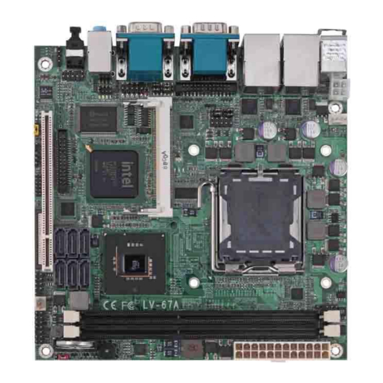
Chapter1 <Introduction> 1.1 <Product Overview> LV-67A is the motherboard with last Intel desktop technology with Mini-ITX form factor. Based on Intel® Q45 and ICH10DO, the board integrates a new Core 2 Quad / Core 2 Duo Celeron processor 775-pin socket, DDR3 memory socket, Intel® Graphic Media Accelerator 4500 technology, Serial ATA II with RAID function for a powerful desktop system. -
Page 8: Product Specification
LV-67A User’s Manual 1.2 <Product Specification> General Specification Form Factor Mini-ITX motherboard Intel® Core 2 Quad / Core 2 Duo / Celeron processor With LGA775 socket Package type: PLGA 775 Front side bus: 800/1066/1333MHZ (200/266/333MHz x 4) Memory 2 x 240-pin DDR3 800/1066MHz SDRAM up to 4GB... - Page 9 LV-67A User’s Manual Ethernet Interface Controller Two Intel 82574L Gigabit Ethernet controller Type Triple speed 10/100/1000Base-T Auto-switching Fast Ethernet Full duplex, IEEE802.3U compliant Connector Two External RJ45 connectors with LED on rear I/O panel Audio Interface Chipset Intel® ICH10DO with Realtek ALC888HD Audio...
- Page 10 LV-67A User’s Manual 1.3 <Block Diagram> Intel Core 2 Quad / Core Due with 775 Pin PLGA CRT1 CH7318 2 x 240-pin DDR3 LVDS CH7308 Intel Q965 800/1066MHz up to 4GB CRT2 CH7317 8 x USB2.0 ports 6 x Serial ATAII ports...
-
Page 11: Mechanical Drawing
LV-67A User’s Manual 1.4 <Mechanical Drawing > Unit: inch... -
Page 12: Chapter 2
LV-67A User’s Manual Chapter 2 <Hardware Setup> 2.1 <Connector Location> DDRIIIA/B JFRNT CN_SMBUS SYSFAN CN_USB S_ATA1~6 CN_DIO CN_IR CN_USB4 CN_DVI1 CPUFAN Mini-PCI CN_12V CN_AUDIO CDIN CN_COM4 CN_DVI1 JCSEL1 JP1/JP2 JCSEL2 Audio COM2+COM3 SPDIF USB_RJ45_1/2 COM1 + CRT... -
Page 13: Jumper Reference
LV-67A User’s Manual 2.2 <Jumper Reference> Jumper Function JRTC CMOS Operating/Clear Setting JVLCD Panel Voltage Setting (LV-67AX) COM1 signal mode switch (For Pin-1 & Pin-9) COM2 signal mode switch (For Pin-1 & Pin-9) Power mode select CN_COM2 RS-232 RS422 RS485 Setting... - Page 14 LV-67A User’s Manual 2.3 <Connector Reference> 2.3.1 <Internal Connectors> Connector Function Remark LGA775 CPU socket DDRIII1/2 240 –pin DDR2 SDRAM DIMM socket 26-pin slim type floppy connector S_ATAII1/2/3/4/5/6 7-pin Serial ATA II connector 24-pin power supply connector CN_12V 4-pin +12V additional power supply connector...
-
Page 15: Cpu And Memory Setup
LV-67A User’s Manual 2.4 <CPU and Memory Setup> 2.4.1 <CPU installation> LV-67A has a LGA775 CPU socket onboard; please check following steps to install the processor properly. Attention If LV-67A need RMA please Keep CPU socket cover on the CPU Socket. -
Page 16: Memory Installation
LV-67A User’s Manual 2.4.2 <Memory installation> LV-67A has two 240-pin DDR3 DIMM support up to 4GB of memory capacity. The memory frequency supports 800/1066 MHz. Only Non-ECC memory is supported. DDRIII A/B 96-pin 144-pin Please check the pin number to match the socket side well... -
Page 17: Cmos Setup
LV-67A User’s Manual 2.5 <CMOS Setup> The board’s data of CMOS can be setting in BIOS. If the board refuses to boot due to inappropriate CMOS settings, here is how to proceed to clear (reset) the CMOS to its default values. -
Page 18: Serial Ata Installation
LV-67A User’s Manual 2.6 <Serial ATA installation> LV-67A has four Serial ATA II interfaces with RAID function, the transfer rate of the Serial ATA II can be up to 300MB/s. Please go to http://www.serialata.org/ for more about Serial ATA technology information. Based on Intel® ICH10DO, it supports Intel® Matrix Storage Technology with combination of RAID 0,1,5 and 10. - Page 19 LV-67A User’s Manual 2.7 <Floppy Installation> LV-67A has one slim type 26-pin floppy interface, it supports notebook use floppy and powering from onboard, please follow up the steps below to install the device. Floppy rear side Lift up this plastic bar...
- Page 20 LV-67A User’s Manual 2.8 <LAN installation> The board integrates with two Intel 82574L Gigabit Ethernet controllers, as the PCI Express bus. The Intel 82574L supports triple speed of 10/100/1000Base-T, with IEEE802.3 compliance and Wake-On-LAN supported. LAN2 LAN1...
- Page 21 LV-67A User’s Manual 2.9 <Onboard Display Interface> Based on Intel Q45 chipset with built-in graphics, the board provides one DB15 Connector on real external I/O port, or optional Secondary CRT connector (LV-67AT) and One 40-pin LVDS interface with 5-pin LCD backlight inverter connector.
- Page 22 LV-67A User’s Manual 2.9.2 <LVDS Display LV-67AX Only > The board provides one 40-pin LVDS connector for 18/24-bit dual channel panels, supports up to 1600 x 1200 (UXGA) of resolution, with one LCD backlight inverter connector and one jumper for panel voltage setting.
- Page 23 LV-67A User’s Manual Connector: CN_INV Connector: JVLCD Type: 5-pin LVDS Power Header Type: 6-pin Power select Header Description Description LCDVCC (3.3V) +12V LCDVCC (5V) LCDVCC (12V) Default setting: 1-2 ENABKL Connector: CN_LVDS Type: onboard 40-pin connector for LVDS connector Connector model: HIROSE DF13-40DP-1.25V...
- Page 24 LV-67A User’s Manual To setup the LCD, you need the component below: A panel with LVDS interfaces. An inverter for panel’s backlight power. A LCD cable and an inverter cable. For the cables, please follow the pin assignment of the connector to make a cable, because every panel has its own pin assignment, so we do not provide a standard cable;...
- Page 25 LV-67A User’s Manual 2.9.3 <DVI Display LV-67AD and LV-67AD2> The board provides optional DVI1-D (LV-67AD) and two DVI (LV-67AD2) interfaces with Intel Q45, compliant with DVI 1.0 standard. Connector: CN_DVI1, CN_DVI2 Connector type: 26-pin header connector (pitch = 2.00mm) Pin Number...
-
Page 26: Audio Installation
LV-67A User’s Manual 2.10 <Audio Installation> The board integrates onboard audio interface with REALTEK ALC888 codec, with Intel next generation of audio standard as High Definition Audio, it offers more vivid sound and other advantages than former HD audio compliance. - Page 27 LV-67A User’s Manual Connector: CN_AUDIO Type: 10-pin (2 x 5) header (pitch = 2.54mm) Description Description MIC_L Ground MIC_R ACZ_DET Speaker_R MIC Detect SENSE Speaker_L Speaker Detect Connector: CDIN Type: 4-pin header (pitch = 2.54mm) Description CD – Left Ground Ground CD –...
- Page 28 LV-67A User’s Manual 2.11 <GPIO and SMBUS interface> The board provides a programmable 8-bit digital I/O interface, and a SMBUS (System management bus) interface for control panel application. Connector: CN_DIO Type: onboard 2 x 6-pin header, pitch=2.0mm Description Description Ground...
-
Page 29: Usb Installation
LV-67A User’s Manual 2.12 <USB Installation> LV-67A integrates eight USB2.0 ports. The specifications of USB2.0 are listed below: Interface USB2.0 Controller Intel ICH10DO Transfer Rate Up to 480Mb/s Voltage The Intel® ICH10DO contains two Enhanced Host Controller Interface (EHCI) and five Universal Host Controller Interfaces (UHCI), it can determine whether your connected device is for USB1.1 or USB2.0, and change the transfer rate automatically. - Page 30 LV-67A User’s Manual Connector: CN_USB Type: 10-pin (5 x 2) header for USB5/6 Ports Description Description Data0- Data1- Data0+ Data1+ Ground Ground Ground CN_USB1 CN_USB4...
-
Page 31: Power And Fan Installation
LV-67A User’s Manual 2.13 <Power and Fan Installation> The LV-67A provides a standard ATX power supply with 24-pin ATX connector and additional 12V connector, and the board provides one 4-pin fan connectors supporting smart fan for CPU cooler and one 3-pin cooler fan connectors for system and Northbridge chip. - Page 32 LV-67A User’s Manual Connector: ATX Type: 24-pin ATX power connector PIN assignment 3.3V 3.3V 3.3V -12V PS_ON PW_OK 5V_SB 3.3V Connector: CN_12V Type: 4-pin standard Pentium 4 additional +12V power connector Description Description Ground Ground +12V +12V Connector: CPUFAN Type: 4-pin fan wafer connector...
- Page 33 LV-67A User’s Manual 2.14 <Serial Port> The board supports Three RS232 serial port and one jumper selectable RS232/422/485 serial ports. The jumper JCSEL1 & JCSEL2 can let you configure the communicating modes for COM2. COM1 COM2 COM3 Connector: COM2 Type: 9-pin D-sub male connector on bracket for COM2...
- Page 34 LV-67A User’s Manual Setting RS-232 & RS-422 & RS-485 for COM2C JP1 JP2 JCSEL1 CN_COM4 JCSEL2...
- Page 35 LV-67A User’s Manual Function JCSEL1 JCSEL2 RS-422 RS-485 RS-232 Default setting: JCSEL1: (1-2) JCSEL2: (1-3, 2-4, 7-9, 8-10) Jumper: JP1/JP2 (COM1/2) Type: onboard 6-pin header Power Mode JP1/JP2 Pin 1 with 5V Power 1-3,4-6 Pin 9 with 12V Power 2-4,3-5...
-
Page 36: Switch And Indicator
LV-67A User’s Manual 2.15 <Switch and Indicator> The JFRNT provides front control panel of the board, such as power button, reset and beeper, etc. Please check well before you connecting the cables on the chassis. Connector: JFRNT Type: onboard 14-pin (2 x 7) 2.54-pitch header... - Page 37 LV-67A User’s Manual (This Page is Left for Blank)
-
Page 38: Chapter 3
LV-67A User’s Manual Chapter 3 <System Configuration> 3.1 <SATA configuration> SATA Mode: This option can let you select whether the Serial ATA hard drives would work under normal IDE mode or RAID mode. The RAID mode need more than one HDD is applied. -
Page 39: Sata Raid Configuration
LV-67A User’s Manual 3.2 <SATA RAID Configuration> The board integrates Intel® ICH10DO with RAID function for Serial ATA II drives, and supports the configurations below: RAID 0 (Stripping): Two hard drives operating as one drive for optimized data R/W performance. It needs two unused drives to build this operation. - Page 40 LV-67A User’s Manual Please press <CTRL+I> to enter the RAID configuration menu. You can setup the RAID under operation system for Microsoft® Windows XP SP1 or Windows 2000 SP4 version, please install the Intel® Application Accelerator Ver.4.5 later to support RAID configuration with Intel® Matrix Storage Technology.
- Page 41 LV-67A User’s Manual 1. After installing Intel Application Accelerator, please execute Intel® Storage Utility. Demo configuration for 2 SATA Drives and set as Intel Matrix Storage Technology set 2. Select Actions to Create RAID Volume Rename the Volume name Select RAID Level as 0...
- Page 42 LV-67A User’s Manual 3. Please select two hard drives to prepare to set the RAID volume 4. Specify the Volume size Tune this bar to specify the volume size, if you specify the volume size lower than maximum, you can create a second volume for another RAID set.
- Page 43 LV-67A User’s Manual 3.3 <Audio Configuration> The board integrates Intel® ICH10DO with REALTEK® ALC888 codec. It can support 2-channel sound under system configuration. Please follow the steps below to setup your sound system. Install REALTEK HD Audio driver. Lunch the control panel and Sound Effect Manager.
-
Page 44: Video Memory Setup
LV-67A User’s Manual 3.4 <Video Memory Setup> Based on Intel® Q45 chipset with GMA (Graphic Media Accelerator) 4500, the board supports Intel® DVMT (Dynamic Video Memory Technology) 3.0, which would allow the video memory be triggered up to 384MB. To support DVMT, you need to install the Intel GMA4500 Driver with supported OS. - Page 45 LV-67A User’s Manual Total GFX Memory Size: This item can let you select a static amount of page-locked graphics memory; which will be allocated during driver initialization. Once you select the memory amount, it will be no longer available for system memory.
-
Page 46: Display Properties Setting
LV-67A User’s Manual 3.5 <Display Properties Setting> Based on Intel Q45 GMCH with GMA3000 (Graphic Media Accelerator), the board supports two DACs for display device as different resolution and color bit. Please install the Intel Graphic Driver before you starting setup display devices. - Page 47 LV-67A User’s Manual Click Monitor to setup the CRT monitor for Colors, Resolution and Refresh Rate Click Intel® Dual Display Clone setup dual display mode as same screen Set the main display device here Click Extended Desktop setup the dual display mode...
-
Page 48: Chapter 4
LV-67A User’s Manual Chapter 4 <BIOS Setup> The motherboard uses the Award BIOS for the system configuration. The Award BIOS in the single board computer is a customized version of the industrial standard BIOS for IBM PC AT-compatible computers. It supports Intel x86 and compatible CPU architecture based processors and computers. - Page 49 LV-67A User’s Manual (This Page is Left for Blank)
-
Page 50: Appendix A
LV-67A User’s Manual Appendix A <I/O Port Pin Assignment> A.1 <Serial ATA Port> Connector: S_ATA1/2/3/4/5/6 Type: 7-pin wafer connector GND RSATA_TXP1 RSATA_TXN1 GND RSATA_RXN1 RSATA_RXP1 GND A.2<Floppy Port> Connector: FDD Type: 26-pin connector Description Description INDEX DRV0 DSKCHG DRV1 MTR1... -
Page 51: A.3
LV-67A User’s Manual A.3 <IrDA Port> Connector: CN_IR Type: 5-pin header for SIR Ports Description IRRX Ground IRTX A.4 <Serial Port> Connector: COM1/2/3 Type: 9-pin D-sub male connector on bracket Description Description Ground Connector: COM4 Type: 9-pin header connector for COM4... -
Page 52: A.5
LV-67A User’s Manual A.5 <VGA Port> Connector: CRT1 Type: 15-pin D-sub female connector on bracket Description Description Description Ground GREEN Ground DDC_DA BLUE Ground HSYNC VSYNC Ground Ground DDC_CLK A.6 <LAN Port> Connector: RJ451/2 Type: RJ45 connector with LED on bracket... -
Page 53: Appedix B
LV-67A User’s Manual Appedix B <System Resources> B.1 <I/O Port Address Map>... - Page 54 LV-67A User’s Manual...
-
Page 55: B.2
LV-67A User’s Manual B.2 <Memory Address Map>... -
Page 56: B.3
LV-67A User’s Manual B.3 <System IRQ Resources>... -
Page 57: Appedix C
LV-67A User’s Manual Appedix C <Flash BIOS> C.1 <BIOS Auto Flash Tool> The board is based on Award BIOS and can be updated easily by the BIOS auto flash tool. You can download the tool online at the address below: h ttp://www.award.com... -
Page 58: Appendix D
LV-67A User’s Manual Appendix D <Programming GPIO’s> The GPIO’can be programmed with the MSDOS debug program using simple IN/OUT commands.The following lines show an example how to do this. GPIO0…..GPIO7 bit0……bit7 -o 2E 87 ;enter configuration -o 2E 87 -o 2E 07 -o 2F 09 ;enale GPIO function... -
Page 59: Appendix E
LV-67A User’s Manual Appendix E <Watch Dog timer Setting > The watchdog timer makes the system auto-reset while it stops to work for a period. The integrated watchdog timer can be setup as system reset mode by program. Timeout Value Range... - Page 60 Taiwan Commate Computer Inc. Address 19F, No. 94, Sec. 1, Shin Tai Wu Rd., Shi Chih Taipei Hsien, Taiwan +886-2-26963909 +886-2-26963911 Website h ttp://www.commell.com.tw E-Mail i nfo@commell.com.tw (General Information) t ech@commell.com.tw (Technical Support) Commell is a brand name of Taiwan commate computer Inc.
Need help?
Do you have a question about the LV-67A and is the answer not in the manual?
Questions and answers