Table of Contents
Advertisement
Quick Links
WARNING: If the information in these
instructions is not followed exactly, a fire or
explosion may result causing property
damage, personal injury or death.
FOR YOUR SAFETY: Do not store or use
gasoline or other flammable vapors and
liquids in the vicinity of this or any other
appliance.
Installation
and
performed by a qualified installer, service
agency or the gas supplier.
THE INSTALLATION MUST BE IN ACCORDANCE WITH LOCAL CODES OR, IN
THE ABSENCE OF LOCAL CODES, WITH THE CURRENT NATIONAL FUEL GAS
CODE ANSI Z233.1 (USA) OR THE CURRENT CAN/CGA B149.1-M86
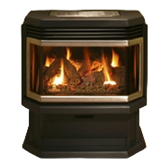
WESTBAY 38
FREESTANDING STOVE
OWNER`S MANUAL
service
must
INSTALLATION CODES (CANADA).
WHAT TO DO IF YOU SMELL GAS:
• Do not try to light any appliance.
• Do not touch any electric switch; do not
use any phone in your building.
• Immediately call your gas supplier
from a neighbor's phone. Follow the
gas supplier's instructions.
be
• If
you
cannot
supplier, call the fire department.
reach
your
gas
45124A
Advertisement
Table of Contents

Subscribe to Our Youtube Channel
Related Manuals for Osburn WESTBAY 38


Summary of Contents for Osburn WESTBAY 38
- Page 1 WESTBAY 38 FREESTANDING STOVE OWNER`S MANUAL WHAT TO DO IF YOU SMELL GAS: WARNING: If the information in these instructions is not followed exactly, a fire or • Do not try to light any appliance. explosion may result causing property damage, personal injury or death.
-
Page 2: Table Of Contents
TABLE OF CONTENTS 1.0 INTRODUCTION ........................... 3 ........................3 PECIFICATIONS ..........................5 EATURES ........................5 NTENDED .........................5 ENERAL AFETY OPERATION ............................6 ......................6 PERATION AFETY ......................7 IGHTING NSTRUCTIONS ....................9 UTPUT DJUSTMENT INSTALLATION ..........................9 & S ..................9 NSTALLATION AFETY OTES ...........................9 NPACKING ........................9 NSTALLATION 3.3.1 ....................10... -
Page 3: Introduction
1.0 INTRODUCTION 1.1 Specifications ITEM NATURAL GAS (NG) PROPANE (LPG) INPUT: Hi 38,000 Btu/hr (11.13 kW) 38,000 Btu/hr (11.13 kW) INPUT: Lo 19,000 Btu/hr (5.57 kW) 27,000 Btu/hr (7.91kW) MANIFOLD PRESSURE: Hi 3.5” w.c. (0.87kPa) 10.5” w.c. (2.62kPa) MANIFOLD PRESSURE: Lo 0.9”... - Page 4 APPLIANCE DIMENSIONS Figure 1 INSTALLATION CODES Installation must conform to local codes. In the absence of local codes, installation must conform to the National Fuel Gas Code, ANSI Z233.1 1988, (in the U.S.), or with the current installation code CAN/CGA B149.1 – M86 (in Canada). The heater, when installed, must be electrically grounded in accordance with ANSI/NFPA No.
-
Page 5: Features
1.3 Intended Use This appliance is intended to be used as a free standing heater. In Massachusetts the Westbay 38 may be installed in a bedroom only when used as a direct vent unit (sealed combustion), no b-vent installation in bedroom or bathroom is allowed. -
Page 6: Operation
2.0 OPERATION 2.1 Operation Safety Inspect the appliance before use. Always keep the appliance area clear and free from combustible materials, gasoline, and other flammable vapors and liquids. Never obstruct the flow of ventilation air. Keep the front of the appliance clear of all obstacles and foreign materials. Never obstruct or modify the air inlet/outlet grilles of the fireplace in any manner. -
Page 7: Lighting Instructions
2.2 Lighting Instructions FOR YOUR SAFETY, READ BEFORE LIGHTING WARNING: If you do not follow these instructions exactly, a fire or explosion may result causing property damage, personal injury or loss of life. A. This appliance is provided with a standing pilot flame. When lighting the pilot, follow these instructions exactly. - Page 8 Igniter Figure 3 Wait a minimum of five minutes to clear out any residual gas. If you then smell gas, STOP! Follow “B” in the Lighting Instruction section described on the previous page. If you don’t smell gas, go to the next step. Press in the gas control knob and turn counter-clockwise to the “PILOT”...
-
Page 9: Heat Output Adjustment
Read all instructions before starting installation and follow them carefully during installation to ensure maximum benefit and safety. Failure to follow these instructions will void your warranty and may present a fire hazard. See the Osburn warranty at the back of this manual for disclaimers regarding improper installation. -
Page 10: Minimum Clearances
3.3.1 Minimum Clearances Minimum Clearances to Combustibles are: A. Alcove width: 54-1/2“(1384mm) D. Side panel to Sidewall: 13-1/2“ (343mm) B. Ceiling Height: 50“(1270 mm) E. Alcove Depth: 26“ (660mm) C. Top of unit to ceiling: 20-1/2“ (521mm) F: Back of unit to back wall: 4“ (102mm) Floor: 0”... -
Page 11: Gas Line Installation
Millivolt thermostats are available from any authorized Osburn dealer. Bedroom installations require the use of a wall thermostat. NOTE: The thermostat or wall switch MUST be rated for millivolt use. Minimize splicing in all millivolt wiring &... - Page 12 TABLE 2: THERMOSTAT WIRE INFORMATION WIRE SIZE MAX. WIRE LENGTH 12.2 19.5 30.5 2. Solder an appropriate wire connector to each wire. To connect to the burner switch, 1/4" female quick connects are required and to connect directly to the valve use spade tongue connectors. 3.
-
Page 13: Direct Vent Information
Figure 6 3.3.4 Direct Vent Information The stove must be connected to Simpson Duravent model 4” x 6 5/8” DV-GS vent, Security Chimneys International (Secure Vent) or Selkirk (Direct-Temp). Install the vent components according to the manufacturer's instructions. Use a maximum of two 90 degree elbows or four 45 degree elbows. - Page 14 The maximum vertical (top vent) system consists of: Up to 30' (9145 mm) of vertical height Fire stop Flashing Collar Low profile termination cap 0980 A rear vent system consists of: “No elbow is allowed in this set-up” Up to a maximum of 24” (610mm) of horizontal length Decorative wall thimble cover Wall Thimble 36”...
- Page 15 Typical Chimney Installation: Vent terminals shall not be recessed into a wall or siding. VENT SNORKEL Figure 7...
-
Page 16: Top / Rear Vent Configuration
3.3.4.1 Top / rear vent configuration Figure 8 Steps required to change the vent configuration on your Westbay 38 Remove the trivet from the top of unit. Remove stove top by removing 2 screws from the rear and one screw from each side (behind cabinet sides) Remove Heat Shield by removing 6 screws. -
Page 17: Use Of Sealant
Use Mil-Pac Black sealant (or equivalent), available from local suppliers or Osburn dealers, on the inner pipe joint, applying the sealant around the outside of the male part of the vent. A bead of silicone should be used on the outside of the joint after assembly to seal the supply air. - Page 18 WARNING: A minimum clearance to combustibles must be maintained around the vent pipe of 2” on horizontal pipe runs and 1” on vertical pipe runs. This model is certified for a maximum horizontal run of 10’ and maximum vertical height of 30’. NOTE: The shaded areas on the vent diagrams indicate where vent restrictor’(s) are to be used.
- Page 19 Mark a 10” x 10” square around the center mark (inside dimensions). Cut and frame the exterior wall to except the Wall Thimble (Duravent part #942 penetration heat shield). Install the Wall Thimble shield using wood screws. If the wall being penetrated is constructed of non-combustible material a 7” hole sufficient for the vent pipe is acceptable.
- Page 20 3.3.4.4VENT TERMINAL LOCATIONS Figure 14 12’’ Clearance above grade, veranda, porch, deck or balcony 12’’ Clearance to window or door that may be opened 12’’ Clearance to permanently closed window 18’’ Vertical clearance to ventilated soffit located above the terminal within a horizontal distance of 2 feet (60 cm) from the center-line of terminal (direct or corner installation) 24’’...
-
Page 21: Optional B-Vent Installation
3.3.5 OPTIONAL B-VENT INSTALLATION This unit may be modified for use as a vented room heater, by using the optional West Bay 38 B-Vent adapter. Follow instructions included with the adaptor when using this option. 3.3.6 FIREBOX COMPONENT INSTALLATION Installing Logs Proper log placement is very important. - Page 22 Installing Logs (continued) Figure 16 Place the first twig across the top of the back log locating it by resting it in the impressions on the back log. The “Y” portion of the first twig is facing down towards the ember bed. (Figure 16) Figure 17 Place the second twig on the left hand side of the logs locating it by resting it in the impressions on the first back twig and the front log.
-
Page 23: Installing The Door
Then remove the hex head screws which are holding the glass retainers in place, remove the remaining broken pieces and clear away any remaining gasket pieces. Replace defective parts with Osburn parts only. Warning: Do not operate the appliance with the glass front removed, cracked or broken. -
Page 24: Manifold Pressure Regulator Adjustment
Occasionally, after a cold start, vapor may condense and fog the glass, and the flames may be partially blue. After a few minutes the moisture will disappear and the flames will become yellow. Visually check the maximum flame height after warm-up (see Figure 19). Figure 19 3.3.8.1Manifold Pressure Regulator Adjustment The manifold pressure regulator controls gas input and flame height and is pre-adjusted at the... -
Page 25: Primary Air Adjustment
3.3.8.3Primary Air Adjustment Figure 21 For most installations no primary air adjustment will be needed, however in a very few instances performance may be improved by sliding the adjustment lever (see above figure). To gain access to the primary air adjustment lever, open front pedestal door and remove the control panel cover. Sliding the lever to the right increases aeration which will cause the flame to appear more transparent and blue making the ceramic fuel effects glow more. -
Page 26: Maintenance
4.0 MAINTENANCE 4.1 Maintenance Safety Turn off the gas to the main burner and allow the heater to cool for up to 30 minutes before servicing. Service and repair should be done by a qualified service person. The appliance should be inspected before use and at least annually by a professional service technician. -
Page 27: Cleaning Of Gold Plated Surfaces
4.4 Cleaning Of Gold Plated Surfaces Take special care and DO NOT use chemical or abrasive cleaners. Wipe only with a soft damp cotton cloth to maintain original brilliance. CAUTION: Vigorous wiping may damage the gold finish. 4.5 Burner & Pilot Cleaning Periodic cleaning is necessary for proper operation. -
Page 28: Trouble Shooting
5.0 TROUBLE SHOOTING SYMPTOM POSSIBLE CAUSE CORRECTIVE ACTION I. Pilot will not light after A. No spark at electrode (weak or no heat source for pilot ignition) repeated triggering of the piezo ignition 1. Poor connections at starter 1. Reconnect if loose button and ignition electrode 2. -
Page 29: Limited Warranty
Gold plating (tarnishing) 5 years Shall your unit or a components be defective, contact immediately your Osburn dealer. Prior to your call make sure you have the following information necessary to your warranty claim treatment: Your name, address and telephone number;...
Need help?
Do you have a question about the WESTBAY 38 and is the answer not in the manual?
Questions and answers