Table of Contents
Advertisement
Quick Links
MCDA-208/WC106
Ultra-Low-Jitter Studio Master Clock with
Dual 1x4 AES/EBU Distribution Amplifier
and 1x6 Clock Distribution Amplifier
OPERATING AND MAINTENANCE MANUAL
© Copyright 2011, DaySequerra Corp.
Day Sequerra │ 154 Cooper Rd. #902 │ W. Berlin, NJ 08091 │ Voice 856-719-9900 │ sales@daysequerra.com │ www.atiaudio.com
Advertisement
Table of Contents

Related Manuals for ATI Audio MCDA-208/WC106


Summary of Contents for ATI Audio MCDA-208/WC106
- Page 1 MCDA-208/WC106 Ultra-Low-Jitter Studio Master Clock with Dual 1x4 AES/EBU Distribution Amplifier and 1x6 Clock Distribution Amplifier OPERATING AND MAINTENANCE MANUAL © Copyright 2011, DaySequerra Corp. Day Sequerra │ 154 Cooper Rd. #902 │ W. Berlin, NJ 08091 │ Voice 856-719-9900 │ sales@daysequerra.com │ www.atiaudio.com...
-
Page 2: Table Of Contents
10 Installation 11 Specifications 12 Warranty 13 MCDA-208/WC106 FEATURES Switchable for use as Master Clock source or 1X6 Clock DA Accepts AES3, S/PDIF, AES11, and Word Clock inputs Independent Dual 1X4 AES/EBU Distribution Amplifiers Generates standard sample rates of 44.1, 48, 88.2, 96, 176.4 or 192 kHz ... -
Page 3: Safety Information
FCC CFR 47, Part 15. CE Declaration of Conformity ATI Audio Inc., West Berlin, New Jersey 08091 USA, declares that all Model MCDA-208/WC106 units are in conformity with the following EU regulations and amendments: Low Voltage Directive (LVD) 2006/95/EC (replaces 73/23/EEC) Electromagnetic Compatibility (EMC): EMC Directive 2004/108/EC EMC: EN55103-1/-2:2009, electromagnetic environments E2. -
Page 4: Air Temperature & Humidity
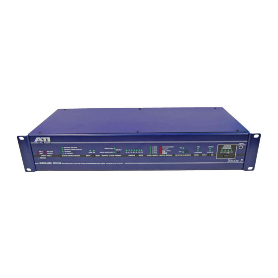
AES3-2003, AES11-2003 and IEC958 SPDIF DESCRIPTION The ATI Model MCDA-208/WC106 is an integrated package containing an ultra-low jitter studio master clock generator, two 1X4 AES/EBU Digital Audio Distribution Amplifiers and one 1X6 Clock Distribution Amplifier. Operation of the unit is simple and straightforward, and it is housed in a rugged 2U rack mount enclosure. -
Page 5: Inputs
When fed from an external reference signal, the MCDA will indicate the clock frequency of the input signal from 32 through 192 kHz. The full diagnostics front panel will also indicate Word Length, Digital Errors if any, and whether the digital stream is Pro or Consumer mode. These diagnostic indicators are switchable to display these details for either AES/EBU input, or for the AES External Sync In or Word Clock input. -
Page 6: Front Panel Display & Switches
FRONT PANEL DISPLAYS AND SWITCHES POWER Indicates that the MCDA is powered and power switch is on. INPUT FAULT Indicates loss of carrier on any of the four inputs, INPUT 1 (AES 1), INPUT 2 (AES 2), AES SYNC-IN (AES SYNC) or WORD CLOCK INPUT (WCLK). -
Page 7: Rear Panel Connections & Switches
INPUT RE-CLOCKING Indicates Input Re-Clocking is On or Off. Press the RE-CLOCKING button to toggle the setting. Note that this function applies only to the AES/EBU inputs and does not affect the AES External Sync and Word Clock inputs. Settings are individual for either INPUT 1 (AES 1) or INPUT 2 (AES 2). , and are memorized and retained through power outages. -
Page 8: Configuration Dip Switches
The switches are labeled left to right BANK A switch “1” is “DIP Switch 1 in the following tables. DIP Switches 7 through 12 have no function in the MCDA-208/WC106. In this view Outputs 1-4 are connected to input 1. OUTPUT 5 to 8 are connected to Word Clock generated by the WORD CLOCK INPUT. - Page 9 SOURCE SELECTION FOR AES/EBU OUTPUTS 1, 2, 3 & 4 EXT AES WORD AES 1 Selected AES/EBU AES/EBU SYNC CLOCK FRAME Source → INPUT 1 INPUT 2 INPUT INPUT CLOCK Down Down Switch 1 Down Down Down Down Switch 2 Down Down Switch 3...
-
Page 10: Block Diagram
MCDA-204 WC106 BLOCK DIAGRAM Input processing includes transformer isolation, cable termination, cable equalization, and AES digital audio interface receiver (DIR) and digital audio interface transmission (DIT). The output of each input signal processor is routed to a multiplexing chip which allows connection to each of the three output groups. -
Page 11: Installation
INSTALLATION LOCATION The MCDA is readily installed into a 2 RU, 19” rack. The MCDA is only to be installed in an inside location where it is protected from inclement weather. Operate the MCDA in temperature range of +5 to +40°C (105°F), with relative humidity ranging from 5 to 85%. -
Page 12: Specifications
MCDA-208/WC106 SPECIFICATIONS INPUTS XLR female for AES/EBU and AES External Sync BNC for Word CONNECTORS Clock LEVEL XLR 200mVp-p minimum; BNC 1 Vp-p Transformer isolated, balanced and floating, XLR 110Ω, BNC 75 Ω; IMPEDANCE input terminations may be switched in or out via front panel control... -
Page 13: Warranty
One Year Limited Warranty DaySequerra warrants ATI products to be free from defects in materials and workmanship to its original owner for one (1) year from the date of purchase. DaySequerra will repair or replace such product or part thereof that upon inspection by DaySequerra, is found to be defective in materials or workmanship subject to conditions contained herein.
Need help?
Do you have a question about the MCDA-208/WC106 and is the answer not in the manual?
Questions and answers