Advertisement
Quick Links
Advertisement

Related Manuals for ATI Audio AT5XXNC


Summary of Contents for ATI Audio AT5XXNC
- Page 1 AT5XX CLASS D 2 TO 8-CHANNEL POWER AMPLIFIER OWNER’S GUIDE...
- Page 2 PRECAUTIONS The AT5XX amplifier is a wide-band design with substantial power output capability. Certain precau- AT5XX tions must be taken to ensure proper operation. Never expose the amplifier to moisture. • Never plug an input cable into the amplifier while the unit is turned on. •...
- Page 3 SAFETY INSTRUCTIONS Read all the safety and operating instructions before connection or using the AT5XX All warnings on the unit and in this operating manual should be adhered to. • All operating instructions should be followed. • Do not place/use the unit near water; for example, near a bathtub, washbowl/sink, •...
- Page 4 Amplifier Identification Record This information is for your records and for future identification of the AT5XX . Please take a moment to fill out all pertinent data now, and as upgrades and/or options are installed. Whenever upgrades, inquiries and/or changes are requested, the serial number will be required. MODEL NUMBER SERIAL NUMBER DATE PURCHASED...
- Page 5 PREFACE CONGRATULATIONS. You have just acquired one of the most advanced audio components available. Your AT5XX amplifier was designed to provide a state-of-the-art listening experience and is suitable for use with associated components of the highest order. The amplifier uses N-Core NC-500 class D amplifier modules with ATI designed custom gain stage and linear power supply to deliver superior performance.
-
Page 6: Table Of Contents
SAFETY WARNING .......................... i SAFETY INSTRUCTIONS ......................ii AT5XX Identification Record ...................... iii Preface……………………………………………………………………………….…………..iv Table of Contents ..........................1 INTRODUCTION ..........................1 Getting to know your amplifier....................... 1 Burn-In/Break-In Time ........................1 Reference Manual Conventions ......................1 IMPORTANT NOTICE ........................1 Front Panel Layout ........................... -
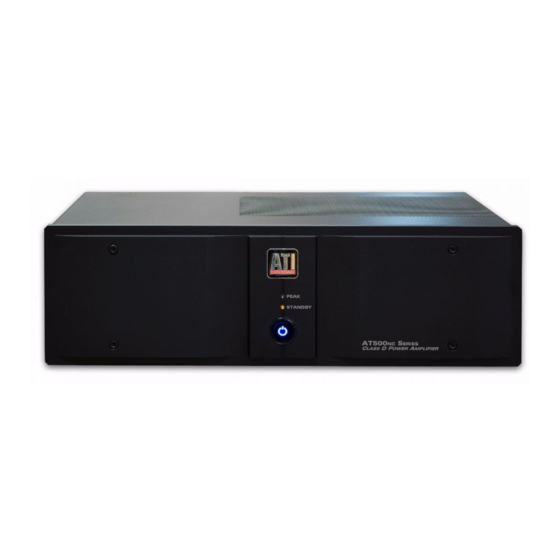
Page 7: Front Panel Layout
Front Panel Layout 1 2 3 4 1. LOGO. 2. PEAK POWER LED. Illuminates whenever any channel r eaches full output. 3. STANDBY LED. When the MAIN POWER switch is pr essed, the STANDBY LED illuminates until the amplifier has completed the turn-on process and enters the playback mode. -
Page 8: Rear Panel Layout
Rear Panel Layout A B C D E F G H I Rear Panel Layout A. Balanced XLR Audio Inputs Use the BALANCED INPUT jacks to connect to the outputs of a preamplifier or other control device with XLR outputs. B. -
Page 9: Operation
Connect the amplifier’s output to the input of the speaker that is in- tended to be driven. Connect a 12V trigger source to the STANDBY trigger input of the AT5XXNC using the supplied cable or a cable with a 3.5 mm monophonic plug to enable remote turn-on and turn-off. -
Page 10: Appendix A Troubleshooting Guide
Appendix A Troubleshooting Guide If the amplifier should function abnormally during operation, please review the items in the following checklist. Please be sure to thoroughly check all other connected components such as speakers and preamplifiers, as well as cables. If the problem persists, please consult your dealer or distributor. -
Page 11: Appendix B Specifications
Appendix B Specifications Analog Audio Inputs One Single-ended (RCA) jack per channel; One Balanced (XLR) jack per channel Input Impedance 47 kΩ. Balanced for each phase Input Sensitivity 2.82V RMS input for 300W into 8 ohms Gain 27.8 dB Polarity (Single-Ended) Non-Inverting Balanced;... -
Page 12: Warranty
90-Day Limited Warranty Transferability Terms and Conditions The above warranties are transferable to subsequent owners as (7-Year Optional Extended Warranty) long as all of the conditions are met under the Optional Extend- ed Warranty Program. The warranty is not transferable if the This ATI product is warranted against defects in materials and unit was originally purchased from an unauthorized seller.
Need help?
Do you have a question about the AT5XXNC and is the answer not in the manual?
Questions and answers