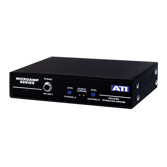
Summary of Contents for ATI Audio DA2008
- Page 1 DA2008 DISTRIBUTION AMPLIFIERS OPERATING AND MAINTENANCE MANUAL © Copyright 2012, DaySequerra Corp. Day Sequerra │ 154 Cooper Rd. #902 │ W. Berlin, NJ 08091 │ Voice 856-719-9900 │ sales@daysequerra.com │ www.atiaudio.com...
- Page 2 DESCRIPTION ICs developed primarily for the instrumentation market had many shortcomings when used in high quality audio applications. The lack of audio related specifications, crossover distortion, high noise for low source impedances, limited output capability and limited gain bandwidth product forced many compromises when used in audio systems.
- Page 3 OUTPUTS Audio from the input buffer is AC coupled to the front panel level adjusts potentiometers. The pot outputs are applied to the non-inverting input of the HI (in-phase) output stage driver ICs. The ICs supply the first 10 ma of output current directly and then complementary Class B output booster transistors take over.
- Page 4 The four inch silver bearing copper strap, which you are, of course, using for your station ground is not going to fit around the #6 chassis ground screw on the DA2008 rear panel. Run the strap to within a few inches of the chassis and jump to the chassis ground with shield braid.
- Page 5 Caution: Balanced differential outputs have active drivers for both HI and LO output terminals. DO NOT GROUND either HI or LO terminals. Two separate 600 ohm unbalanced loads can be driven from each output without interaction by connecting one between HI and GND and the other between LO and GND. The two loads thus driven will be out of phase with each other.
- Page 6 Technical Specifications +24 dBm/600 ohms OUTPUT CLIPPING LEVEL: @ +24 dBm output DISTORTION: 0.2% maximum THD, 20 to 20kHz and input levels to +24 dBm +/-.25 db, 20 to 20000 Hz. –3 db at 100KHz. FREQUENCY RESPONSE: -70-dBm maximum OUTPUT NOISE: 20kHz measurement bandwidth 600-ohm source impedance full gain 80db for common mode hum inputs.


Need help?
Do you have a question about the DA2008 and is the answer not in the manual?
Questions and answers