Table of Contents
Advertisement
Quick Links
Advertisement
Table of Contents

Related Manuals for Crestron HD-SCALER


Summary of Contents for Crestron HD-SCALER
- Page 1 Crestron HD-SCALER High-Definition Video Scaler Operations & Installation Guide...
-
Page 2: Regulatory Compliance
Crestron, the Crestron logo, Cresnet, Crestron Toolbox, QuickMedia, QuickSwitch HD, and SIMPL are trademarks or registered trademarks of Crestron Electronics, Inc. in the United States and other countries. Dolby is a registered trademark of Dolby Laboratories. DTS is a registered trademark of DTS, Inc. -
Page 3: Table Of Contents
Crestron HD-SCALER High-Definition Video Scaler Contents High-Definition Video Scaler: HD-SCALER Introduction ..........................1 Features and Functions ....................1 Applications......................... 4 Specifications ......................5 Physical Description....................10 Setup ............................14 Network Wiring......................14 Identity Code ......................14 Installation ......................... 15 Hardware Hookup ..................... 17 Programming Software...................... -
Page 5: High-Definition Video Scaler: Hd-Scaler
Provides detailed input/output signal information on screen (Continued on following page) 1. The HD-SCALER supports any input or output resolution and scan rate that has a pixel clock of 165 MHz or lower. 2. HDMI IN requires an appropriate adapter or interface cable to accommodate a DVI or DisplayPort multimode signal. - Page 6 Crestron MPS Series products or through an appropriate adapter (not included). Composite and S-video signals are not detected automatically and must be selected programmatically or manually. 4. The HD-SCALER supports any input or output resolution and scan rate that has a pixel clock of 165 MHz or lower.
- Page 7 These include various color bars, line and grid patterns, RGB and grayscale ramps, streak and streak boost, raster, solid colors, and several aspect ratio boxes. Even as a portable device, the HD-SCALER provides an invaluable setup tool.
-
Page 8: Applications
High-Definition Video Scaler Crestron HD-SCALER Applications The diagram below shows an HD-SCALER in a typical application. HD-SCALER in a Typical Application 4 • High-Definition Video Scaler: HD-SCALER Operations & Installation Guide – DOC. 7136A... -
Page 9: Specifications
Crestron HD-SCALER High-Definition Video Scaler Specifications Specifications for the HD-SCALER are listed in the following table. HD-SCALER Specifications SPECIFICATION DETAILS Features Universal HD video scaler and deinterlacer, 3D motion-adaptive filter, 3D noise reduction, MPEG noise reduction, 2:2 and 2:3 pull-down sequence... - Page 10 Component 480i 576i 480p 576p 720p50 720p60 1080i25 (1125 lines) 1080i30 1080p30 1080p50 (1125 lines) 1080p60 480i Composite and S-video 576i (Continued on following page) 6 • High-Definition Video Scaler: HD-SCALER Operations & Installation Guide – DOC. 7136A...
- Page 11 ® HDMI Dolby Digital, Dolby Digital EX, DTS DTS-ES, DTS 96/24, up to 8ch PCM Analog Stereo 2-Channel Analog-to-Digital Conversion 24-bit 48 kHz (Continued on following page) High-Definition Video Scaler: HD-SCALER • 7 Operations & Installation Guide – DOC. 7136A...
- Page 12 Width 7.43 in (189 mm) Depth 1.24 in (32 mm) Weight 1.8 lb (0.79 kg) Included Accessory 24 Volt DC Power Pack, Universal (Continued on following page) 8 • High-Definition Video Scaler: HD-SCALER Operations & Installation Guide – DOC. 7136A...
- Page 13 6. The latest software versions can be obtained from the Crestron Web site. Refer to the NOTE following these footnotes.
-
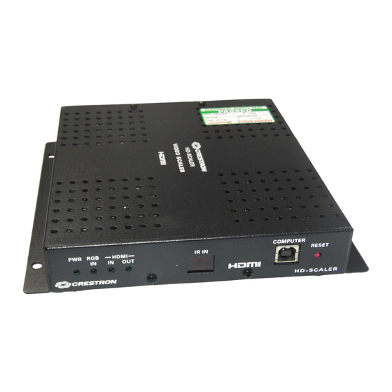
Page 14: Physical Description
High-Definition Video Scaler Crestron HD-SCALER Physical Description This section provides information on the connections, controls and indicators available on your HD-SCALER. HD-SCALER Physical Views (Left and Right Sides Shown) 10 • High-Definition Video Scaler: HD-SCALER Operations & Installation Guide – DOC. 7136A... - Page 15 7.36 in (175 mm) (187 mm) 5.25 in (134 mm) 1.24 in (32 mm) 7.43 in (189 mm) HD-SCALER Connectors, Controls & Indicators (Left and Right Side Views) High-Definition Video Scaler: HD-SCALER • 11 Operations & Installation Guide – DOC. 7136A...
- Page 16 USB 2.0 computer console port Pin 2 Pin 1 (6 foot (~1.8 meters) cable included) DESCRIPTION +5 VDC Pin 3 Pin 4 Data - Data + Ground (Continued on following page) 12 • High-Definition Video Scaler: HD-SCALER Operations & Installation Guide – DOC. 7136A...
- Page 17 2. The RGBHV input can accept component, composite, and S-video signals via direct interface to Crestron MPS Series products or through an appropriate adapter (not included). Composite and S-video signals are not detected automatically and must be selected programmatically or manually.
-
Page 18: Setup
For more details, refer to “Check Network Wiring” on page 29. Identity Code The Net ID of the HD-SCALER has been factory set to A3. The Net IDs of multiple HD-SCALER devices in the same system must be unique. Net IDs are changed from a personal computer (PC) via Crestron Toolbox™... -
Page 19: Installation
HD-SCALER can also be mounted on a rack rail. Mounting on a Flat Surface To mount the HD-SCALER on a flat surface such as a wall or ceiling, use four mounting screws (not included). The following illustration shows mounting of the HD-SCALER on a wall. -
Page 20: Rack Mounting
Crestron HD-SCALER Rack Mounting To mount the HD-SCALER on the front or rear rail of a rack, do the following: 1. Position either mounting flange of the HD-SCALER so that the holes align with the holes in the rack (refer to the illustration below). -
Page 21: Hardware Hookup
NOTE: The supported power supply configuration is either the external power pack (included) or a Cresnet power supply. A Cresnet power supply and the included power pack cannot be connected to the HD-SCALER at the same time. High-Definition Video Scaler: HD-SCALER • 17... -
Page 22: Programming Software
Have a question or comment about Crestron software? Answers to frequently asked questions (FAQs) can be viewed in the Online Help section of the Crestron Web site. To post a question or view questions you have submitted to Crestron’s True Blue Support, log in at www.crestron.com/support. - Page 23 Crestron HD-SCALER High-Definition Video Scaler C2Net Devices, Slot 9 2. If additional HD-SCALER devices are to be added, repeat step 1 for each device. Each HD-SCALER is assigned a different Net ID number as it is added. 3. If necessary, double-click a device to open the “Device Settings” dialog box and change the Net ID as shown in the following illustration.
-
Page 24: Uploading And Upgrading
Crestron Toolbox help file for details. There is one method of communication: USB. USB Communication The COMPUTER port on the HD-SCALER connects to the USB port on the PC via a Type A to Type B USB cable: 1. Use the Address Book in Crestron Toolbox to create an entry using the expected communication protocol (USB). -
Page 25: Ir Remote Operation
The HD-SCALER is shipped from the factory with an IR remote (refer to the illustration below). HD-SCALER IR Remote To operate the remote, point it at the IR IN receiver window on the HD-SCALER and press the appropriate buttons. Refer to the table below for descriptions of the buttons. - Page 26 BUTTON DESCRIPTION EDID Specifies whether the analog/digital input EDID is to be set to DFLT in which the HD-SCALER DFLT/COPY sends a list of default resolutions to the source or set to COPY in which resolutions are read from the display and sent to the source.
-
Page 27: On-Screen Display
HD-SCALER. The main menu of the HD-SCALER OSD is shown below. HD-SCALER OSD Main Menu As shown above, the main menu of the HD-SCALER OSD consists of five items: 1. Analog Input: Accesses the Analog Input submenu, which allows configuration of analog input parameters (refer to “Configuring Analog Input Parameters”... - Page 28 High-Definition Video Scaler Crestron HD-SCALER HD-SCALER OSD Menu Tree 24 • High-Definition Video Scaler: HD-SCALER Operations & Installation Guide – DOC. 7136A...
- Page 29 To navigate to the left (-) or to the right (+) when adjusting a setting in a slider (for example, Brightness): or . • To save a setting in a slider: Press OK. High-Definition Video Scaler: HD-SCALER • 25 Operations & Installation Guide – DOC. 7136A...
-
Page 30: Configuration
High-Definition Video Scaler Crestron HD-SCALER Configuration Configuration of input and output signals is performed from the HD-SCALER OSD using the supplied IR remote. For information about the remote, refer to “IR Remote Operation” on page 21. Configuring Analog Input Parameters To configure analog input parameters, navigate to the Analog Input main menu item and then press OK on the IR remote. -
Page 31: Configuring Digital Input Parameters
EDID of the display or copied (cloned) from the output EDID of the display. • Overscan: Sets overscan to None (default), 2.5%, 5.0%, or 7.5%. In addition, the Signal Information menu item provides display of digital input signal information. High-Definition Video Scaler: HD-SCALER • 27 Operations & Installation Guide – DOC. 7136A... -
Page 32: Configuring Output Parameters
In addition, the Output submenu also allows display of test patterns and provides display of EDID video and audio information as well as video and audio output signal information. 28 • High-Definition Video Scaler: HD-SCALER Operations & Installation Guide – DOC. 7136A... -
Page 33: Problem Solving
Cresnet power usage of the entire chain. If the unit is run from a Crestron system power supply network port, the Cresnet power usage of that unit is the Cresnet power usage of the entire run. -
Page 34: Further Inquiries
Make sure the cable length value is less than the value calculated on the right side of the equation. For example, a Cresnet run using 18 AWG Crestron Certified Wire and drawing 20 watts should not have a length of run more than 333 feet (101 meters). If Cresnet HP is used for the same run, its length could extend to 1250 feet (381 meters). -
Page 35: Return And Warranty Policies
Purchasers should inquire of the dealer regarding the nature and extent of the dealer's warranty, if any. CRESTRON shall not be liable to honor the terms of this warranty if the product has been used in any application other than that for which it was intended or if it has been subjected to misuse, accidental damage, modification or improper installation procedures. - Page 36 Crestron Electronics, Inc. Operations & Installation Guide – DOC. 7136A 15 Volvo Drive Rockleigh, NJ 07647 (2029518) Tel: 888.CRESTRON 04.11 Fax: 201.767.7576 Specifications subject to www.crestron.com change without notice.
Need help?
Do you have a question about the HD-SCALER and is the answer not in the manual?
Questions and answers